
Related Manuals for Axiometrix Solutions imc C Series


Summary of Contents for Axiometrix Solutions imc C Series
- Page 1 imc C-SERIES Manual Edition 10 - 2023-06-06 © 2023 imc Test & Measurement GmbH imc Test & Measurement GmbH • Voltastr. 5 • 13355 Berlin • Germany...
- Page 2 Disclaimer of liability The contents of this documentation have been carefully checked for consistency with the hardware and software systems described. Nevertheless, it is impossible to completely rule out inconsistencies, so that we decline to offer any guarantee of total conformity. We reserve the right to make technical modifications of the systems.
- Page 3 Notes regarding this document This document provides important notes on using the device / the module. Safe working is conditional on compliance with all safety measures and instructions provided. The manual is to be used as a kind of reference book.
-
Page 4: Table Of Contents
Table of contents Table of contents 1 General introduction ....................6 1.1 imc Customer Support / Hotline ....................6 1.2 Legal notices ........................... 6 1.3 Explanation of symbols ........................9 1.4 Last changes in content ........................ 10 2 Safety ........................11 3 Assembly and connection .................. - Page 5 Table of contents 8.6 CS-5008-FD, CL-5016-FD analog inputs ..................148 8.7 CS-7008-FD, CL-7016-FD analog inputs ..................152 8.8 Technical Specs DI / DO / ENC / DAC ..................157 8.9 CAN FD Interface ........................161 8.10 Miscellaneous ........................... 162 9 Pin configuration ....................171 9.1 DSUB-15 pin configuration ......................
-
Page 6: General Introduction
imc Customer Support / Hotline Chapter 1 1 General introduction 1.1 imc Customer Support / Hotline If you have problems or questions, please contact our Customer Support/Hotline: imc Test & Measurement GmbH Hotline (Germany): +49 30 467090-26 E-Mail: hotline@imc-tm.de Internet: https://www.imc-tm.com International partners For our international partners see https://www.imc-tm.com/distributors/. - Page 7 Legal notices Chapter 1 Guarantee Each device is subjected to a 24-hour "burn-in" before leaving imc. This procedure is capable of detecting almost all cases of early failure. This does not, however, guarantee that a component will not fail after longer operation. Therefore, all imc devices are granted liability for a period of two years.
- Page 8 Legal notices Chapter 1 FCC-Notice This product has been tested and found to comply with the limits for a Class B digital device, pursuant to Part 15 of the FCC Rules. These limits are designed to provide reasonable protection against harmful interference in a residential installation.
-
Page 9: Explanation Of Symbols
Explanation of symbols Chapter 1 1.3 Explanation of symbols CE Conformity see CE chapter 1.2 No household waste Please do not dispose of the electrical/electronic device with household waste, but at the appropriate collection points for electrical waste, see also chapter 1.2 Potential compensation Connection for potential compensation... -
Page 10: Last Changes In Content
Explanation of symbols Chapter 1 RoHS of the PR China The limits for hazardous substances in electrical/electronic equipment applicable in the PRC are identical to those in the EU. The restrictions are complied with (see chapter 1.2 ). A corresponding "China-RoHS" label is omitted for formal/economic reasons. Instead, the number in the symbol indicates the number of years in which no hazardous substances are released. -
Page 11: Safety
Chapter 2 2 Safety This section provides an overview of all important aspects of protection of the users for reliable and trouble-free operation. Failure to comply with the instructions and protection notes provided here can result in serious danger. Responsibility of the operator Devices of the imc C-SERIES are for use in commercial applications. - Page 12 Chapter 2 Special hazards This segment states what residual dangers have been identified by the hazard analysis. Observe the safety notes listed here and the warnings appearing in subsequent chapters of this manual in order to reduce health risks and to avoid dangerous situations.
- Page 13 Chapter 2 Observe notes and warnings Devices from imc have been carefully designed, assembled and routinely tested in accordance with the safety regulations specified in the included certificate of conformity and has left imc in perfect operating condition. To maintain this condition and to ensure continued danger-free operation, the user should pay particular attention to the remarks and warnings made in this chapter.
-
Page 14: Assembly And Connection
After unpacking... Chapter 3 3 Assembly and connection 3.1 After unpacking... Check the delivered system immediately upon receiving it for completeness and for possible transport damage. In case of damage visible from outside, proceed as follows: · Do not accept the delivery or only accept it with reservations ·... -
Page 15: Notes On Connecting
Notes on connecting Chapter 3 3.3 Notes on connecting 3.3.1 Precautions for operation Certain ground rules for operating the system, aside from reasonable safety measures, must be observed to prevent danger to the user, third parties, the device itself and the measurement object. These are the use of the system in conformity to its design, and the refraining from altering the system, since possible later users may not be properly informed and may ill-advisedly rely on the precision and safety promised by the manufacturer. - Page 16 Notes on connecting Chapter 3 3.3.2 Power supply Each device is powered by a DC-supply voltage which is supplied via a 2-pin LEMO-plug. Type designation LEMO plug: Device LEMO plug type designation Size FGG.1B.302 CLAD 52ZN middle FGG.0B.302 CLAD 52ZN small The permissible supply voltage range is 10 ...
- Page 17 Notes on connecting Chapter 3 3.3.3 Grounding, shielding In order to comply with Part 15 of the FCC-regulations applicable to devices of Class B, the system must be grounded. 3.3.3.1 Devices with non-isolated power supply CS devices The DC-supply input on the device itself (LEMO-socket) is not galvanically isolated from the housing (CHASSIS): -SUPPLY input is galvanically connected to CHASSIS internally.
- Page 18 Notes on connecting Chapter 3 3.3.3.4 Grounding with power supplied by a car battery imc CL Devices with isolated DC-supply (e.g. battery) If the power supply (e.g. car battery) and the measurement device are at different voltage levels, then if they were connected by the supply line, it would cause a ground loop.
- Page 19 Notes on connecting Chapter 3 3.3.3.5 Shielding Also, all signal leads to the device must be shielded and the shielding grounded (electric contact between the shielding and the plug housing "CHASSIS"). To avoid compensation currents, always connect the shielding to one side (potential) only.If the imc DSUB block screw terminal plug is used, the shielding should be connected to the pull-relief clamp on the cable bushing.
- Page 20 Notes on connecting Chapter 3 3.3.6 Main switch The main switch of all CS-devices takes the form of a flip switch. The main switch of the CL-devices takes the form of a rocker switch, which activates the device when it is tipped for approx.
- Page 21 Notes on connecting Chapter 3 3.3.8 UPS Devices with DC supply input are equipped with an uninterruptible power supply (UPS). This allows for a continuous operation unaffected by temporary short-term outage of the main power supply. This type of operation is particularly useful for operation in a vehicle, permanently attached to starter lock and main power switch and thus not requiring manual control.
- Page 22 Notes on connecting Chapter 3 3.3.8.3 Take-over threshold The voltage threshold at which the storage battery takes over the power supply from the external source is approx. 9.75 V (8.1 V for CS). The take-over procedure is subjected to an hysteresis to prevent oscillating take- over.
- Page 23 Notes on connecting Chapter 3 3.3.10 Removable storage For saving measured data, all imc devices support a removable storage medium. The slot for the CF removable memory is located on the front of the devices, see adjacent figure. Removing the removable memory when the device is switched on If you remove the removable storage without notice, defective clusters may result.
- Page 24 Notes on connecting Chapter 3 3.3.11 Signal connection For devices with DSUB-15 connection technology, the convenient imc terminal plugs for solderless screw terminal connection are available as optional accessories. ACC/DSUBM-xxx: snap the nose into the slot Open the Metal plug: 1.
-
Page 25: Maintenance And Servicing
Maintenance and servicing Chapter 4 4 Maintenance and servicing 4.1 Maintenance and servicing No special maintenance measures are required. Corrective repair work may only be performed at factory by imc Test & Measurement GmbH. There are a number of important device characteristics which should be subjected to precise checking at regular intervals. -
Page 26: Start Of Operation Software / Firmware
Installation - Software Chapter 5 5 Start of operation Software / Firmware 5.1 Installation - Software The associated measurement engineering software imc STUDIO, the configuration and operating interface for all imc instruments, provides the devices with exceedingly versatile functionality. It achieves comprehensive total solutions for everything from laboratory tests through mobile data logger application all the way to complete industrial test stations. -
Page 27: Connecting Via Lan In Three Steps
Connect the device Chapter 5 In very demanding applications, you might consider grouping multiple GBit Ethernet devices via even higher- performance sections lines of the network (e.g. via 5 GBit Ethernet) and to connect these groups to NAS-components, for instance, via these lines. When such imc devices are included which use network-based PTP-synchronization (e.g. CRXT or CRFX-2000GP), then it is necessary to use network switches which fully support this protocol on the hardware side. - Page 28 Connecting via LAN in three steps Chapter 5 Once the dialog starts, the system automatically searches for all devices in the network. In the tree diagram, all available devices are indicated. If the device If there is any IP-conflict, appears among the group "Currently not reachable" ①, it is necessary to modify devices affected will not the device's LAN-settings.
- Page 29 Connecting via LAN in three steps Chapter 5 If there is a direct connection between the device and the PC by a cable, then DHCP should not be used. In order to apply the changes, click on the button "Apply". Wait for the device to restart and then close the dialog.
-
Page 30: Firmware Update
Firmware update Chapter 5 5.4 Firmware update Every software version comes with matching firmware for the hardware. The software only works with devices having the right firmware. Once the program connects up with the unit, the device's firmware is checked. If the software version doesn't match the device's firmware version, you are asked if you want to perform a firmware-update. - Page 31 Firmware update Chapter 5 The following symbols for the individual firmware components appear in the list: Symbols not current firmware conforms to current standards error occurred during update procedure — this option is not available on the device If no status indicators are displayed, no connection could be made to the corresponding device. The duration of the update depends on the amount of amplifiers (can last up to several minutes).
- Page 32 Firmware update Chapter 5 Warning Be sure to observe in case of error · For a variety of reasons, the firmware update sometimes does not conclude properly, for example due to interruption of the power supply. For instance, the "handshake signal" at the end of the procedure may be missing.
-
Page 33: Properties Of The Imc C-Series
Chapter 6 6 Properties of the imc C-SERIES The imc C-SERIES consists of smart network-capable, unventilated compact measurement devices for all-purpose measurement of physical quantities. These devices can operate either in computer-aided or autonomous mode and are lightweight, compact, and robust, thus, especially well adapted to applications in R&D or in the testing of mechanical and electromechanical components of machines, on board vehicles, or in monitoring tasks in installations. -
Page 34: Device Overview
Device overview Chapter 6 6.1 Device overview Some of the capabilities discussed in this document only pertain to certain device models. The associated device groups are indicated at the respective locations. The groups are shown in the following table. — not available ●... -
Page 35: Measurement Types
Measurement types Chapter 6 6.2 Measurement types 6.2.1 Temperature measurement Two methods are available for measuring temperature. Measurement using a PT100 requires a constant current, e.g. of 250 µA to flow through the sensor. The temperature-dependent resistance causes a voltage drop which is correlated to a temperature according to a characteristic curve. - Page 36 Measurement types Chapter 6 6.2.1.2 PT100 (RTD) - measurement RTD (PT100) sensors can be directly connected in 4-wire-configuration. An additional reference current source feeds a chain of up to 4 sensors in series. With the imc Thermo plug, the connection terminals are already wired in such a way that this reference current loop is closed.
- Page 37 Measurement types Chapter 6 6.2.1.3.1 Schematic: T4 plug Plastic plug (ACC/DSUB-T4, discontinued) Metal plug (ACC/DSUBM-T4) 6.2.2 Bridge measurement Bridge channels are for taking readings from measurement bridges such as resistor bridges or strain gauges. The channels are equipped as non-isolated differential amplifiers and can alternatively be used for direct measurement of voltages.
- Page 38 Measurement types Chapter 6 6.2.3 Bridge measurements with wire strain gauges Strain in this sense refers to the ratio of a body's original length to the change in length due to a force exerted upon it. By selecting "Strain gauge" as the measurement mode, common bridge circuits and configurations for wire strain gauges are offered for selection.
- Page 39 Measurement types Chapter 6 6.2.3.1 Quarter bridge for 120 Ohm strain gauge This strain gauge arrangement uses an active strain gauge which is positioned on the test object in a uniaxial stress field. This strain gauge is joined by three passive resistors within the module to form a full bridge. The strain gauge can have a resistance value of 120 Ω.
- Page 40 Measurement types Chapter 6 6.2.3.3 Poisson half bridge In this circuit, two active strain gauges are used. The strain gauge is positioned transverse to the main direction of strain. The transversal contraction is exploited. For this reason, the Poisson's ratio for the material, which is its transversal expansion coefficient, must be supplied along with the gauge factor.
- Page 41 Measurement types Chapter 6 6.2.3.5 Half bridges with one active and one passive strain gauge This circuit involves strain gauges. The first one is positioned on the test object, the second on a sample of the same material under the same ambient temperature and serves the purpose of temperature compensation. The strain is computed as: Legend: gauge factor...
- Page 42 Measurement types Chapter 6 6.2.3.7 Full bridge with Poisson strain gauges in opposed branches Two active strain gauges are positioned along the longitudinal strain and are joined by two transversally positioned strain gauges to complete the bridge (torsion bar arrangement). In the bridge, the longitudinal strain gauges are located in opposite branches.
- Page 43 Measurement types Chapter 6 6.2.3.9 Full bridge with 4 active strain gauges in uniaxial direction The circuit consists of 4 active strain gauges. Two are under compression and the others under equal tension. The strain gauges under tension are positioned in opposite bridge arms. The sensitivity to the moment of bending is increased.
- Page 44 Measurement types Chapter 6 Transverse strain coeff. (poisson's ratio): If a body suffers compression or tension and is able to be freely deformed, then not only its length but also its thickness changes. This phenomenon is known as transversal contraction. It can be shown that for each kind of material, the relative change in length is proportional to the relative change in thickness D.
- Page 45 Measurement types Chapter 6 6.2.4 Incremental Counters Channels The incremental counter channels are for measuring time or frequency-based signals. In contrast to the analog channels as well as to the digital inputs, the channels are not sampled at a selected, fixed rate, but instead time intervals between slopes (transitions) or number of pulses of the digital signal are measured.
- Page 46 Measurement types Chapter 6 6.2.4.1 Signals and conditioning 6.2.4.1.1 Mode The various modes comprise the following measurement types: Event-counting Time Combined measurements · · · events time frequency · · · distance(differential) pulse time speed · · angle (differential) · angle (sum) ·...
- Page 47 Measurement types Chapter 6 Time Measurements Exclusive measurement of time is performed as: · time (of two successive signal edges) · pulse time (time from the beginning of one sampling interval until the next signal edge) Any other pulses occurring within the sampling interval are not evaluated for these measurement types. time pulse time Combination Mode...
- Page 48 Measurement types Chapter 6 The derivative quantities displacement and angle measurement have the following settings: · Choice of single-track and dual-track encoder · Start of measurement with or without "Zero impulse" · Number of pulses (per unit) The input ranges and resolutions for the RPM or velocity also depend on the number of encoder pulses set. If the number of pulses is known, the RPM and velocity values can easily be computed using the above table according Parameter Description...
- Page 49 Measurement types Chapter 6 The table below summarizes the various measurement types' units; the bold/cursive letters denote the (fixed) primary quantity, followed by its (editable) default physical unit: Measurement quantity (Sensor-) scaling Range Maximum Linear motion pulse/m Angle pulse/U U/min Velocity pulse/m pulse/U...
- Page 50 Measurement types Chapter 6 The size of the hysteresis represents the width of a range-band inside of which the signal can fluctuate (due to signal noise and interference) without an impulse being recorded. Ranges: · VREF (Threshold) = -10 V .. +10V ·...
- Page 51 Measurement types Chapter 6 6.2.4.2 Mode (events-counting) Mode - Events Description Events The event counter counts the sensor pulses which occur during a single time interval (differential event counting). The interval corresponds to the sampling time set by the user. The maximum event frequency is about 500 kHz.
- Page 52 Measurement types Chapter 6 6.2.4.3 Mode (time measurement) Time measurement The time measurement mode allows the definition of edge conditions between which the time interval is to be measured. The following combinations are possible: positive edge > negative edge: (↑ > ↓) negative edge >...
- Page 53 Measurement types Chapter 6 Pulse Time The point in time at which the edge is located within the sampling interval is determined. This information is needed by some functions in imc Online FAMOS, e.g. for determining the course of the RPMs from a pulse signal: OtrEncoderPulsesToRpm.
- Page 54 Measurement types Chapter 6 6.2.4.4 Mode (combined measurement) Mode Beschreibung Frequency Frequency is determined by means of a combination measurement . If the frequency was previously multiplied or divided, this can be reflected in the scaling value. The frequency is always unsigned, for which reason there is no dual-track encoder for it.
-
Page 55: Measurement With Current-Fed Sensors (Iepe)
Measurement types Chapter 6 6.3 Measurement with current-fed sensors (IEPE) With current-fed sensors (e.g. ICP™-, DELTATRON®-, PIEZOTRON®-, PIEZOBEAM®-sensors), the capacitive burden on the signal due to the cable capacitance can lead to clipped amplitudes for higher frequencies. To avoid signal distortion, try to: 1. -
Page 56: Measure With Iepe/Icp Expansion Plug
Measurement with current-fed sensors (IEPE) Chapter 6 6.3.1 Supply current The exact magnitude of the supply current is irrelevant for the measurement's precision. Values of 2 mA tend to be adequate. Only in the case of very high bandwidth and amplitude signals in conjunction with very long cables, supply currents may be a concern, as considerable currents are need to dynamically charge the capacitive load of the cable. - Page 57 Measure with IEPE/ICP expansion plug Chapter 6 · Each channel can be switched to DC-coupled voltage measurement or current-fed IEPE/ICP measurement (AC-coupled); ex-factory the DIP-Switch for each channel inside the plug is switched to IEPE/ICP measurement (AC-coupled) · For the supply of this expansion plug, the amplifier used provides a voltage of 5 V. This voltage is short- circuit proof and independent of the voltage supply .
- Page 58 Measure with IEPE/ICP expansion plug Chapter 6 DIP-Switch position ICP (DIP-Switch inside of the expansion plug): · The AC-coupling is already provided by the ICP-plug, the voltage channel is DC-coupled. · The measurement range must be adapted to the signal's AC-component, it can be adjusted within the range: ±5 V to ±250 mV ·...
- Page 59 Measure with IEPE/ICP expansion plug Chapter 6 The following circuit schematic display an entire plug. The DIP switches are not included in order to achieve a more simple schematic. © 2023 imc Test & Measurement GmbH imc C-SERIES - Manual, Edition 10 - 2023-06-06 Page 59...
- Page 60 Measure with IEPE/ICP expansion plug Chapter 6 6.4.3 ACC/DSUBM-ICP2I-BNC(-F,-S) This expansion plug is used to extend imc measurement amplifiers with DSUB-15 sockets with an IEPE conditioning which allows the direct connection of 2 current-fed IEPE/ICP sensors, e.g. IEPE microphones, accelerometers of the type ICP™-DeltaTron®- or PiezoTron® etc. The IEPE conditioning comprises 4 mA current supply and AC coupling and is channel-individually isolated.
- Page 61 Measure with IEPE/ICP expansion plug Chapter 6 Two variants of the expansion plug are available: · The S variant (slow) achieves minimum cutoff frequency, thus limits the lower bandwidth of the sensor as little as possible. However, the transient response after plugging in (activation) can take longer (>10 seconds).
- Page 62 Measure with IEPE/ICP expansion plug Chapter 6 Basic functionality (ICP-operation) does not require software support and has no associated requirements. However, for support of sensor TEDS functionality and for improved offset performance it is required that the plug is recognized and supported by the operation software. In particular this involves the activation of an additional digital high pass filter to remove some small residual offset that results from the high impedance AC coupling.
- Page 63 Measure with IEPE/ICP expansion plug Chapter 6 6.4.3.1 Plug recognition via TEDS function Expansion plug without TEDS Information of the sensor When using the IEPE/ICP-expansion plug without any sensor connected, or in conjunction with a simple passive sensor without any TEDS memory, the software acknowledges this procedure with "apparent" error messages which in reality, however, just reflect the fact that no TEDS data of the actual sensor are recognized.
- Page 64 Measure with IEPE/ICP expansion plug Chapter 6 Expansion plug in conjunction with/without TEDS-capable sensor When a sensor with its own TEDS memory is connected, its read out properties are recognized, such as the scaling and the unit. Only in this case, where there is valid TEDS information about the sensor itself, the input coupling of the channel will be displayed as "AC with current supply".
- Page 65 Measure with IEPE/ICP expansion plug Chapter 6 6.4.3.2 Software recognition The ICP expansion plug supports ICP transducers with integrated TEDS memory (Class I MMI). The plug itself is also recognized via the TEDS functionality. The TEDS mechanism is used for plug recognition even when the actually used transducer that is connected to the plug does not support TEDS and does not incorporate any TEDS memory at all.
- Page 66 Measure with IEPE/ICP expansion plug Chapter 6 Only with CRFX: Alternatively, you can obtain verification with CRONOSflex by pulling out the plug, forcing a "Download" (e.g. toggling the input range and returning it to original setting). This will lead to the following message: 6334 The required imc clamp terminal ACC/DSUB-ICP is not connected! This test only works with CRFX! With CRC and C-SERIES however, it is not possible to do a check in this...
- Page 67 Measure with IEPE/ICP expansion plug Chapter 6 Firmware-Update / behavior upon starting In all device families, as a rule the stand-alone device performs plug recognition upon Power-Up. in order to be able to take into account any plug-specific processes for possible autostart configurations. If this has not been successfully verified, an automatic measurement will not be started and a corresponding error message is stored on the onboard flash (device memory).
- Page 68 Measure with IEPE/ICP expansion plug Chapter 6 6318 The sensor is not connected directly, or is not making sensor information available! Cause: Reading of sensor information (TEDS) was unsuccessful. In conjunction with the ICP expansion plug: Correct recognition of an expansion plug, without connected sensor (BNC open): not an error! In conjunction with "normal"...
- Page 69 Measure with IEPE/ICP expansion plug Chapter 6 © 2023 imc Test & Measurement GmbH imc C-SERIES - Manual, Edition 10 - 2023-06-06 Page 69...
-
Page 70: Device Description
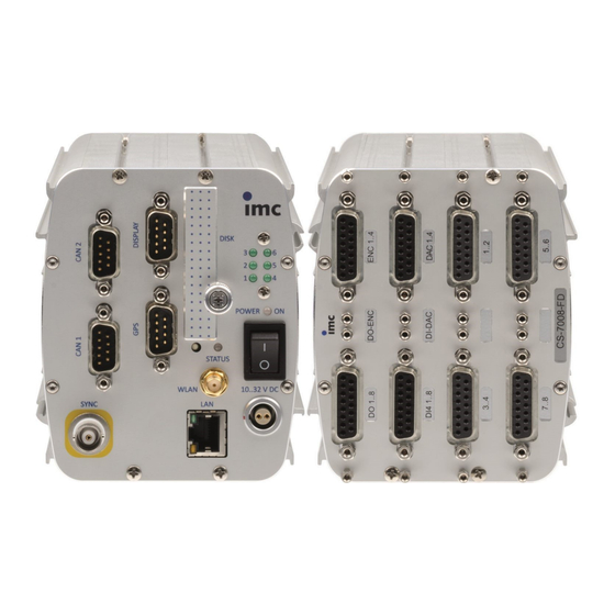
Chapter 7 7 Device description CS-7008-FD CL-7016-FD CL-7016-FD Reference CL devices are equipped ex-factory with an internal display at the front. Alternatively an external display can be connected, but then the internal display will be deactivated ex-factory. © 2023 imc Test & Measurement GmbH imc C-SERIES - Manual, Edition 10 - 2023-06-06 Page 70... -
Page 71: Hardware Configuration Of All Devices
Hardware configuration of all devices Chapter 7 7.1 Hardware configuration of all devices All devices belonging to the imc C-SERIES are equipped with: · · 4 incremental counter inputs 8 digital inputs · · 4 analog outputs 8 digital outputs 7.1.1 Digital In- and Outputs, Inputs for Incremental counters There are 8 binary inputs, 8 binary outputs and 4 incremental counter inputs available. - Page 72 Hardware configuration of all devices Chapter 7 7.1.1.1.2 Sampling interval and brief signal levels The digital inputs can be recorded in the manner of an analog channel. It isn't possible to select individual bits for acquisition; all 16 bits (digital port) are always recorded. The hardware ensures that the brief HIGH level within one sampling interval can be recognized.
- Page 73 Hardware configuration of all devices Chapter 7 Inductive loads (relays, motors) should be equipped with a clamp diode in parallel for shorting out switch-off transients (anode to output, cathode to positive supply voltage). Power-up response: deactivated high-Z (high resistance) power-up high-Z (high resistance) High- and LowSide switch inactive first write access With "Prepare measurement"...
- Page 74 Hardware configuration of all devices Chapter 7 7.1.1.2.2 Possible configurations Open Drain 5 V (internal) Totem Pole Device off: no continuity/high impedance Device off: no continuity/high impedance (138 kΩ), 0 V at output Device booting: no continuity/high impedance Device booting: no continuity/high impedance, (138 kΩ), 0 V at output 0 V at output After booting process:...
- Page 75 Hardware configuration of all devices Chapter 7 7.1.1.3 Incremental counter channels You can find a general description in the chapter of the "Incremental Counters Channels ". Reference technical specification of the incremental counter channels The pin configuration of the ACC/DSUBM-ENC4 7.1.1.3.1 Sensor types, synchronization Index signal denotes the synchronization signal SYNC which is globally available to all four channels in common.
- Page 76 Hardware configuration of all devices Chapter 7 7.1.1.3.2 Comparator conditioning The incremental counter channels' special properties make special demands on the signal quality: The very high time-resolution of the detector or counter means that even extremely short impulses which sampling measurement procedures (as at the digital inputs) would miss are captured and evaluated.
- Page 77 Hardware configuration of all devices Chapter 7 7.1.1.3.3 Structure Complete conditioning with individual differential inputs is provided for 4 tracks: they can be used for four channels with single-track encoders or for two channels with dual-track encoders. Block schematic Dual-track encoders (quadrature encoders) emit two signals offset by 90° of phase, the tracks A and B. By evaluating the phase information between the A and B-track, the direction of turning can be determined.
- Page 78 Hardware configuration of all devices Chapter 7 7.1.1.3.5 Incremental counter track configuration options Mode Channel 1 Channel 2 Channel 3 Channel 4 single-track encoder ● ● ● ● dual-track encoder single-track encoder shows signal value 0 ● ● dual-track encoder ●...
- Page 79 Hardware configuration of all devices Chapter 7 7.1.1.3.7.1 Connection: Open-Collector Sensor Simple rotary encoder sensors are often designed as an Open-Collector stage which outputs a signal which ranges between the states 0 V and SUPPLY. In this case, the switching threshold should be set to half the SUPPLY voltage: sensor with open-collector output 7.1.1.3.7.2 Connection: Sensors with RS422 differential line drivers...
- Page 80 Hardware configuration of all devices Chapter 7 7.1.2 Analog outputs The analog outputs DAC 01 to 04 provide 4 analog output channels to be used as dynamic control and actuator signals. The outputs can be defined as the results of calculations performed by imc Online FAMOS on data from combinations of measurement channels.
- Page 81 Hardware configuration of all devices Chapter 7 7.1.3 Storage Media Alongside transfer to the PC, it is also possible to save measured data on removable data storage media. The operating software allows free selection of data storage options (see the description of data storage in the operating software’s user manual).
- Page 82 Hardware configuration of all devices Chapter 7 Exchanging the data carrier In case you are using a removable storage medium, please be aware that before you remove it (if the device is switched on), the Hotplug button must be pressed to ensure that storage medium can be safely removed. When you click on the Hotplug button, you request the system to remove the removable data carrier.
- Page 83 Hardware configuration of all devices Chapter 7 7.1.4 Fieldbus interfaces 7.1.4.1 CAN, CAN FD If your imc device is equipped with at least 2 nodes (DSUB-9), each of them is supposed to be connected with a Y-adaptor. imc C-SERIES with connected Y-adaptor Note that for a transfer rate of 1 Mbit/s to the CAN-Bus the stub line of a tee-junction may only be up to 30 cm long.
-
Page 84: Miscellaneous
Miscellaneous Chapter 7 7.2 Miscellaneous 7.2.1 Filter settings 7.2.1.1 Theoretical background The filter setting is especially important in a signal-sampling measurement system: the theory of digital signal processing and especially the sampling theorem (Shannon, Nyquist) state that for such a system, the signal must be restricted to a limited frequency band to ensure that the signal has only negligible frequency components beyond one-half of the sampling frequency ("Nyquist-frequency"). - Page 85 Miscellaneous Chapter 7 The automatic selection of the cutoff frequency in the setting "AAF" is based on the following criteria: · In the pass band, a maximum (AC-) gain uncertainty of 0.06% = -0.005 dB is permitted. The pass band is defined by the cutoff frequency at which this value is exceeded.
- Page 86 Miscellaneous Chapter 7 7.2.2 External sensor supply 7.2.2.1 External +5 V supply voltage For a majority of the imc measuring modules there is a 5 V supply voltage available for an external sensors or for the IEPE/ICP expansion plug. This source is not isolated; its reference potential is identical to the overall system's ground reference.
- Page 87 Miscellaneous Chapter 7 mode voltage due to the measurement setup, or if the -SUPPLY return lines are already exposed to uncontrolled ground loops, an isolated sensor supply may be advisable. Note The supply voltage is set on each channel group and does apply to all inputs of this group. For the number of channels per group is depending on the type of device.
- Page 88 Miscellaneous Chapter 7 7.2.4.1 Optical SYNC Adapter: ACC/SYNC-FIBRE One fundamental feature of all imc measurement devices, is their ability to synchronize multiple devices, even of differing models, and to operate them all in concert. The synchronization is typically accomplished by means of a Master/Slave process via the electrical SYNC-signal, which terminates on the devices at a BNC socket.
- Page 89 Miscellaneous Chapter 7 7.2.5 IRIG-B module This external IRIG-B module can convert a time signal in IRIG format to the GPS format NMEA 0183 and thus be used for synchronization of different devices. The expansion module exclusively supports amplitude modulated IRIG signals according to the standards IRIG- B1xx! This is why it can be used both to upgrade older imc device generations which provided no IRIG-B support at all, and to enhance current imc device generations with additional capabilities regarding modulated signals: While many up-to-date imc device series (CRFX, CRC, C-SERIES) offer IRIG-B synchronization via their standard...
- Page 90 Miscellaneous Chapter 7 The IRIG-B module comprises a realtime clock (RTC) with a backup battery, which is set to time and date according to the IRIG B-signal received. If the IRIG B year codes received equal "00" (depending on used sub-standard) these are ignored and only RTC time and day values are set, while the year continues to reflect the value resulting from counting since the last update with a valid year number.
- Page 91 Miscellaneous Chapter 7 GPS information Description pv.GPS.time.sec The number of seconds since 01.01.1970 00:00 hours UTC. For this reason, it is no longer possible to assign the value to a Float-format channel without loss of data. This count of seconds can be transformed to absolute time under Windows and Linux.To do this, use the function below.
- Page 92 Miscellaneous Chapter 7 NMEA-Talker IDs Supported NMEA-Talker IDs: · GA: Galileo Positioning System · GB: BeiDou (BDS) (China) · GI: NavIC (IRNSS) (India) · GL: GLONASS, according to IEIC 61162-1 · GN: Combination of multiple satellite systems (GNSS) (NMEA 1083) ·...
- Page 93 Miscellaneous Chapter 7 7.2.7 WiFi (WLAN) connection Measurement devices can optionally be equipped with a built-in WiFi (WLAN) adapter. An alternative wireless network connection may especially useful in applications such as mobile test drives. Measurement devices can be equipped with WiFi (WLAN) adapters conforming to the standard IEEE 802.11g, which achieve maximum gross transfer rates of 54 Mbit/s.
- Page 94 Miscellaneous Chapter 7 7.2.8 Operation without PC To operate your imc measurement device , you don't necessarily need a PC. Your device will start the measurement independently, if an autostart has been prepared. Using the display, you can use its keyboard to control the measurement.
-
Page 95: Cs-1016-Fd
Miscellaneous Chapter 7 7.3 CS-1016-FD CS-1016 is a 16-channel measurement device, for voltage and current measurement tasks, with sampling rates of up to 20 kHz per channel. Technical details: CS-1016-FD analog inputs The device come with 16 differential, non-isolated input channels which can be used for measuring voltage In addition, current... -
Page 96: Cs-1208-Fd
CS-1016-FD Chapter 7 7.4 CS-1208-FD CS-1208-FD is a 8-channel universal measurement device, respectively, for voltage and current measurement tasks (20 mA), with sampling rates of up to 100 kHz per channel. In particular, the high bandwidth of 48 kHz, the input ranges from 50 V to 5 mV and the low signal noise predestine this device for high-performance voltage measurements. - Page 97 CS-1208-FD Chapter 7 7.4.1.1 Voltage source with ground reference The voltage source itself already is referenced to the device's ground. The voltage source is at the same potential as the device ground. Example The unit is grounded. Thus, the input GND is at ground potential. If the voltage source itself is also grounded, it is referenced to the device ground.
- Page 98 CS-1208-FD Chapter 7 Example A voltage source which isn't grounded (e.g. a battery) and whose contacts have no connection to ground potential is measured. The device is grounded. Note When –IN and GND are connected, be sure that the signal source's potential can actually be drawn to the device ground's potential without an appreciable current flowing.
- Page 99 CS-1208-FD Chapter 7 7.4.2 Current measurement · Current: e.g. ±50 mA to ±1 mA For current measurement, the DSUB plug ACC/DSUBM-I4 must be used. This plug is not included in the standard package. It contains a 50 Ω shunt. In addition, voltage can be measured via an externally connected shunt. The appropriate scaling must be set in the user interface.
-
Page 100: Cs-3008-Fd
CS-1208-FD Chapter 7 7.5 CS-3008-FD The measuring inputs (non-isolated, differential inputs) are used for voltage measurement and allow direct connection of any IEPE type sensors via BNC, such as ICP™, DeltaTron®, accelerometers or microphones, see technical details 7.5.1 Voltage measurement ·... - Page 101 CS-3008-FD Chapter 7 Note · In the coupling mode "AC with current supply" respectively "IEPE", an open-circuit current-fed voltage of about 30 V is present at the BNC sockets, which can cause damage to other (non-current-fed) sensor types. For that reason, this mode should only be set for appropriate sensors. It is assured that no current feed is active when the device is started.
- Page 102 CS-3008-FD Chapter 7 7.5.1.3 Case 2: Voltage source without ground reference The voltage source itself has no reference to the device's ground, but instead, its potential floats freely compared to the device ground. If a ground reference cannot be established, it's also possible to connect the negative signal input –IN to the ground contact GND.
-
Page 103: Cs-4108-Fd, Cl-4124-Fd
CS-3008-FD Chapter 7 7.6 CS-4108-FD, CL-4124-FD CS-4108-FD and CL-4124-FD are 8- and 24-channel universal measurement devices, respectively, with sampling rates of up to 50 kHz per channel. They are specially designed for measurement tasks in environments with unclear voltage fields such as test rigs or large-scale machinery. The input channels are electrically isolated, differential and equipped with per-channel signal conditioning including filters. - Page 104 CS-4108-FD, CL-4124-FD Chapter 7 7.6.2 Temperature measurement The input channels are designed for measurement with thermocouples and PT100-sensors (RTD, platinum resistance thermometers). Any combinations of the two sensor types can be connected.A detailed description of temperature measurement is presented here Temperature measurement is performed with the imc plug ACC/DSUBM-T4 .
- Page 105 CS-4108-FD, CL-4124-FD Chapter 7 instance by grounding one of the four connection cables: the PT100 reference current source is referenced to the device's frame (CHASSIS), and is thus not isolated. 7.6.3 Current fed sensors At the DSUB-15 sockets, a permanent 5 V supply voltage for external sensors is available.
- Page 106 CS-4108-FD, CL-4124-FD Chapter 7 7.6.4 Current measurement · Current: ±40 mA, ±20 mA, ±10 mA ... ±1 mA in 6 ranges A special plug (ACC/DSUBM-I4) with a built-in shunt (50 Ω) is needed for current measurement. For current measurement with the special shunt-plugs ACC/DSUBM-I4, inputs ranging only up to max. ±50 mA (corresponding to 2 V or 2.5 V voltage ranges) are permitted due to the measurement shunt's limited power dissipation in the case of static long-term loading.
- Page 107 CS-4108-FD, CL-4124-FD Chapter 7 7.6.6 Connection For signal connections, DSUB-15 plugs can be used. Reference Please find here the DSUB-15 pin configuration © 2023 imc Test & Measurement GmbH imc C-SERIES - Manual, Edition 10 - 2023-06-06 Page 107...
-
Page 108: Cs-5008-Fd, Cl-5016-Fd
CS-4108-FD, CL-4124-FD Chapter 7 7.7 CS-5008-FD, CL-5016-FD This C-50xx devices provides eight differential, analog inputs with integrated sensor supply for the measurement of resistive bridges or strain gauges, as well as voltage, current and IEPE/ICP-sensors. A software selectable sensor supply is included, for powering of external sensors or resistive bridge / strain gauge networks. - Page 109 CS-5008-FD, CL-5016-FD Chapter 7 7.7.1.1 Full bridge Please note that the maximum allowed voltage drop along a cable may not exceed approx. 0.5 V. This determines the maximum possible cable length. If the cable is so short and its cross section so large that the voltage drop along the supply lead is negligible.
- Page 110 CS-5008-FD, CL-5016-FD Chapter 7 7.7.1.3 Quarter bridge A quarter bridge can consist of a single strain gauge resistor, whose nominal value can be 120 Ω or 350 Ω. The amplifier internally completes an additional 120 Ω or 350 Ω quarter bridge switchable by software. The quarter bridge has 3 terminals to connect.
- Page 111 CS-5008-FD, CL-5016-FD Chapter 7 7.7.1.5 Balancing and shunt calibration The module offers a variety of possibilities to trigger bridge balancing: · Balancing / shunt calibration upon activation (cold start) of the unit. If this option is selected, all the bridge channels are balanced as soon as the device is turned on.
- Page 112 CS-5008-FD, CL-5016-FD Chapter 7 7.7.2 Voltage measurement · Voltage: ±10 V to ±5 mV in 9 different ranges The input impedance is 20MΩ. (1MΩ when switched off) 7.7.2.1 Voltage source with ground reference The voltage source itself already has a connection to the device's ground.
- Page 113 CS-5008-FD, CL-5016-FD Chapter 7 7.7.2.3 Voltage source at a different fixed potential The common mode voltage (U ) has to be less than ±10 V. It is reduced by ½ input voltage. Example: Suppose a voltage source is to be measured which is at a potential of 120 V to ground.
- Page 114 CS-5008-FD, CL-5016-FD Chapter 7 7.7.3 Current measurement The current measurement is realized with shunt plug or with ground reference via the internal quarter bridge completion. 7.7.3.1 Differential current measurement Note Requirement The following statements only apply for modules with DSUB sockets. ·...
- Page 115 CS-5008-FD, CL-5016-FD Chapter 7 7.7.3.2 Ground-referenced current measurement · Current: ±50 mA to ±2 mA In this circuit, the current to be measured flows through the 120 Ω shunt in the amplifier. Note that here, the terminal -VB is simultaneously the device's ground. Thus, the measurement carried out is single-ended or ground referenced.
- Page 116 CS-5008-FD, CL-5016-FD Chapter 7 Note There is a voltage drop across the resistances of the leadwires and the internal measuring resistance of 120 Ω which is proportional to the amperage. This lost voltage is no longer available for the supply of the transducer (2.4 V = 120 Ω · 20 mA).
-
Page 117: Cs-7008-Fd, Cl-7016-Fd
CS-5008-FD, CL-5016-FD Chapter 7 7.8 CS-7008-FD, CL-7016-FD CS-7008-FD and CL-7016-FD are 8- and 16-channel universal measurement devices, respectively, with sampling rates of up to 100 kHz per channel. They are especially well suited to frequently changing measurement tasks. Practically every sensor- or signal type can be connected directly to any of the measurement amplifier's all- purpose channels. - Page 118 CS-7008-FD, CL-7016-FD Chapter 7 7.8.1.1 Voltage source with ground reference The voltage source itself already has a connection to the device's ground. The potential difference between the voltage source and the device ground must be fixed. Example The device is grounded. Thus, the input -VB is also at ground potential. If the voltage source itself is also grounded, it's referenced to the device ground.
- Page 119 CS-7008-FD, CL-7016-FD Chapter 7 7.8.1.3 Voltage source at a different fixed potential The common mode voltage (V ) has to be less than ±10 V. It is reduced by ½ input voltage. Example Suppose a voltage source is to be measured which is at a potential of 120 V to ground.
- Page 120 CS-7008-FD, CL-7016-FD Chapter 7 7.8.2 Bridge measurement Measurement of measurement bridges such as strain gauges. The measurement channels have an adjustable DC voltage source which supplies the measurement bridges. The supply voltage for a group eight inputs is set in common.
- Page 121 CS-7008-FD, CL-7016-FD Chapter 7 If the cable is so short and its cross section so large that the voltage drop along the supply lead is negligible, the bridge can be connected at four terminals by omitting the Sense line. 7.8.2.2 Half bridge A half bridge may consist of two strain gauges in a circuit or a sensor internally configured as a half bridge, or a potentiometer sensor.
- Page 122 CS-7008-FD, CL-7016-FD Chapter 7 7.8.2.4 Sense and initial unbalance The SENSE lead serves to compensate voltage drops due to cable resistance, which would otherwise produce noticeable measurement errors. If there are no sense lines, then SENSE must be connected in the terminal plug according to the sketches above.
- Page 123 CS-7008-FD, CL-7016-FD Chapter 7 7.8.3 Current measurement 7.8.3.1 Differential current measurement For current measurement the DSUB plug ACC/DSUBM-I2 is mandatory. The ACC/DSUBM-I2 comes with a 50 Ω shunt and is not included with the standard package. It is also possible to measure a voltage via an externally connected shunt.
- Page 124 CS-7008-FD, CL-7016-FD Chapter 7 7.8.3.3 2-wire for sensors with a current signal and variable supply · e.g. for pressure transducers 4 mA to 20 mA. Transducers which translate the physical measurement quantity into their own current consumption and which allow variable supply voltages can be configured in a two-wire circuit.
- Page 125 CS-7008-FD, CL-7016-FD Chapter 7 Note · In the imc software user interface, the option isolated thermocouple (default setting) must be activated under Settings - Configuration - Amplifier. This only is available with Coupling DC. Reference Please find here a description of the available thermocouples 7.8.4.1.1 Thermocouple mounted with ground reference The thermocouple is mounted in such a way that it already is in electrical contact with the device ground / chassis.
- Page 126 CS-7008-FD, CL-7016-FD Chapter 7 Note · The negative signal input -IN may not be connected to amplifier ground point -VB. Connecting them would cause a ground loop through which interference could be coupled in. · If you accidentally activate the option "Isolated thermocouple" on the Amplifier page, there is a danger that a large compensation current will flow through the thermocouple's (thin) line and the connector plug.
- Page 127 CS-7008-FD, CL-7016-FD Chapter 7 7.8.4.2 PT100/ RTD measurement Along with thermocouples, PT100 can be connected directly in 4-wire-configuration (DSUB-plug: ACC/DSUBM- ). The 4-wire measurement returns more precisely results than the 3-wire measurement since it does not require the resistances of both leads which carry supply current to have the same magnitude and drift. The 2- wire measurement provides the most inaccurate results due to the cable resistances.
- Page 128 CS-7008-FD, CL-7016-FD Chapter 7 7.8.4.3 Open sensor detection The amplifier comes with the ability of open sensor detection. Thermocouple: If at least one of the thermocouple's two lines breaks, then within a short time (only a few samples), the measurement signal generated by the amplifier approaches the bottom of the input range in a defined pattern.
- Page 129 CS-7008-FD, CL-7016-FD Chapter 7 7.8.7 Bandwidth The channels' maximum sampling rate is 100 kHz(10 µs). The analog bandwidth (without digital low-pass filtering) is 48 kHz (-3 dB). 7.8.8 Connection Find here the pin configuration of the DSUB-15 plugs © 2023 imc Test & Measurement GmbH imc C-SERIES - Manual, Edition 10 - 2023-06-06 Page 129...
-
Page 130: Technical Specs
Chapter 8 8 Technical Specs All devices described in this manual are intended at least for normal ambient conditions according to IEC 61010-1. In addition, the extended ambient conditions apply according to the explicitly stated technical data. The data sheets in this chapter "Technical Specs" correspond to the separately managed data sheets. In addition to the tables, the separate data sheet contains module and device photos, drawings with dimensions, accessories and imc part numbers. -
Page 131: General Technical Specs
Chapter 8 8.1 General technical Specs Parameter Value Remarks Housing type alu profile plastic portable housing Ingress protection IP20 Terminal connection Terminal connection 1x DSUB-15 8 digital inputs DI, DO, INC, DAC 1x DSUB-15 8 digital outputs 1x DSUB-15 4 incremental counter inputs 1x DSUB-15 4 analog outputs Further terminal connection... - Page 132 General technical Specs Chapter 8 UPS and Data integrity Value Remarks Autarkic operation without PC Self start (automatic data configurable timer, absolute time, automatic start when acquisition operation) power supply is available Auto data-saving upon buffering (UPS) with "auto-stop": power outage auto-stop of measurement, data storage and automatic shutdown UPS coverage...
- Page 133 General technical Specs Chapter 8 Data acquisition, trigger Parameter Value Remarks Max. aggregate sampling rate 400 kS/s Channel individual sampling selectable in 1–2–5 steps rates Number of sampling rates: usable simultaneously in one configuration analog channels, DI and counter Number of sampling rates: fieldbus channels arbitrary Number of sampling rates:...
- Page 134 General technical Specs Chapter 8 Maximum channel count per device Active channels active channels of the current configuration: Total sum of analog, digital, fieldbus and virtual channels as well as possible monitor channels Fieldbus channels 1000 Number of defined channels (active and passive); Currently activated channels are limited by the total number of activated channels (512).
- Page 135 General technical Specs Chapter 8 Storage, signal processing Parameter Value Remarks Internal flash storage CF-card removable cover for the CF slot Removable flash storage media recommended media available at imc; the specified operating temperature range of the media is relevant Storage on NAS (network alternatively to onboard Flash storage storage)
- Page 136 General technical Specs Chapter 8 Synchronization and time base Time base of individual device without external synchronization Parameter Value typ. min. / max. Remarks Accuracy RTC ±50 ppm not calibrated (standard devices), at 25°C 1 µs (1 ppm) calibrated devices (upon request), at 25°C Drift ±20 ppm ±50 ppm...
-
Page 137: Cs-1016-Fd Analog Inputs
General technical Specs Chapter 8 8.2 CS-1016-FD analog inputs Inputs, measurement modes Parameter Value Remarks Analog inputs Measurement modes voltage measurement current measurement with shunt plug ACC/DSUBM-I4 current fed sensors (IEPE/ICP) with DSUB-15 expansion plug ACC/DSUB-ICP4, not isolated ACC/DSUBM-ICP2I-BNC-S/-F , isolated Sampling rate, Bandwidth, Filter, TEDS Parameter Value... - Page 138 CS-1016-FD analog inputs Chapter 8 Voltage measurement Parameter Value typ. min. / max. Remarks Input ranges ±10 V, ±5 V, ±2.5 V, ±1 V, ±500 mV, ±250 mV Gain: error 0.02 % ≤0.05 % of reading drift ±8 ppm/K·ΔT ±30 ppm/K×DTa -25°C|;...
-
Page 139: Cs-1208-Fd Analog Inputs
CS-1016-FD analog inputs Chapter 8 8.3 CS-1208-FD analog inputs Channels, measurement modes Parameter Value Remarks Analog inputs 4 channels per plug (2x DSUB-15) Measurement modes voltage measurement voltage (ACC/DSUBM-U4) current measurement shunt plug (ACC/DSUBM-I4) current fed sensors (IEPE/ICP) with DSUB-15 expansion plug: ACC/DSUB-ICP4, not isolated ACC/DSUBM-ICP2I-BNC-S/-F , isolated... - Page 140 CS-1208-FD analog inputs Chapter 8 Voltage measurement Parameter Value typ. min. / max. Remarks Input ranges ±50 V, ±25 V, ±10 V, ±5V, ±2.5 V, ±1 V... ±5 mV Maximum input voltage -11 V to +15 V between ±IN and CHASSIS; input range ≤±10 V Gain error 0.02 %...
- Page 141 CS-1208-FD analog inputs Chapter 8 Sensor supply module (Cx-12xx-SUPPLY) Parameter Remarks Value typ. max. Configuration options 5 selectable settings The sensor supply module always has 5 selectable voltage settings. default selection: +5 V to +24 V Output voltage Voltage Current Netpower set jointly for all eight channels (+2.5 V)
-
Page 142: Cs-3008-Fd
CS-1208-FD analog inputs Chapter 8 8.4 CS-3008-FD Inputs, measurement modes, terminal connection Parameter Value Remarks Inputs Measurement modes voltage measurement IEPE-sensor with current-fed Sampling rate, Bandwidth, Filter, TEDS Parameter Value typ. min. / max. Remarks Sampling rate ≤100 kHz per channel Bandwidth 0 Hz to 48 kHz -3 dB... - Page 143 CS-3008-FD Chapter 8 General Parameter Value typ. min. / max. Remarks Overvoltage protection ±50 V continuous channel to chassis Maximum input voltage -11 V to +15 V between ±IN and CHASSIS; input range ≤±10 V Input coupling AC, DC, AC with current feed (ICP) Input configuration differential software-configurable...
-
Page 144: Cs-4108-Fd, Cl-4124-Fd Analog Inputs
CS-3008-FD Chapter 8 8.5 CS-4108-FD, CL-4124-FD analog inputs Channels, measurement modes Parameter Value Remarks Channels 4 channels per DSUB Measurement modes voltage measurement voltage (ACC/DSUBM-U4) current measurement shunt plug (ACC/DSUBM-I4) thermocouple, RTD (PT100) thermo plug (ACC/DSUBM-T4) current fed sensors (IEPE/ICP) with IEPE DSUB-15 extension plug: ACC/DSUB-ICP4, not isolated ACC/DSUBM-ICP2I-BNC-S/-F... - Page 145 CS-4108-FD, CL-4124-FD analog inputs Chapter 8 General Parameter Value typ. min. / max. Remarks Isolation galvanically isolated channel-to-channel and against system ground (housing, CHASSIS, PE), as well as against common reference of all PT100 current sources and TEDS. not isolated when using ICP plug and PT100 mode nominal rating ±60 V test voltage...
- Page 146 CS-4108-FD, CL-4124-FD analog inputs Chapter 8 Current measurement with shunt plug Parameter Value typ min. / max. Remarks Input ranges ±40 mA / ±20 mA / ±10 mA ±5 mA / ±2 mA / ±1 mA Shunt impedance 50 Ω external plug ACC/DSUBM-I4 Input configuration differential...
- Page 147 CS-4108-FD, CL-4124-FD analog inputs Chapter 8 Sensor supply (Cx-41xx-SUPPLY) Parameter Remarks Value typ. max. Configuration options 5 selectable settings The sensor supply module always has 5 selectable voltage settings. default selection: +5 V to +24 V Output voltage Voltage Current Netpower set jointly for all eight channels (+2.5 V)
-
Page 148: Cs-5008-Fd, Cl-5016-Fd Analog Inputs
CS-4108-FD, CL-4124-FD analog inputs Chapter 8 8.6 CS-5008-FD, CL-5016-FD analog inputs Channels, measurement modes, terminal connection Parameter Value Remarks Inputs Measurement modes voltage measurement current measurement ACC/DSUBM-I2 shunt-plug or Single-ended (internal shunt) bridge sensor ACC/DSUBM-B2 strain gauges full, half, quarter bridge current-fed sensors (IEPE/ICP) with DSUB-15 extension plug: ACC/DSUBM-ICP2I-BNC-S/-F, isolated... - Page 149 CS-5008-FD, CL-5016-FD analog inputs Chapter 8 Voltage measurement Parameter Value typ. min. / max. Remarks Input range ±10 V, ±5 V, ±2.5 V, ±1 V... ±5 mV Gain error 0.02% 0.05% of the measured value, at 25°C Gain drift (10 ppm/K)·ΔT (30 ppm/K)·ΔT ΔT -25°C|;...
- Page 150 CS-5008-FD, CL-5016-FD analog inputs Chapter 8 Bridge measurement Parameter Value typ. min. / max. Remarks Mode Measurement modes full-, half-, quarter bridge bridge supply ≤5 V with quarter bridge Input ranges ±1000 mV/V, ±500 mV/V, ±200 mV/V, ±100 mV/V ... bridge supply: 10 V ...
- Page 151 CS-5008-FD, CL-5016-FD analog inputs Chapter 8 Sensor supply Parameter Remarks Value typ. max. Configuration options 5 selectable settings The sensor supply module always has 5 selectable voltage settings. default selection: +5 V to +24 V Output voltage Voltage Current Power set jointly for all eight channels (+1 V) 580 mA...
-
Page 152: Cs-7008-Fd, Cl-7016-Fd Analog Inputs
CS-5008-FD, CL-5016-FD analog inputs Chapter 8 8.7 CS-7008-FD, CL-7016-FD analog inputs Inputs, measurement modes Parameter Value Remarks Inputs Measurement modes voltage measurement ACC/DSUBM-UNI2 current measurement Single-ended (internal shunt) or shunt plug ACC/DSUBM-I2 thermocouple measurement PT100 (3- and 4-wire configuration) bridge sensor strain gauge full, half, quarter bridge current-fed sensors (IEPE/ICP) - Page 153 CS-7008-FD, CL-7016-FD analog inputs Chapter 8 General Parameter Value typ. min. / max Remarks Overvoltage protection permanent, differential ±80 V input range >±10 V or device off ±50 V input range ≤±10 V Input coupling Input configuration differential Input impedance 1 MΩ...
- Page 154 CS-7008-FD, CL-7016-FD analog inputs Chapter 8 Current measurement with shunt plug Parameter Value typ. min. / max. Remarks Input range ±50 mA, ±20 mA, ±10 mA, ±5 mA, ±2 mA, ±1 mA Shunt impedance 50 Ω external plug ACC/DSUBM-I2 Over load protection ±60 mA permanent Maximum input voltage...
- Page 155 CS-7008-FD, CL-7016-FD analog inputs Chapter 8 Bridge measurement Parameter Value typ. min. / max. Remarks Mode Measurement modes full, half, quarter bridge bridge supply ≤5 V with quarter bridge Input range ±1000 mV/V, ±500 mV/V, ±200 mV/V, ±100 mV/V ... with bridge supply: 10 V ...
- Page 156 CS-7008-FD, CL-7016-FD analog inputs Chapter 8 RTD (PT100) Parameter Value typ. min. / max. Remarks Input range -200 °C to 850 °C -200 °C to 250 °C Resolution 0.063 K Measurement error 4-wire measurement 0.25 K -200 °C to 850 °C +0.02 % of measured value of resistance 0.1 K...
-
Page 157: Technical Specs Di / Do / Enc / Dac
CS-7008-FD, CL-7016-FD analog inputs Chapter 8 8.8 Technical Specs DI / DO / ENC / DAC 8.8.1 Digital Inputs Parameter Value Remarks Channels common ground reference for each 4-channel group, isolated from the other input group Configuration options TTL or 24 V input voltage range configurable at the DSUB globally for 8 Bits: ·... - Page 158 Technical Specs DI / DO / ENC / DAC Chapter 8 8.8.2 Digital outputs Parameter Value Remarks Channels / bits 8 bit Group of 8 bits, galvanically isolated; common reference potential ("LCOM") for each group Isolation strength ±50 V to system ground (case, CHASSIS) Output configuration totem pole (push-pull) or configurable at the DSUB globally for 8 Bits:...
- Page 159 Technical Specs DI / DO / ENC / DAC Chapter 8 8.8.3 ENC4: Pulse counter for incremental encoder Parameter Value Remarks Channels 4 + 1 four single-tracks or two two-track channels (5 tracks) one index track Measurement modes Displacement (abs), Displacement (diff), Angle (abs), Angle (diff), Event, Frequency, Speed, Velocity, Time and Puls Time Measurement...
- Page 160 Technical Specs DI / DO / ENC / DAC Chapter 8 8.8.4 Analog outputs Parameter Value typ. min. / max. Remarks Channels Output level ±10 V Load current max. ±10 mA / channel Resolution 16-bit 15-bit, no missing codes Non-linearity ±2 LSB ±3 LSB Max.
-
Page 161: Can Fd Interface
CAN FD Interface Chapter 8 8.9 CAN FD Interface Parameter Value Remarks Number of CAN-nodes one galvanically isolated node per connector Terminal connection 2x DSUB-9 Topology Transfer protocol configurable per software: individually for each node current standard CAN FD (ISO Standard) according ISO 11898-1:2015 (max. -
Page 162: Miscellaneous
CAN FD Interface Chapter 8 8.10 Miscellaneous 8.10.1 Color Display Parameter Color Display Display 5.7² TFT Colors 65536 Resolution 320 x 240 Backlight Contrast (typ.) 600:1 Brightness (typ.) 450 cd/m Connection cable RS232, max. 2 m Dimensions (W x H x D) 192 x 160 x 30 mm (w/o connectors) Display area approx. - Page 163 Miscellaneous Chapter 8 8.10.2 ACC/DSUB-ICP Parameter Value (min / max) Remarks option for C-10xx, C-12xx, C-41xx, C-50xx, C-60xx, C- 70xx Inputs differential, not isolated ACC/DSUB-ICP4 ACC/DSUB-ICP2 Input coupling current source, 1st order high-pass Current drain per connector <0.2 A ACC/DSUB-ICP4 <0.1 A ACC/DSUB-ICP2 Voltage measurement...
- Page 164 Miscellaneous Chapter 8 8.10.3 ACC/DSUBM-ICP2I-BNC-S/-F Parameter Value typ. min./ max. Remarks Compatible channel types imc measurement amplifier with DSUB-15 sockets Full support only with CRFX, CRXT device family: software support with variant differentiation (-F/-S), full support of TEDS sensors including sensors of type DS2431 and a improved offset performance bridge amplifiers types with 2 channels per DSUB-15...
- Page 165 Miscellaneous Chapter 8 AC-coupling: High pass cut-off frequency (-3 dB) and typ. settling time - Note (1) Parameter Value typ. Remarks variant -S variant -F "slow" "fast" AC-coupling 235 nF 235 nF RC high pass in the plug 10 MΩ 1 MΩ...
- Page 166 Miscellaneous Chapter 8 8.10.4 ACC/SYNC-FIBRE Parameter Value typ. min./ max. Remarks Compatible with GPS-connection Modification of the GPS-connection is imc measurement device necessary (device preparation for SYNC- FIBRE). The simultaneous use of both SYNC-FIBRE and the device's SYNC plug (BNC) is not allowed. Only the SYNC-FIBRE or the SYNC plug (BNC) can be used.
- Page 167 Miscellaneous Chapter 8 8.10.5 IRIG-B General Parameter typ. min. / max. Remarks Supported IRIG formats B120..B127 Amplitude modulated (AM) signal evaluation of BCD-Time-Of-Year and BCD- Year Input signal amplitude max. 12 V Level for mark-period (high) min. 0.8 V Level for space-period (low) Input impedance 600 Ω...
- Page 168 Miscellaneous Chapter 8 8.10.6 SUPPLY Sensor supply module Parameter Remarks Value typ. max. Configuration options 5 adjustable ranges The sensor supply module always got 5 selectable voltage ranges. Default ranges: +5 V to +24 V Output voltage Voltage Current Netpower set globally for all channels of an amplifier (+2.5 V) 580 mA...
- Page 169 Miscellaneous Chapter 8 8.10.7 WiFi Single band Value Remarks Standards IEEE 802.11bgn Certification WiFi certified (WMM) Data rate 150 Mbps IEEE 802.11n 54 Mbps IEEE 802.11g 11 Mbps IEEE 802.11b Operating frequency 2.412 GHz ... 2.462 GHz IEEE 802.11bgn ISM Band channel 1...11, 5 MHz separation Network type Ad-Hoc, managed...
- Page 170 Miscellaneous Chapter 8 Antenna - ACC/WLAN-MAG-ANT-RP-SMA Parameter Value Remarks Weight 50 g Mechanical dimensions - ACC/WLAN-MAG-ANT-RP-SMA: Find here the description of WiFi (WLAN) connection. Access Point required © 2023 imc Test & Measurement GmbH imc C-SERIES - Manual, Edition 10 - 2023-06-06 Page 170...
-
Page 171: Pin Configuration
Chapter 9 9 Pin configuration © 2023 imc Test & Measurement GmbH imc C-SERIES - Manual, Edition 10 - 2023-06-06 Page 171... - Page 172 Chapter 9 © 2023 imc Test & Measurement GmbH imc C-SERIES - Manual, Edition 10 - 2023-06-06 Page 172...
-
Page 173: Dsub-15 Pin Configuration
DSUB-15 pin configuration Chapter 9 9.1 DSUB-15 pin configuration The Standard plug is a 1:1 DSUB-15 to screw terminal adapter. It can be used for all modules which come with the corresponding pin configuration. The Special plugs do not offer direct adaption from the DSUB pins to the screw terminals, but instead come with extra functions: ·... - Page 174 DSUB-15 pin configuration Chapter 9 In general: DSUB pin 1 is internally reserved. 9.1.1 Universal plug Metal plug ACC/DSUBM- UNI2 DSUB Terminal UNIVERSAL +VB1 -VB1 The abbreviation VB stands for the +IN1 bridge sensor supply and can be -IN1 equated with the sensor supply, I1_1/4B1 abbreviation: SUPPLY.
- Page 175 DSUB-15 pin configuration Chapter 9 In general: DSUB pin 1 is internally reserved. Metal plug ACC/DSUBM- ENC4, ENC4-IU DI4-8 DO-8 DAC4 DSUB Terminal INC.-ENCODER DIGITAL IN DIGITAL OUT ANALOG OUT +INA +IN1 BIT1 -INA +IN2 BIT2 DAC1 +INB +IN3 BIT3 AGND -INB +IN4...
- Page 176 DSUB-15 pin configuration Chapter 9 9.1.4 TEDS plug ACC/DSUBM-TEDS- UNI2 ACC/DSUBM-TEDS- DSUB DSUB Terminal UNIVERSAL Terminal BRIDGE VOLTAGE +VB1 +VB1 (RES.) -VB1 +IN1 +IN1 +IN1 -IN1 -IN1 -IN1 -VB1 (+SUPPLY) [+SENSE1_1/4B1] +IN2 I1_1/4B1 -SENSE1 -SENSE1 -IN2 +IN2 +VB2 (-SUPPLY) +IN2 +IN3 -IN2 I2_1/4B2...
-
Page 177: Pin Configuration Of The Remote Socket (Female)
Pin configuration of the REMOTE socket (female) Chapter 9 9.2 Pin configuration of the REMOTE socket (female) Please see the pinout in the chapter: Remote control of the CL main switch. 9.3 DSUB-9 pin configuration 9.3.1 Display DSUB-PIN Signal Description Use in device connected Vcc 5V... - Page 178 DSUB-9 pin configuration Chapter 9 9.3.3 CAN FD DSUB-PIN Signal Description Use in device +CAN_SUPPLY optional supply unused as per standard* (supply I < 1 A) CAN_L dominant low bus line connected CAN_GND CAN Ground connected reserved do not connect -CAN_SUPPLY optional supply unused as per standard*...
- Page 179 DSUB-9 pin configuration Chapter 9 Power consumption reserves: · This design guarantees a current of 1 A per node (up to 70°C). In addition, the PTC fuse then slowly starts limiting the current and "disconnecting" the loads. The generally low consumption of the CANSAS modules should not be underestimated, since the power is achieved by the current at a low supply voltage.
-
Page 180: Index
Index bridge measurement cable compensation Index C-50xx C-70xx buffer duration: maximum (UPS) AAF-filter buffer time constant (UPS) ACC/DSUB-ICP technical data ACC/DSUB-ICP2 56, 175 C-12xx-1 [-N] ACC/DSUB-ICP2 @ DSUB plugs with four inputs Bandwidth ACC/DSUB-ICP4 56, 175 Connection ACC/DSUBM-B2 Current measurement Description ACC/DSUBM-I2 ICP sensors... - Page 181 Index C-70xx coldjunction compensation Balancing color-coding thermocouples Bandwidth Combination mode Bridge measurement comparator conditioning Bridge measurement sense Incremental counter Cable compensation connect device Connection Connecting via LAN Current meas. ground ref. connection Current meas. with var. supply C-41xx [-N] Description C-50xx Full bridge C-70xx...
- Page 182 Index GPS-receiver Device overview DSUB-Q2: Technische Daten differential measurement procedures dual-track encoder Digital Inputs digital inputs (DIOENC) input voltage edge (incremental counter) sampling interval Elastic modulus Digital Outputs ElektroG digital outputs (DIOENC) control functions Events counting galvanic isolation Incremental counters logic threshold levels open-drain Express Card...
- Page 183 Index C-50xx half bridge C-70xx C-70xx Input coupling half bridge: 1 active and 1 passive starin gauge C-30xx-1 [-N] half bridge: 2 sctive strain gauges Input impdance half bridge: general C-30xx-1 [-N] half bridge: Poisson input impedance half bridge: strain gauge C-41xx [-N] Hotline C-50xx...
- Page 184 Index C-70xx PIEZOBEAM Piezotron 55, 56 sampling Pin configuration concept (DIOENC) sampling rate CAN FD constraints Display Incremental counter pin configuration CAN-Bus sampling theorem pin configuration: remote control scaling plug recognition via TEDS Incremental counter Poisson full bridge scaling for strain analysis Poisson half bridge scaling: strain gauges Poisson's ratio...
- Page 185 Index Technical specs Voltage measurement without ground ref CS-1016-FD CS-1208-FD CS-1208-FD analog inputs Voltage source with ground reference CS-4108-FD, CL-4124-FD C-30xx-1 [-N] ICPU2-8 Technical specs: WLAN Warranty Technische Daten: DSUB-Q2 WEEE TEDS Restriction of Hazardous Substances Telephone numbers: Hotline WiFi temperatur characteristic curve WLAN How to select?
Need help?
Do you have a question about the imc C Series and is the answer not in the manual?
Questions and answers