
Related Manuals for GMI D1033D


Summary of Contents for GMI D1033D
- Page 1 D1000 Series INSTRUCTION MANUAL D1000 SERIES DIN-RAIL MOUNTING INTRINSICALLY SAFE ISOLATORS D1000 Series - Intrinsically Safe Isolators ISM0102-1...
-
Page 2: Table Of Contents
Index D1000 Intrinsically Safe Isolators Mechanical features ..................................3 D1000 Power Bus Enclosure ................................4 Front Panel and PCB Removal ................................ 6 Terminal Blocks Connection Data ..............................7 Mounting and Removing units from DIN-Rail ..........................8 D1000 Series Configuration ................................10 Installation of electronic equipments in cabinet .......................... -
Page 3: Mechanical Features
Mechanical features Mounting Dimensions Width 22.5 mm Depth 99.0 mm T35 DIN Rail according to EN50022 Height 114.5 mm Case material Blister packing size Width 30.0 mm Depth 120.0 mm PA66 - Polyamide (Nylon) 66 Height 120.0 mm Laser engraving on entire enclosure Front Panel and to provide Intrinsic Safety parameters, Terminal Blocks tagging zone... -
Page 4: D1000 Power Bus Enclosure
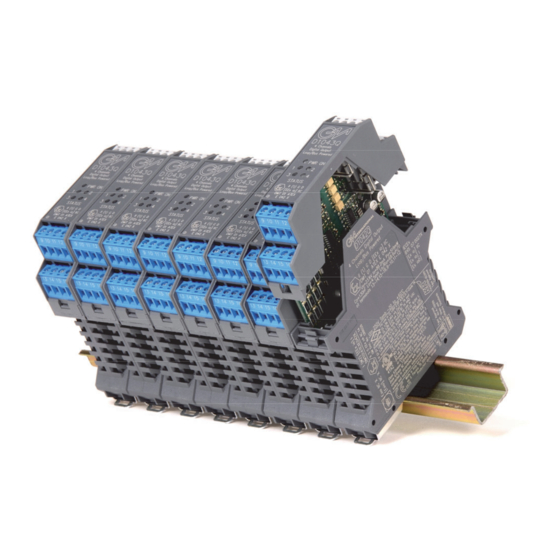
D1000 Power Bus Enclosure Power Supply Voltage 12-24 Vdc can be applied to the module, by connecting directly the voltage to the plug-in Terminal Block of each module, or via the Power Bus System. The system consists of a standard DIN-Rail and modules with Bus Connectors (female on one side and male on the other). - Page 5 Module Enclosure with Power Bus Male Termination Block B+ A - FLT Modbus Fault Power Supply Plug - in terminal block male, Plug - in terminal block male, Plug - in terminal block female, horizontal out, for Power Bus vertical out, for Power Bus horizontal out, for Power Bus Ordering Information: Image...
-
Page 6: Front Panel And Pcb Removal
Front Panel and PCB Removal Front panel and PCB can be plugged out by applying a slight pressure on both sides using a tool. Slowly pull out Front Panel and PCB. The PCB will slide on the enclosure dedicated guides. D1000 series - Intrinsically Safe Isolators Technology for safety... -
Page 7: Terminal Blocks Connection Data
Terminal blocks connection data Grey terminal blocks on Safe Area Blue terminal blocks On Hazardous Area Screwdriver for Trimmers 4 x 1 mm 7 mm Stripping lenght Connection data Conductor cross section solid From 0.2 mm² to 2.5 mm² Conductor cross section stranded From 0.2 mm²... -
Page 8: Mounting And Removing Units From Din-Rail
Mounting and Removing units from DIN-Rail Mounting Fig. 1 Fig. 2 Push engage T35 DIN Rail T35 DIN Rail To mount Series D1000 on 35 mm DIN Rail, hook one side of the mounting foot over the lip of the rail and press down firmly on the barrier (see Fig.1) to snap the other side of the mounting foot over the opposite rail lip (see Fig.2). - Page 9 Fig. 5 Pull and removing from Din-Rail T35 DIN Rail Fig. 7 T35 DIN Rail Dimensions (millimeters) Fig. 6 T35 DIN Rail Technology for safety D1000 series - Intrinsically Safe Isolators...
-
Page 10: D1000 Series Configuration
D1000 Series Configuration The Pocket Portable Configurator type PPC1090 or PPC1092 is suitable to configure the “smart” barrier of D1000 series. The PPC1090/PPC1092 unit is not ATEX, UL or FM approved and is only to be used in Safe Area/Non Hazardous Locations and prior to installation of the isolator and prior to connection of any I.S. - Page 11 D1000 Series Configuration SWC1090 Software The SWC1090 software is designed to provide a PC user interface to configure programmable D1000 modules. It easily allows the user to: Read and write configuration parameters to the units (via COM port); Store and restore data to and from local hard drive for backup or archive; Load factory default configurations;...
-
Page 12: Installation Of Electronic Equipments In Cabinet
Installation of Electronic Equipments in cabinet All electronic equipment operate using electrical power and dissipate part of it into heat which is generally removed by the surrounding ambient air and determines an increase in the operating temperature. High operating temperatures reduce their life and increase the probability of failures according to the Arrhenius criteria, for example an operating temperature increase from 25 to 50 °C can cause a failure rate ten times higher. -
Page 13: Placement Of Isolators In Cabinet
Air Conditioned Cabinets Air conditioned cabinets are preferred in hot climates and / or harsh environments. Cabinet temperature can become equal or even lower than the ambient temperature. A specific refrigerating system or the existing air conditioning system can be used for cabinet conditioning. As an example a cabinet sized 600x600 mm and 2000 mm high has a temperature rise of 10 °C for an installed power of 1000 W. -
Page 14: Heat Dissipation In Cabinets
Heat dissipation in cabinets CLOSED VERSION Natural convection Forced convection by Internal fan (increasing ~ 250 - 300 W In natural convention) ~ 250 - 300 W Forced air circulation Heat dissipation a via air via heat exchanger conditioner (cooling by (air circulation by two temperature lower than separate flows internal... -
Page 15: Calculation Of Radiant Surfaces In Closed Cabinets
Calculation of radiant surfaces in closed cabinets Single cabinet Row of cabinets (all surfaces free of contact) = 1 x A + 2 x A = 2 x N x A + 2 x A + N x A Formula for cabinet with no surfaces in contact with the wall (N = Number of cabinets placed side by side) Formula for row of cabinets with no surface in contact with the wall Single cabinet... -
Page 16: Approvals And Certifications
Approvals and Certifications Intrinsically Safe products G.M. International’s products have been granted IS certificates from the most credited Notified bodies in the world. Certificates are available for ATEX (Europe), IECEX (International), Russian and Ukrainian standards, USA and Canada. Certificates have been integrally scanned and are available for download from our website. SIL Certifications according IEC 61508 and IEC 61511 G.M.
Need help?
Do you have a question about the D1033D and is the answer not in the manual?
Questions and answers