Table of Contents

Related Manuals for GMI D6038D Series


Summary of Contents for GMI D6038D Series
- Page 1 D6038S*, D6038D*, D6038X* INSTRUCTION MANUAL SIL3 Line-Fault Transp. Switch/Prox. Repeater, DIN-Rail and Termination Board Models D6038S*, D6038D*, D6038X* D6038 - SIL3 Line-Fault Transp. Switch/Prox. Repeater G.M. International ISM0431-2...
- Page 2 Characteristics General Description: The Switch/Proximity Detector Repeater D6038 is a module suitable for applications requiring SIL 3 level in safety related systems for high risk industries. The unit can be configured for switches or proximity detectors (EN60947-5-6, NAMUR) and repeats the input state to the output. The output port can assume two different impedance values (RL or RH) or it can open completely.
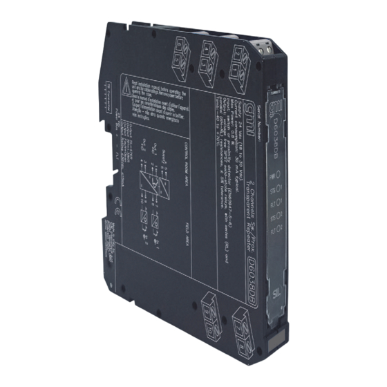
- Page 3 Front Panel and Features SIL 3 (low demand mode of operation) according to IEC 61508:2010 Ed.2 with Tproof = 2 / 5 yrs (≤ 10 / >10 % of total SIF). SC 3: Systematic Capability SIL 3 Field open and short circuit detection ...
- Page 4 Function Diagram MODEL D6038S MODEL D5038S Supply 24 Vdc voltage free voltage free Proximity Contact Contact Out 1 (SIL 3) In 1 Termination board Power and connector Fault Bus MODEL D6038D MODEL D5038D Supply 24 Vdc voltage free voltage free Proximity Contact Contact...
- Page 5 Warning D6038 series must be installed, operated and maintained only by qualified personnel, in accordance to the relevant national/international installation standards. Failure to properly installation or use of the equipment may risk to damage the unit or severe personal injury. The unit cannot be repaired by the end user and must be returned to the manufacturer or his authorized representative.
- Page 6 Configuration A configuration DIP switch is located on component side of PCB. This switch allows the configuration of input/output relationship, fault detection functions and operating mode. Configuration of channel 2 is relevant only for D6038D*. Dip switch factory settings. Switches 1 and 3 are ON, switches 2 and 4 are OFF ON OFF ON OFF Enabled Line fault...
Need help?
Do you have a question about the D6038D Series and is the answer not in the manual?
Questions and answers