
Related Manuals for GMI D1032D


Summary of Contents for GMI D1032D
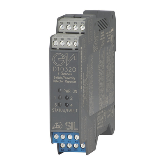
- Page 1 D1032D - D1032Q INSTRUCTION & SAFETY MANUAL SIL 2 Switch/Proximity Detector Repeater Relay Output DIN-Rail Models D1032D, D1032Q D1032 - SIL 2 Switch / Proximity Detector Repeater Relay Output ISM0041-14...
-
Page 2: Technical Data
Power dissipation: 1.8 W for 4 channels D1032Q, 1.4 W for 2 channels D1032D with 24 V supply voltage, input closed and relays energized. Max. power consumption: at 30 V supply voltage, short circuit input and relays energized, 2.4 W for 4 channels D1032Q, 2.0 W for 2 channels D1032D. -
Page 3: Ordering Information
Ordering information Model: D1032 2 channels Power Bus and DIN-Rail accessories: 4 channels DIN rail anchor MCHP065 DIN rail stopper MOR016 Terminal block male MOR017 Terminal block female MOR022 Power Bus enclosure Front Panel and Features SIL 2 according to IEC 61508:2010 Ed.2 for Tproof = 3 /10 years (≤10% / >10 % of total SIF). ... -
Page 4: Terminal Block Connections
Output Ch 3 Input Ch 2 for Voltage free Contact - Input Ch 2 for Proximity Output Ch 4 Input Ch 2 for Voltage free Contact D1032D HAZARDOUS AREA SAFE AREA + Input Ch 1 for Proximity or Output Ch 1-A... -
Page 5: Parameters Table
Parameters Table In the system safety analysis, always check the Hazardous Area/Hazardous Locations devices to conform with the related system documentation, if the device is Intrinsically Safe check its suitability for the Hazardous Area/Hazardous Locations and gas group encountered and that its maximum allowable voltage, current, power (Ui/Vmax, Ii/Imax, Pi/Pi) are not exceeded by the safety parameters (Uo/Voc, Io/Isc, Po/Po) of the D1032 series Associated Apparatus connected to it. -
Page 6: Function Diagram
In 2 6 Common Channels 2-4 Out 3 In 3 2 Common Channels 1-3 Out 4 In 4 6 Common Channels 2-4 MODEL D1032D Supply 24 Vdc voltage free Proximity Contact Out 1-A In 1 2 Common Channel 1 Out 2-A... - Page 7 Closed Safety Function and Failure behavior: D1032D is considered to be operating in Low Demand mode, as a Type A module, having Hardware Fault Tolerance (HFT) = 0. The failure behaviour of D1032D is described by the following definitions: □ fail-Safe State: it is defined as the output being de-energized (so that the output relay is de-energized).
- Page 8 Functional Safety Manual and Application Application for D1032Q OFF operation ON operation Supply Supply 24 Vdc 24 Vdc Out 1 relay is de-energized, Out 1 relay is energized, Field Input: proximity is OFF Field Input: proximity is ON - 4. - 4.
- Page 9 Testing procedure at T-proof The proof test must be performed to reveal dangerous faults which cannot be otherwise detected. This means that it is necessary to specify how dangerous undetected faults, which have been noted during the FMEDA analysis, can be revealed during the proof test. Note for input contacts: to detect a wire break or a short circuit condition, it is necessary to mount, in the input connections and close to the contacts, a 1kΩ...
-
Page 10: Operation
On the section “Function Diagram” and enclosure side a block diagram identifies all connections and configuration DIP switches. Identify the number of channels of the specific card (e.g. D1032D is a dual channel model and D1032Q is a quad channel model), the function and location of each connection terminal using the wiring diagram on the corresponding section, as an example: Connect 24 Vdc power supply positive at terminal “3”... - Page 11 Configuration A configuration DIP Switch is located on component side of pcb. This switch allows the configuration of input/output relationship, fault detection functions and operating mode. Line fault Disabled Setting detection (contact / proximity sensor) Enabled For SIL applications. (proximity sensor or contact with terminating line resistor) Input Output...
- Page 12 Line fault Disabled Setting detection (contact / proximity sensor) Enabled (proximity sensor or contact For SIL applications. with terminating line resistor) Input Output Input Output IN / OUT NO-NE or Operation NC-ND Input Output Input Output NO-ND or NC-NE For SIL applications.
- Page 13 Configuration Dip switch configuration D1032D Side B Panel View Dip switch factory settings CH1-B CH1-A CH1-B ON OFF ON OFF OFF ON OFF ON OFF ON OFF ON CH2-B CH2-A CH2-B Switch 8 positions Line fault Disabled Setting detection Switch 8 positions...
- Page 14 Switch Switch 4 positions 8 positions No Fault Fault ND Mode Output Switch No Fault 8 positions NE Mode D1032D Configuration Summary Table Channel Channel Mode IN/OUT Operation SW1-2 SW2-2 SW2-3 SW1-6 SW1-4 B Output Operation SW2-1 SW2-4 SW1-8 NO-NE or NC-ND...
Need help?
Do you have a question about the D1032D and is the answer not in the manual?
Questions and answers