
Related Manuals for GMI D1000 Series


Summary of Contents for GMI D1000 Series
- Page 1 D1000 Series INSTRUCTION MANUAL D1000 SERIES DIN-RAIL MOUNTING INTRINSICALLY SAFE ISOLATORS D1000 Series - Intrinsically Safe Isolators ISM0102-0...
-
Page 2: Table Of Contents
Placement of Isolators in cabinet ..............................13 Heat dissipation in cabinets ................................14 Calculation of radiant surfaces in closed cabinets ......................... 15 Approvals and Certifications ................................16 Storage ......................................16 Disposal ......................................16 Maintenance and Repair................................16 D1000 series - Intrinsically Safe Isolators Technology for safety... -
Page 3: Mechanical Features
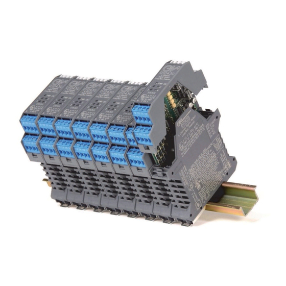
Ultra slim 4 channels 22.5 mm wide DIN-rail mounting modules. 6 mm per channel. Up to 176 I/O channels per meter of DIN-rail. Power Bus enclosure allows a significant reduction in cables, costs and space. Technology for safety D1000 series - Intrinsically Safe Isolators... -
Page 4: D1000 Power Bus Enclosure
DIN-Rail Stopper Module Enclosure with Power Bus Connector female Side B+ A - FLT Modbus Fault Power Supply Module Enclosure with Power Bus Connector male Side FLT A- Power Fault Modbus Supply D1000 series - Intrinsically Safe Isolators Technology for safety... - Page 5 Plug-in terminal block male, horizontal out, for Power Bus Plug-in terminal block female, horizontal out, for Power Bus MOR022 Kit for Bus Mounting: 2 x MOR016, 1 x MOR017, OPT1096 1 x MOR022, 2 x MCHP065 Power Bus Enclosure Technology for safety D1000 series - Intrinsically Safe Isolators...
-
Page 6: Front Panel And Pcb Removal
Front panel and PCB can be plugged out by applying a slight pressure on both sides using a tool. Slowly pull out Front Panel and PCB. The PCB will slide on the enclosure dedicated guides. D1000 series - Intrinsically Safe Isolators Technology for safety... -
Page 7: Terminal Blocks Connection Data
Conductor cross section stranded, with ferrule without plastic sleeve From 0.25 mm² to 2.5 mm² Conductor cross section stranded, with ferrule with plastic sleeve From 0.25 mm² to 2.5 mm² Conductor cross section AWG From 24 to 12 AWG Technology for safety D1000 series - Intrinsically Safe Isolators... -
Page 8: Mounting And Removing Units From Din-Rail
To remove a barrier from the mounting rail, insert the blade screwdriver in the metallic part of the mounting foot and lever the spring catch open against the side of the barrier casing (see Fig.3). D1000 series - Intrinsically Safe Isolators Technology for safety... - Page 9 Fig. 5 Pull and removing from Din-Rail T35 DIN Rail Fig. 7 T35 DIN Rail Dimensions (millimeters) Fig. 6 T35 DIN Rail Technology for safety D1000 series - Intrinsically Safe Isolators...
-
Page 10: D1000 Series Configuration
PPC 1092 Serial Adapter The PPC1092 adapter is needed to interface the PC with D1000 Series modules for a complete configuration of Input, Output and Alarm parameters. The package includes necessary cables and a USB to RS-232 Adapter; a CD-Rom with the SWC1090 Software is also provided. - Page 11 Monitor Input values via USB/COM port; Print a report sheet containing configuration parameters and additional information (see example on the right). The SWC1090 is freely distributed at our website: http://www.gmintsrl.com Example Configuration Report Sheet Technology for safety D1000 series - Intrinsically Safe Isolators...
-
Page 12: Installation Of Electronic Equipments In Cabinet
5 times higher power dissipation than in case 1. As an example a cabinet sized 600x600 mm and 2000 mm high has a temperature rise of 10 °C for an installed power of 1000 W. D1000 series - Intrinsically Safe Isolators Technology for safety... -
Page 13: Placement Of Isolators In Cabinet
The sum of the individual dissipated power of the installed barriers plus other devices need to be below the calculated or given maximum dissipation power of the cabinet. The D1000 series could be installed in horizontal or vertical mounting position. The installation in horizontal position offers an improved heat transport. -
Page 14: Heat Dissipation In Cabinets
~ 1000 W Power value dissipated per ΔT = 10K (single cabinet) For installation in a row of cabinets, power dissipated in the above two examples is decreased of about 5-10% D1000 series - Intrinsically Safe Isolators Technology for safety... -
Page 15: Calculation Of Radiant Surfaces In Closed Cabinets
Formula for cabinet with one side on the wall = 1 x N x A + 2 x A + N x A Formula for row of cabinets with one side on the wall Technology for safety D1000 series - Intrinsically Safe Isolators... -
Page 16: Approvals And Certifications
The majority of our products are SIL certified; reports and analyses from TUV and EXIDA are available for download from our website. Marine Type Approval G.M. International offers Type Approval Certificates for its line of Intrinsically Safe Isolators D1000 Series and Power Supplies for use in Marine and Offshore applications.
Need help?
Do you have a question about the D1000 Series and is the answer not in the manual?
Questions and answers