Table of Contents
Advertisement
Quick Links
Advertisement
Table of Contents

Related Manuals for Astar Tecaris

Summary of Contents for Astar Tecaris
- Page 1 Tecaris Instructions for use...
-
Page 3: Table Of Contents
1. Basic information Contents BASIC INFORMATION ............................... 5 ................................5 ANUFACTURER .............................. 5 ISK MANAGEMENT PROCESS INTENDED USE ................................. 6 ................................6 NTENDED USERS ................................7 SER TRAINING WARRANTY AND MANUFACTURER'S RESPONSIBILITY....................8 OPERATIONAL SAFETY ............................10 ..........................10 AINS SUPPLY AND OPERATION MODE ...................... - Page 4 Figure 4.2 Forced cooling mode screen ........................ 13 Figure 5.1 General view ............................18 Figure 5.2 Left side panel view ..........................19 Figure 5.3 Name plate of Tecaris device ....................... 20 Figure 5.4. UDI code – examples ........................... 21 Figure 6.1 Acclimatization screen ......................... 24 Figure 6.2.
-
Page 5: Basic Information
Read this Instructions for use carefully before starting the unit operation! Follow the recommendations presented in this Instructions for use! The resistive-capacitive radio frequency current physiotherapy unit Tecaris should be installed by the seller. The recipient has the right to insist on the product operation training. -
Page 6: Intended Use
RF therapy cream. Parts of the body intended for treatments with Tecaris are back, upper limb (shoulder, arm, forearm, hand), lower limb (hip, thigh, shank, foot), neck and face for interaction with body tissues such as muscle, skeletal, nervous, circulatory and lymphatic system and/or skin. -
Page 7: User Training
2.2 User training The Tecaris user must be properly trained in the device safe and effective use, before starting the operation. Training in the rules of operation can be carried out by representatives of the manufacturer or seller, based on this Instruction for use. -
Page 8: Warranty And Manufacturer's Responsibility
The manufacturer bears no responsibility for results of faulty installation, wrong diagnosis, wrong use of the device and parts of the unit, failure to observe Instructions for use and performance of repairs by unauthorized persons. Instructions for use - Tecaris page 8 / 60... - Page 9 3. Warranty and manufacturer's responsibility A list of items which may be user replaceable: fuses, • • electrodes, applicators, • neutral electrode cable. • No parts can be serviced or maintained when the device is in use with a patient. The firmware that is part of the device is not intended to be installed, configured or updated by the user.
-
Page 10: Operational Safety
Tecaris is a medical device under safety class I, type BF. The unit may be used only in rooms, where the electric system is executed in compliance with standards in force. The unit is intended for continuous operation. -
Page 11: Storage, Operation And Transport Conditions
Recommendations related to isolation the device from the supply mains: • Do not position the Tecaris so that it is difficult to operate the disconnection of the device from the supply mains. To isolate the device from the supply mains, hold the mains socket-outlet with one hand, grasp the mains •... - Page 12 4. Operational safety Do not position the Tecaris so that it is difficult to operate the disconnection of the device from the supply • mains. • Do not remove warning signs and labels put by the manufacturer on the unit and detachable parts casings.
- Page 13 • Patients with metal, cement or plastic implants should consult with their treating physician. The Tecaris device and other equipment should not be used simultaneously. First and foremost, the • Tecaris device should not be used on patients connected to diagnostic or physiological monitoring equipment.
-
Page 14: Explosion Proof Environment
WARNING: Portable RF communications equipment (including peripherals such as antenna cables and external antennas) should be used no closer than 30 cm (12 inches) to any part of the Tecaris, including cables specified by the manufacturer. Otherwise, degradation of the performance of this equipment could result. -
Page 15: Applied Part
4.7 Essential performance With regard to the Tecaris device, essential performance means the generation of a radio frequency current (300, 500, 750 or 1000 kHz) to raise the temperature locally in the treatment site. The electric current is delivered to the patient by direct contact of electrodes (active and neutral) and a coupling medium, such as RF therapy cream. - Page 16 Active power output 100Ω standard Active power consistent with the rated 100Ω and measurement in the resistive resistor or direct value (tolerance ±20%) oscilloscope or TC- mode measurement using TST-10 tester TC-TST-10 tester Instructions for use - Tecaris page 16 / 60...
-
Page 17: Disposal
4. Operational safety Required Method of Test item Acceptance criteria measuring checking equipment Voltage measurement at Standard load standard load Apparent power output Apparent power consistent with the 100Ω+330pF 100Ω+330pF or measurement in capacitive mode rated value (tolerance ±20%) and oscilloscope or direct TC-TST-10 tester measurement using... -
Page 18: Unit Description
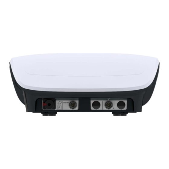
LCD touchscreen, screen is backlit and clearly illustrates and indicates different functions. Tecaris has a plastic enclosure. The unit is equipped with a color touch LCD display with a diagonal of 17.8 cm (7’’). The mains switch, fuse socket and mains socket are located on the left side panel. The detachable parts connection sockets are located on the rear side. -
Page 19: Front Panel
5. Unit description Figure 5.2 Left side panel view 5.2 Front panel 5.2.1 START/STOP key Pressing the START/STOP key results in generation after ending of parameters edition. Pressing START/STOP key while performing a treatment result is treatment interruption and automatically the unit enters the main menu. 5.2.2 CHANGE/STANDBY key Pressing the START/STOP key results in changing the edited parameter in manual or treatment mode. -
Page 20: Name Plate
– UDI-PI code, • nominal voltage and operating frequencies, • types of applied fuses, IP protection class, • manufacturer's data. • Figure 5.3 Name plate of Tecaris device Instructions for use - Tecaris page 20 / 60... -
Page 21: Udi Code
5. Unit description 5.4.1 UDI code Regulation (EU) 2017/745 of The European Parliament and of The Council defines “Unique Device Identifier” (‘UDI’) as a series of numeric or alphanumeric characters that is created through internationally accepted device identification and coding standards and that allows unambiguous identification of specific devices on the market (def.15). -
Page 22: Active Electrodes And Applicator
Active electrodes are detachable parts of the Tecaris device. Active electrodes in the form of disk of various diameters are connected to the applicator. A detachable applicator is connected to its intended output socket in the Tecaris. Active electrodes provided to the Tecaris are intended only for use with this device and its consecutive generations. -
Page 23: Neutral Electrode
5.6 Trolley transport position It is possible to place the Tecaris on a Versa, Versa X or Versa XUVC trolley. These trolleys are equipped in wheels with brakes. To lock the brake, press the lever down (bottom position of the lever). To unlock the brake, release the lever (top position of the lever). -
Page 24: Device Installation And Start-Up
In case of application the other type of trolley or table it is recommended to place the unit at such a height that it would enable convenient operation from the front panel. The light shall enable easy readout of display indicators, however the unit shall not be exposed to direct sunlight. Instructions for use - Tecaris page 24 / 60... -
Page 25: Mounting Of Applicator Holder
6. Device installation and start-up 6.1.1 Mounting of applicator holder There is a possibility to mount the applicator and passive electrode cable holder into the unit's casing. The mounting method is shown in Figure 6.2. Figure 6.2. Holder mounting Recommended position of the detachable parts in the holder is presented in Figure 6.3. Figure 6.3. -
Page 26: Connection Of An Active Electrode Applicator
Put the electrode cover and the silicone insulating cap on the shaft. Connect the electrode by inserting its shaft into the applicator socket – see Figure 6.5. The correct way of mounting the electrode in the applicator is indicated by a "click". Instructions for use - Tecaris page 26 / 60... -
Page 27: Connection Of Neutral (Passive) Electrode
6. Device installation and start-up Figure 6.6 Connection of convex resistive electrode to the applicator To connect the convex resistive electrode: Step Description If you are using a 40mm diameter convex electrode, put the electrode cover and silicone insulating cap on its shaft. Connect the electrode by inserting its shaft into the applicator socket –... -
Page 28: Connection Of Iastm Applicator - Optional
Connect the cable to the plug mounted to the IASTM applicator body (Figure 6.9). Connect the applicator cable to the IASTM socket on the device (Figure 6.10). Secure the plug by tightening protection ring. Instructions for use - Tecaris page 28 / 60... -
Page 29: First Operation
6. Device installation and start-up Warning! Do not disconnect the IASTM applicator and / or cable while generating output signal. When disconnecting the applicator from the unit, do not pull the wire. 6.1.6 First operation Connect the unit to mains supply with delivered detachable mains cable. Switch the mains supply on. After switching the mains supply on proper work of all blocks are tested. -
Page 30: Control Functions
Date of inspection There is possibility to enter into the device the date of the next inspection – it will automatically remind you about the need to perform an annual technical inspection. Instructions for use - Tecaris page 30 / 60... -
Page 31: Information
6. Device installation and start-up 6.2.4.2 Treatment timer There is possibility to configure the interface elements displayed on the treatment screen: • Treatment time – count up – the treatment time will be counted from 00:00 to the set value. The arc representing the passing time increase. -
Page 32: Unit Operation
It is recommended to apply RF therapy cream manufactured by FIAB. • Repeat the cream application during the procedure if: the operator notices that the cream is absorbed quickly, the patient reports a weakened sensation of warmth. Instructions for use - Tecaris page 32 / 60... - Page 33 • The best therapeutic effects are achieved with a combination of Tecaris and manual therapy. Do not start the treatment until the passive electrode is properly positioned. It should be fixed on the •...
-
Page 34: Screen Configuration
Output signal frequency Power level Treatment parameters – described in chapter 8.3 Power level regulation range Treatment time Modulation Note: if the edition field is grayed out, it means that it is inactive. Instructions for use - Tecaris page 34 / 60... -
Page 35: Display Description
7. Unit operation 7.3 Display description The treatment screen appears when the treatment session is started. It presents the most important information about the ongoing therapy. Figure 7.3. Description of the treatment screen Treatment screen: Symbol Description Graphical presentation Treatment parameters (see 8.3) set in manual mode (operation mode, power level and treatment time are editable during treatment) •... -
Page 36: Manual Mode Of Operation
7. Unit operation 7.4 Manual mode of operation The Tecaris unit may operate only in manual mode. Symbol definition and parameters range are given in chapter 8. Operation scheme: Step Description Perform electrodes cleaning and disinfection according to chapter 10.3. -
Page 37: Operation Mode Change
7. Unit operation 7.4.2 Operation mode change The specific nature of radiofrequency current therapy treatments may require changing the operation mode during a single treatment session. In this case, the operator must remember to change the electrode and/or applicator accordingly. Press the "Operation mode"... -
Page 38: Definitions And Parameters
• significant endothermal effect, used in chronic pain or in the production and remodeling phase of the healing process, Instructions for use - Tecaris page 38 / 60... -
Page 39: Operation Modes
The table below presents the clarification of the accepted level of energy emitted by the device in the area of treated type of condition as well as biological and clinical benefits of Tecaris therapy depending on the level of emitted energy. -
Page 40: Treatment Parameters
100% 300 VA 0-30% 75 VA 500 kHz 0-100% 100% 250 VA Capacitive 0-30% 60 VA 750 kHz 0-100% 100% 200 VA 0-30% 45 VA 1 MHz 0-100% 100% 150 VA Instructions for use - Tecaris page 40 / 60... -
Page 41: Maximum Output Voltages And Currents
8. Definitions and parameters Operation Power level Frequency Maximum power delivered to the patient mode regulation range 0-30% 30 W 300 kHz 0-100% 100% 100 W 0-30% 30 W 500 kHz 0-100% 100% 100 W IASTM 0-30% 24 W 750 kHz 0-100% 100% 80 W... -
Page 42: Output Characteristics
8. Definitions and parameters 8.3.4 Output characteristics Description of symbols used in diagrams: Symbol Definition Pout Output power Output control setting Load resistance Pmeas Output power measured Pind Output power indicated by the device Instructions for use - Tecaris page 42 / 60... - Page 43 8. Definitions and parameters 8.3.4.1 CAP mode – diagram showing the power output versus the output control setting at a rated load impedance Rated load: resistance R =100Ω, capacitance C =330pF, serial connection 8.3.4.2 RES and IASTM modes – diagram showing the power output versus the output control setting at a rated load resistance Rated load: resistance R =100Ω...
- Page 44 8. Definitions and parameters 8.3.4.3 RES and IASTM modes – diagram showing the power output over the range of load resistance Setting 100%, output signal frequency 300kHz Setting 50%, output signal frequency 300kHz Instructions for use - Tecaris page 44 / 60...
- Page 45 8. Definitions and parameters Setting 100%, output signal frequency 500kHz Setting 50%, output signal frequency 500kHz page 45 / 60 Issue date 19.06.2023, rev. 2.0...
- Page 46 8. Definitions and parameters Setting 100%, output signal frequency 750kHz Setting 50%, output signal frequency 750kHz Instructions for use - Tecaris page 46 / 60...
- Page 47 8. Definitions and parameters Setting 100%, output signal frequency 1MHz Setting 50%, output signal frequency 1MHz page 47 / 60 Issue date 19.06.2023, rev. 2.0...
-
Page 48: Indications And Contraindications
(lack of sensation, hypesthesia or hyperesthesia at the treatment site) febrile conditions, regardless of etiology • • acute inflammatory conditions tuberculosis • • bacterial or viral infections • epilepsy Instructions for use - Tecaris page 48 / 60... -
Page 49: Application Restrictions
(for treatments in the sacro-lumbar region), • through body orifices (e.g. orally, vaginally, rectally), on parts of the body previously subjected to treatments with Tecaris or other RF therapy device (the interval • time between treatments depends on the used TWS scale): biostimulation TWS 0-3 –... -
Page 50: Maintenance, Cleaning, Disinfection
The manufacturer does not recommend to use any product designated for cleaning screens, because there is no guarantee that the chemicals will not lead to faster wear out of touchscreen layers. Instructions for use - Tecaris page 50 / 60... -
Page 51: Cleaning And Disinfection Of Detachable Parts
10. Maintenance, cleaning, disinfection 10.3 Cleaning and disinfection of detachable parts Clean the detachable parts after each use. Use a soft cloth or paper towel to clean the electrodes of cream residue. Clean detachable parts using a soft cloth or sponge dipped in a mild soap solution or mild detergent. The cloth or sponge should be so drained that squeezing it will not cause dripping. -
Page 52: Troubleshooting
(e.g. “twinge”) Use a proper size of electrode. Verify that enough RF therapy cream has been applied. If the problem persists or frequently occurs, the manufacturer's authorized service center. Instructions for use - Tecaris page 52 / 60... -
Page 53: Fuse Replacement
10. Maintenance, cleaning, disinfection 10.6 Fuse replacement NOTE: Before proceeding to the further described operations isolate the unit from the mains supply! In case of burnt fuses, they must be replaced. Their parameters are given in chapter „Specification and parts of the unit”... -
Page 54: Specification And Parts Of The Unit
700 ÷ 1060 hPa (70 ÷ 106 kPa) Transport conditions: Temperature range: -10 ÷ +45 °C Relative humidity: 20 ÷ 95 % Pressure range: 700 ÷ 1060 hPa (70 ÷ 106 kPa) Instructions for use - Tecaris page 54 / 60... -
Page 55: Emc Parameters
RF transmitters, an electromagnetic site survey should be considered. If the measured field strength in the location in which the Tecaris unit is used exceeds the applicable RF compliance level above, the unit should be observed to verify normal operation. -
Page 56: Standard Parts Of The Unit
11.3 Standard parts of the unit Radio frequency physiotherapy unit Tecaris defined as a medical device contains the controller and parts of the unit. Parts of the unit are not separate medical devices and works only with controllers manufactured by Astar. -
Page 57: Optional Parts Of The Unit
Flat neutral electrode, 24x16 cm A-AT-AST-TCNELOP1 Resistive electrode, 70 mm in diameter A-AT-AST-TCREL70 Capacitive electrode, 70 mm in diameter A-AT-AST-TCCEL70 Shelf for Versa X/ Versa XUVC trolley to accommodate the Tecaris device A-AM-AST-VSXPTC and detachable parts Trolley Versa X A-AM-AST-VSX Trolley Versa XUVC... -
Page 58: Appendix A. Symbol Description
Representation of convex resistive electrode (14 mm and 40 mm) in diameter Date of production: year, symbol ISO 7000-2497 Manufacturer, symbol ISO 7000-3082 IP20 Degree of protection provided by enclosures (IP code), based on IEC 60529 Fuse, symbol IEC 60417-5016 Instructions for use - Tecaris page 58 / 60... - Page 59 Appendix A Symbol Definition Unit version Serial number, symbol ISO 7000-2498 Batch code, symbol ISO 7000-2492 Catalogue number, symbol ISO 7000-2493 Medical device, symbol 5.7.7. of ISO 15223-1 standard Unique Device Identifier, symbol 5.7.10. of ISO 15223-1 standard Disposal of used devices together with other waste is prohibited, complied with the requirements of WEEE Follow Instructions for use, symbol ISO 7010-M002 Background color: blue...
- Page 60 This way up, symbol ISO 7000-0623 The marking of conformity with legal regulations for medical devices applicable in the European Union along with the number of the Notified Body taking part in the conformity assessment. Instructions for use - Tecaris page 60 / 60...
Need help?
Do you have a question about the Tecaris and is the answer not in the manual?
Questions and answers