
Subscribe to Our Youtube Channel
Related Manuals for Ruck Ventilatoren FFH EC Series


Summary of Contents for Ruck Ventilatoren FFH EC Series
- Page 1 Assem b l y a n d Op erati n g M an u a l 137771 FFH...EC, Compact Supply air unit FFH 125 EC 20 FFH 150 EC 20 FFH 160 EC 20 FFH 200 EC 20 English FFH 250 EC 20 FFH 315 EC 20 www.ruck.eu...
- Page 2 The product supplied may therefore differ from the illustration. The original manual has been produced in the German language. Information updated: print 09.06.2021 We reserve the right to make changes ruck Ventilatoren GmbH ruck Ventilatoren GmbH Max-Planck-Str. 5 Max-Planck-Str. 5 D-97944 Boxberg-Windischbuch D-97944 Boxberg-Windischbuch Tel.
-
Page 3: Table Of Contents
English Assembly and Operating Manual Contents Important information ................4 1.1. Rules and regulations ..............4 1.2. Guarantee and liability ..............4 General safety instructions ..............4 2.1. Intended use ..................4 2.2. Improper use ..................5 2.3. Personnel qualifications ..............5 2.4. Safety instructions in this manual .............5 2.5. -
Page 4: Important Information
Planners, plant engineers and operators are responsible for ensuring that the product is installed and operated correctly. Exclusively use ruck Ventilatoren in good technical order and condition. • Check the product for visible defects, for example cracks in the housing or missing rivet, screws and •... -
Page 5: Improper Use
English 2.2. Improper use Any use of the product other than described in chapter “Intended use” is considered as improper. Also note the following points, which are improper and dangerous: Delivery of explosive and flammable media or operation in potentially explosive atmospheres. •... -
Page 6: Adhere To The Following Instructions
English 2.5. Adhere to the following instructions 2.5.1. General instructions Observe the provisions for accident prevention and environmental protection for the country • where the product is used and at the workplace. Persons who assemble, operate, disassemble or maintain ruck products must not consume •... -
Page 7: Safety Labels On The Product
English 2.6. Safety labels on the product FFH 250 EC 20 ErP 2015 400V 3~N max. η=57% (A,static) 50Hz 14,7A 40/40°C 9241W 2940 1/min N= 74,5 60Hz 14,7A 40/40°C 9241W 2940 1/min ISO F VSD integrated SN 201013-Q00000-123 ID 153 376 13.10.2020 Rating plate example FFH 250 EC 20 137771... -
Page 8: Product And Performance Description
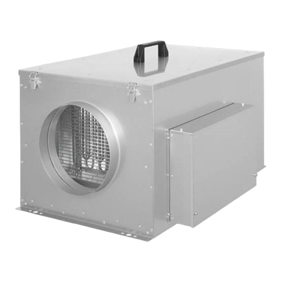
English Product and Performance description The FFH compact supply air unit is a complete, ready-to-use supply air unit with Z-Line air filter, fan, electric heater and integrated control. The unit has a remote control for controlling and setting up the operating parameters. -
Page 9: Transport And Storage
English Transport and storage Transport and storage should only be performed by specialist personnel in accordance with the installation and operating manual and regulations in force. The following points should be noted and followed: Check the delivery according to the delivery note to ensure it is complete and correct and check for •... -
Page 10: Permitted Installation Positions
English 6.1. Permitted installation positions Abb. 6b: Ceiling installation 137771 Abb. 6a: Wall installation, connec- 137771 Abb. 6c: tions upwards. 137771 Wall installation, air flowing upwards. Abb. 6d: Wall mounting connections downwards 6.2. Operating limits 137771 Operating limits indoor installation Fresh air temperature -28 °C to +40 °C Installation place:... -
Page 11: Overcurrent Protection
English Fig. 7: Fig. 8: Connection chamber (1) and cable inlets (2) Connections to the FFH unit. Connection compartment / Connections on the unit 137771 The connection compartment is located in a separate connection box outside the device. The cover 137771 of the connection box can be opened by loosening the 4 screws (see Fig. -
Page 12: Connection Ec-Extract Fan
English 7.2. Connection extract fan It is possible to connect an extract fan (see Fig. 9 and circuit diagram 15.2. Schematics). Connection extract fan Fig. 9: Connection extract fan 137771 Commissioning Electricity warning (hazardous voltage) • Failure to observe the hazard may result in death, injury or damage to property. »... -
Page 13: Operation
English Operation 9.1. Control unit The control unit enables the control and input of the unit‘s various functions. The control unit has an integrated temperature sensor (set-point sensor) for measuring the room temperature. The display shows the various operating parameters and error messages. You can select individual menu points or change values with the various buttons. - Page 14 English a. To enter in the menu keep the ON/OFF key pressed for approx. 4 seconds. b. With the two keys A from left (▲ and ▼) you can move within the current level. c. Use the middle upper key B (▲) to select the menu item. d.
- Page 15 English 9.1.1. Adjustment of the control unit parameter To be able to make changes to the control unit parameter, you must press the „Mode button“ (M) for at least 5 seconds. P 1 will appear on the display. Use button A (▲) to change to your desired parameter.
- Page 16 English 9.1.2. Menu functions control unit Switching the unit on/off on the control unit. Press the ON/OFF button (2) to switch the unit on or off. The unit‘s status now appears on the display with the current values. 21,0° 21,0° »...
- Page 17 English 9.1.3.b. Set current date/time/day of week By pressing the A (▲) and B (▲) keys simultaneously for approx. 5 sec. you will access the menu for 21,0° 21,0° setting the current time, day of the week and date. The display shows the current time and day set. ...
- Page 18 English 9.2. The main menu items Press and hold the ON/OFF key to enter the menu. The individual menu points can be called up with buttons A (▲ and ▼) on the control unit. The keys B (▲ and ▼) can be used to switch to the menu items or to change the values. By holding down the „Mode“...
- Page 19 English 9.2.2. Menu „I/O Status“ ( 01/00/00/00) Display of the values of the individual inputs and outputs. The „M“ key can be used to switch between the standard view (left column) and the service view I/O STATUS (right column). ...
- Page 20 English INPUT Outputs ( 01/02/00/00 ) Analog output to the motor ( 01/02/01/00 ) SUPPLY AIR FAN 11AO01 X20-08 0,0Volt ( 0 – 10V) Digit Relais: Fault (is energized in normal state) FAULT 18RK01 X10 ( 01/02/03/00 ) ...
- Page 21 English 9.2.3. Menu „Process parameters“ ( 02/00/00/00 ) Current process parameters with value. PROCESS PAR. Changeable from access level 2. P1 Minimum set-point value ( 02/01/00/00 ) P 1 MIN-VALUE The parameter P 1 specifies the minimum adjustable setpoint temperature, which you can 17,0 set on the control unit.
- Page 22 English 9.2.4. Menu „System parameters“ ( 03/00/00/00 ) Current system parameters with value. SYSTEM PAR. Settings supply air fan Supply air fan ( 03/01/00/00 ) SUPPLY AIR FAN Settings supply air fan P28 Fan monitoring supply air ( 03/01/01/00 ) NOT INSTALLED = no supply air ...
- Page 23 English 9.2.5. Menu „System setup“ ( 04/00/00/00 ) In this menu the control mode and the external sensors can be configured. SYSTEM CONSTR. This menu item is only visible and changeable from access level 3. For this purpose, the device must ...
- Page 24 English 1.5.1.2. Setting the dead time ( 03/04/08/08 ) LNODE 8 IANA DEADTM 10,0s 1.5.1.3. Setting the measuring range (0V). These settings are to be taken from the measuring range of the transmitter used. ( 03/04/08/09 ) ...
- Page 25 English 9.2.7. Menu „Service“ ( 06/00/00/00 ) Configuration menu for the BUS systems. SERVICE Access level changeable depending Acces level setting ( 06/01/00/00 ) ACCESSLEVEL? 4 Current level is displayed By pressing the middle upper key B (▲) te access level is reset from its default value.
-
Page 26: Additional Functions
English 9.4. Additional functions Start at low external temperatures By switching on the appliance, it can take some time until the electric heating element reaches ope- rating temperature. A special start-up automation will avoid that cold air is blown into the room during this time. -
Page 27: Cleaning And Care
English 10.2. Cleaning and care Servicing, troubleshooting and cleaning may only be performed by specialist personnel in accordance with this installation and operating manual and the regulations in force. If operated correctly, ruck products only require a small amount of maintenance. The following work should be performed at regular intervals, in accordance with health and safety regulations: Check the operation of the control system and safety devices. -
Page 28: Modbus Communication Interface
English 10.3.2. Changing the battery The battery‘s operating capacity is checked when voltage is applied to the unit. A dead battery is indicated by a battery symbol in the status display. Change the battery as follows: Status display Remove the control cable (1) from the control unit. •... -
Page 29: Interface Information
English 11.2. Interface information The device works as a Modbus RTU slave. The interface configuration is 8N1, 9600Baud, slave address 1. The address and the baud rate can be set as described in the chapter „BUS Systems“. As bus line is recommended a twisted pair data cable with 120 Ohm impedance. 11.3. - Page 30 English Register Protocol Autho- Parameter name Value range Data type address rity address 40216 Save parameters 12439 Value change after saving under 0 integer 40233 Min. set point temp. heating Temp. in 1/10°C 100-200 integer 40234 Max. set point temp. heating Value changes to 0 after saving integer 40262 Delta P supply air filter 1...
- Page 31 English Register Protocol Autho- Parameter name Value range Data type address rity address 40436 Set 6 Switching point 6 integer 40437 Set 7 Switching point 1 integer 40438 Set 7 Switching point 2 integer 40439 Set 7 Switching point 3 integer 40440 Set 7 Switching point 4...
-
Page 32: Expansion And Reconfiguration
12. Expansion and reconfiguration The unit must not be reconfigured. ruck Ventilatoren‘s warranty only applies for the configuration delivered. The warranty will cease to apply after any reconfiguration or expansion. 13. Dismantling and disposal Risk of injury if dismantled under hazardous voltage! •... -
Page 33: Troubleshooting
English 14. Troubleshooting Please note the following instructions: Proceed systematically and purposefully when troubleshooting, even when under the pressure of • time. In the worst case, randomly and indiscriminately dismantling and changing settings may result in it no longer being possible to determine the original cause of the fault. Get an overview of the unit‘s operation in conjunction with the overall installation. -
Page 34: Possible Operating Faults
English Fehleranzeige Display Fehlerart und Fehlerbehebung ERROR » The control unit has no reception. » Check the connection or replace the cable if necessary. Supply air temperature sensor fault F1 FAULT » The supply air temperature sensor is defective or the cable is broken. SUPPLY AIR TEMP »... -
Page 35: Technical Data
English 15. Technical data Specifications FFH 125 EC 20 FFH 150 EC 20 FFH 160 EC 20 FFH 200 EC 20 FFH 250 EC 20 FFH 315 EC 20 Units / Mode 153229 153232 153235 153239 153376 153379 Length Width Height without holder Nominal width 25,1... -
Page 36: Appendix
A - In Leistung Temp-In Power A - In +24V Vorsicherung 3 x 16A Fuse Datum 15.01.2020 ruck Ventilatoren GmbH 153225_0 Max-Planck-Strasse 5 Bearb. S. Kuhbach Deckblatt / cover sheet D-97944 Boxberg Gepr. Tel +49 (0) 7930 9211-300 Norm Ursp. - Page 37 Mains voltage Leistung Power Vorsicherung 3 x 16A Fuse +24V +24V +24V A - In 15.01.2020 ruck Ventilatoren GmbH 153225_00 Max-Planck-Strasse 5 S. Kuhbach Deckblatt / cover sheet D-97944 Boxberg Tel +49 (0) 7930 9211-300 Temp-In Ursp. A - In +24V...
- Page 38 400V /3~ / N / 50Hz Mains voltage Leistung Power Vorsicherung 3 x 16A 0-10V Fuse SPEED+ Datum 15.01.2020 ruck Ventilatoren GmbH 153225_0 Max-Planck-Strasse 5 Bearb. S. Kuhbach Deckblatt / cover sheet D-97944 Boxberg Gepr. Tel +49 (0) 7930 9211-300 Norm Ursp.
- Page 39 English zu / close auf / open zu / close auf / open +24V +24V +24V A - In Temp-In D - In +24V www.ruck.eu...
- Page 40 A - Out A - In T 6,3A +24V -X10 Leistung max. 500W -X11 Power max. 500W Datum 15.01.2020 ruck Ventilatoren GmbH Anschluss Abluftventilator Max-Planck-Strasse 5 Bearb. S. Kuhbach D-97944 Boxberg Extract air fan connection Gepr. Tel +49 (0) 7930 9211-300 Änderung...
- Page 41 English Connection pressure sensor for constant pressure control +24V +24V +24V A - In Temp-In D - In +24V www.ruck.eu...
- Page 42 English External sensor (CO2, VOC) +24V +24V +24V A - In Temp-In D - In +24V Tel. +49 7930 9211-0 Fax. +49 7930 9211-150...
- Page 43 English Connection for external control +24V +24V +24V A - In Temp-In D - In +24V www.ruck.eu...
- Page 44 This document, as well as the data, specifica- tions and other information set forth in it, are the exclusive property of ruck Ventilatoren GmbH. It may not be reproduced or given to third par- ties without its consent.
Need help?
Do you have a question about the FFH EC Series and is the answer not in the manual?
Questions and answers