Table of Contents
Advertisement
Sliding Gate Opener User Manual
KND800
KND1600
★ Please read and follow all warnings, precautions and instructions before
installation and use.
★ Periodic checks of the opener are required to ensure safe operation.
★ For residential use only
★ Keep this manual and refer to it when necessary.
★ For installation or troubleshooting assistance visit ausauc.com.au/contact
C030575
VER 21a
Advertisement
Table of Contents

Related Manuals for Kenner KND800


Summary of Contents for Kenner KND800
- Page 1 Sliding Gate Opener User Manual KND800 KND1600 ★ Please read and follow all warnings, precautions and instructions before installation and use. ★ Periodic checks of the opener are required to ensure safe operation. ★ For residential use only ★ Keep this manual and refer to it when necessary.
-
Page 2: Table Of Contents
Table of Contents General Safety ..............................1 Preparation for Installation ..........................2 Parts List ................................4 Optional Accessories Parts List........................5 Technical Specifications & Features ........................ 5 Installation Overview ............................6 Installing the Opener ............................6 Manual operation .............................. 6 Fit the steel reinforced nylon racks ........................ -
Page 3: General Safety
Thank you for purchasing the KENNER sliding gate opener. We are sure that our products will provide satisfaction and trouble free operation as soon as you start to use them. The product is supplied with a user manual which includes installation and safety precautions. These should be read carefully before installation and operation as they provide important information about safety, installation, operation and maintenance. -
Page 4: Preparation For Installation
• The manufacturer declines all responsibility for any consequences resulting from failure to observe Good Technical Practice when constructing closing structures (door, gates etc.), as well as from any deformation which might occur during use. • The manufacturer declines all responsibility for any consequences resulting from improper use of the product, or any use which is different from that expected and specified in this manual. - Page 5 For the sake of safety, a positive stop must be mounted at both ends of ground track.
-
Page 6: Parts List
Parts List... -
Page 7: Optional Accessories Parts List
Optional Accessories Parts List Technical Specifications & Features Specifications KND800 KND1600 Power input: 220~240V/50Hz Motor voltage: 24VDC Rated power: 180W 450W Gate moving speed: 21 cm/s (8.3 in/s) Max torque: 15Nm 30Nm -22℃~ +55℃ (-4°F to 122°F) Environmental conditions: Protection class:... -
Page 8: Installation Overview
· Built in adjustable auto-close (none, 30, 60, 90 Features: seconds) · Pedestrian mode. · Built in max. Motor Running Time (MRT) for · Quick selection for the gate open/close direction multiple safety protection (90 seconds) · Reliable rolling code technology for remote control ·... -
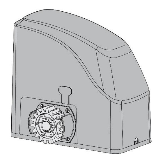
Page 9: Manual Operation
Prior to installing the opener, you should have or build a concrete pad to support the base plate of opener in order to maintain proper stability. The installation proceeds are as follows: 1. Dig a hole for a concrete pad which should be approximately 40 x 24 x 30cm (16”x 9.5”x 12”). -
Page 10: Installing The Magnets
Installing the magnets Before installing the magnets, make sure the gate opener is put in manual operation, (the clutch connected with gear shaft is disengaged) and the mains power supply is disconnected for safety. When viewing the gate from inside the property, no matter whether the gate opens to left or right, the N pole magnet needs to be installed on the left side of the gate, and the S pole magnet needs to be installed on the right side of the gate. -
Page 11: Connecting The Ac Mains Power Supply
* Cut away any rack excess (Note: rack length must be longer than actual travel of the gate) * For Model KND800, thoroughly fasten four M8x60 hexagon self-tapping screws, ensuring the opener is firmly secured on the concrete pad during the whole gate travel. - Page 12 batteries, solar panels, and solar controller by referring to the following illustration. 2. Using batteries without AC electricity The gate opener also can be powered by 2 PCS 12VDC batteries (NOT INCLUDED) as the main power supply with a 24VDC solar panel to charge it. The capacity of the batteries should be at least 12Ah and the power of the solar panel should be at least 30W if no AC electricity will be supplied.
-
Page 13: Connecting The Control Board
Connecting the control board 1. Motor The YELLOW wire of the motor should be connected to the “1” terminal. The RED wire of the motor should be connected to the “2” terminal. 2. Limit Switches The YELLOW wire of the limit switches should be connected to the “3” terminal. The BLACK wire of the limit switches should be connected to the “4”... - Page 14 terminal to the “12” terminal. 5. Push Button The push button should be wired to the “16 and “17” terminals. The polarity does not matter. If the button is pressed repeatedly, the opener will work in the following sequence (open-stop-close-stop-open). 6.
-
Page 15: Setting The Control Board
The BLUE wire of the exit wand should be connected to the “15” terminal. The RED wire of the exit wand should be connected to the “18” terminal. The GREEN wire of the exit wand should be connected to the “19” terminal. The sensitivity adjustment board should be wired to the GREEN wire and the YELLOW wire of the wand. - Page 16 E.g. Running time of the opener in pedestrian mode is 2+4=6 seconds. DIP Switch #3–#5: Fine adjustment of the soft stop period of the motor DIP Switch #3: ON – 1 Second OFF – 0 DIP Switch #4: ON – 2 Seconds OFF – 0 DIP Switch #5: ON –...
-
Page 17: Testing The Reversing Sensitivity
Testing the reversing sensitivity For the sake of safety, it is very important to test the reversing sensitivity as soon as the control board set is finished. The reversing sensitivity adjustment is inversely correlated with the stall force adjustment in potentiometer A and B. -
Page 18: Controlling The Opener With The Remote
Clearing Remote Controls Controlling the opener with the remote • Press button A repeatedly to cycle the opener through the following sequence: (open-stop-close- stop-open). • When the Pedestrian Mode function is enabled, button B is used to operate the opener on Pedestrian Mode (open the gate for the pre-set time). - Page 19 from terminal 1 and 2. Connect the wires to 24V battery directly, the motor should run. Swap the wires, and the motor should run in the opposite direction. If the motor runs in both directions, please check the other parts listed below. 3.
-
Page 20: Maintenance
4. Check the control board. Replace the control board if necessary. 1. If using a photocell, there may be an obstruction or dirt. Clear the photocell and try again. The gate can open, 2. The limit switch may have failed. Use a jumper wire to short terminal 4 with but fails to close. - Page 21 ©2021-2024 KENNER All Rights Reserved www.ausauc.com.au...
Need help?
Do you have a question about the KND800 and is the answer not in the manual?
Questions and answers