Table of Contents
Advertisement
Advertisement
Table of Contents

Related Manuals for Kenner KNL502+


Summary of Contents for Kenner KNL502+
-
Page 2: Table Of Contents
Table of Contents IMPORTANT SAFETY INSTRUCTIONS ......................1 Installation Overview ............................1 Parts List ................................2 Optional Accessories Parts List ........................3 Tools Needed ..............................3 Technical Specifications & Features ........................ 4 Opener Installation ............................5 Opener Dimensions .............................. 5 Step 1: Release the opener .......................... -
Page 3: Important Safety Instructions
Thank you for purchasing our gate opener. We are sure that the products will be greatly satisfying as soon as you start to use it. The product is supplied with a user’s manual which encloses installation and safety precautions. These should be read carefully before installation and operation as they provide important information about safety, installation, operation and maintenance. -
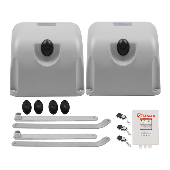
Page 4: Parts List
Parts List... -
Page 5: Optional Accessories Parts List
Optional Accessories Parts List Tools Needed ·Power Drill ·Tape Measure ·Level ·Hammer ·C-Clamps ·Wire Strippers ·Phillips Screwdriver ·Hex Key Wrench – 6mm ·Open End Wrenches - 14# &17# or Adjustable Wrenches ·An extra person should be needed... -
Page 6: Technical Specifications & Features
Technical Specifications & Features Specifications KNL502+ Input: 240V/50Hz Motor voltage: 24VDC Motor Power: 120W each actuator Current: Speed: 90°approximately 18 seconds Max. Gate Open angle: 120° Max. Gate Weight: 600 kgs Max. Gate Length: Duty Cycle: Ambient Temperature: -20℃~ +50℃ (-4°F to 122°F) Protection class: IP44 Notice:Max.Weight and Max.Width per a gate effects only when the gate is correctly and properly installed... -
Page 7: Opener Installation
Opener Installation Prior to beginning the installation of swing Gate opener, We suggest that you become familiar with instructions and illustrations in this manual. This will help insure that your installation is performed in an efficient and professional manner. Opener Dimensions Step 1: Release the opener... -
Page 8: Step 2: Assemble Arms
Step 2: Assemble Arms Step 3: Attach the Arms to Gate Opener Step 4: Determining the mounting positions... -
Page 10: Step 5: Install The Opener's Base Plate
Step 5: Install the Opener’s Base Plate Step 6: Install the Gate Bracket... -
Page 11: Step 7: Set The Limit Switches Of The Opener At Left Side
Step 7: Set the Limit Switches of the opener at left side Set the left closed Limit Switch: Loosen the screw of Bottom Collar. Push the left gate to closed position. Rotate the Bottom Collar until after hearing a click of Bottom Limit Switch’s contact. And then tighten the screw of Bottom Collar. Set the left opened Limit Switch: Loosen the screw of Top Collar. -
Page 12: Step 8: Set The Limit Switches Of The Opener At Right Side
Step 8: Set the Limit Switches of the opener at right side Set the right closed Limit Switch: Loosen the screw of Top Collar. Push the right gate to closed position. Rotate the Top Collar until after hearing a click of Top Limit Switch’s contact. And then tighten the screw of Top Collar. Set the right opened Limit Switch: Loosen the screw of Bottom Collar. -
Page 13: Mounting The Control Box
Mounting the Control Box Step 1 To install the control box use the deck screws (not provided). Ensure the control box is installed in a secure surface and at least 100 cm (40 inches) above the ground to protect it from rain, snow, etc. - Page 14 NOTE: Only motor cables (1.5m length) are provided. Other cables are subject to site installation requirement and not provided. CAUTION: Make sure the cable outlet hole in the Control Box is always down during installation so as to drain off the water.
-
Page 15: Connecting Of The Control Board (For Pull To Open)
Connecting of the control board (For Pull to Open) - Page 16 Note: Ensure the power is OFF before the connecting of the control board. Note: You should use the five core cable with PVC sheath to connect the articulated arm to the main control board. Wires in the five core cable used to connect the motor should be greater than (16AWG).
-
Page 17: How To Learn Or Erase The Remote
The BROWN wire of the external receiver should be connected into the “19” terminal. The BLACK wire of the external receiver should be connected into the “20” terminal. The RED wire of the external receiver should be connected into the “9” terminal. Wired Keypad (24VDC) (optional) The RED wire of the wired keypad should be connected into the “9”... -
Page 18: Setting Of The Control Board
Setting of the Control Board 1. Check again for completed and correct assembly of your swing gate opener and gate. Plug the Power Cord into the nearest AC outlet. The Digital Display on the Control Board will flash with “- -”. The unit is in standby. - Page 19 “P5”. Now Close Interval Set is finished. 6. Adjust the Obstruction Sensitivity/Stall Force When the Digital Display indicates “P5”, the gate opener is on the Stall Force Adjustment. Without a properly installed safety reversal system, person (particularly small children) could be SERIOUSLY INJURED or KILLED by a closing gate.
- Page 20 Press the “FUNC” button to store the data when you finish setting. The Digital Display will indicate “P9”. Now MOTOR2 adjustment is finished. 8. Set the Safety Photocell Beam System (PBS) (Optional) When the Digital Display indicates “P9”, the gate opener enters PBS set mode. You can press and release the “INC”...
-
Page 21: Indicate Illustration On The Digital Display When Gate Opener Is Running
13. If all of data is set and no other change needed, press “FUNC” Button. “- -” appears on the Digital Display, and the opener enters standby mode. Indicate Illustration on the Digital Display When Gate Opener is Running The RIGHT image on Digital Display symbolizes motor of ARM 1 when the gate opener is running. The LEFT image on Digital Display symbolizes motor of ARM 2. - Page 22 Connection of arm 2(Installed in the right side ) The MOTOR+ terminal of the arm should be connected to the MOTOR2- terminal of the control board. MOTOR- terminal should connected to the +MOTOR2 terminal of the control board. The DN terminal should be connected to the DLT2 terminal of the control board.
-
Page 23: Maintenance
Maintenance Warning: Disconnect power before servicing. 1. Using a clean, dry cloth, wipe the gate opener shaft, and then apply a silicone spray to reduce its friction. In cold climates where temperatures reach 1°C (30°F) or less, spray silicone on the actuator every 4~6 weeks to prevent freeze up. - Page 24 Ensure that the motor cable is away from sources of electrical interference, such as electric fences, power lines etc. 6. Gate opens, closes or stops on its own Ensure that the key for manual release is in the lock position. Refer to page 24.
-
Page 25: Quick-Setting Guide
Quick-Setting Guide...
Need help?
Do you have a question about the KNL502+ and is the answer not in the manual?
Questions and answers