
Subscribe to Our Youtube Channel
Related Manuals for Black Box ME570A-MST


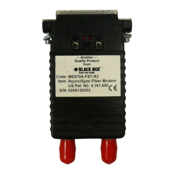
Summary of Contents for Black Box ME570A-MST
- Page 1 © Copyright 1999. Black Box Corporation. All rights reserved. 1000 Park Drive • Lawrence, PA 15055-1018 • 724-746-5500 • Fax 724-746-0746...
- Page 2 Order toll-free in the U.S. 24 hours, 7 A.M. Monday to midnight Friday: 877-877-BBOX SUPPORT FREE technical support, 24 hours a day, 7 days a week: Call 724-746-5500 or fax 724-746-0746 INFORMATION Mail order: Black Box Corporation, 1000 Park Drive, Lawrence, PA 15055-1018 Web site: www.blackbox.com • E-mail: info@blackbox.com...
- Page 4 ASYNC/SYNC FIBER OPTIC MODEM AND FO MODEM CARD FEDERAL COMMUNICATIONS COMMISSION INDUSTRY CANADA RADIO FREQUENCY INTERFERENCE STATEMENTS This equipment generates, uses, and can radiate radio frequency energy and if not installed and used properly, that is, in strict accordance with the manufacturer’s instructions, may cause interference to radio communication.
- Page 5 ASYNC/SYNC FIBER OPTIC MODEM AND FO MODEM CARD NORMAS OFICIALES MEXICANAS (NOM) ELECTRICAL SAFETY STATEMENT INSTRUCCIONES DE SEGURIDAD 1. Todas las instrucciones de seguridad y operación deberán ser leídas antes de que el aparato eléctrico sea operado. 2. Las instrucciones de seguridad y operación deberán ser guardadas para referencia futura.
- Page 6 ASYNC/SYNC FIBER OPTIC MODEM AND FO MODEM CARD 11. El aparato eléctrico deberá ser connectado a una fuente de poder sólo del tipo descrito en el instructivo de operación, o como se indique en el aparato. 12. Precaución debe ser tomada de tal manera que la tierra fisica y la polarización del equipo no sea eliminada.
- Page 7 ASYNC/SYNC FIBER OPTIC MODEM AND FO MODEM CARD FCC REQUIREMENTS FOR TELEPHONE-LINE EQUIPMENT 1. The Federal Communications Commission (FCC) has established rules which permit this device to be directly connected to the telephone network with standardized jacks. This equipment should not be used on party lines or coin lines.
- Page 8 ASYNC/SYNC FIBER OPTIC MODEM AND FO MODEM CARD CERTIFICATION NOTICE FOR EQUIPMENT USED IN CANADA The Canadian Department of Communications label identifies certified equipment. This certification means that the equipment meets certain telecommunications-network protective, operation, and safety requirements. The Department does not guarantee the equipment will operate to the user’s satisfaction.
- Page 9 ASYNC/SYNC FIBER OPTIC MODEM AND FO MODEM CARD TRADEMARKS ® is a registered trademark of AT&T. Any other trademarks mentioned in this manual are acknowledged to be the property of the trademark owners.
-
Page 10: Table Of Contents
ASYNC/SYNC FIBER OPTIC MODEM AND FO MODEM CARD Contents Chapter Page 1. Specifications ..........8 2. -
Page 11: Specifications
ASYNC/SYNC FIBER OPTIC MODEM AND FO MODEM CARD 1. Specifications Transmission Line — Dual optical cable Transmission Mode — Async or sync, half- or full-duplex Interface — EIA RS-232, CCITT V.24 Data Rates — Up to 38.4 kbps Distance — 2 miles (3.2 km) over continuous fiber RTS/CTS Delay —... -
Page 12: Introduction
ASYNC/SYNC FIBER OPTIC MODEM AND FO MODEM CARD 2. Introduction 2.1 Description The Async/Sync Fiber Optic Modem is a miniature modem that combines the noise immunity of fiber with the troubleshooting capabilities of V.52 and V.54 diagnostics. The modem operates in asynchronous or synchronous mode and supports data rates to 38.4 kbps. -
Page 13: Configuration
The Async/Sync Fiber Optic Modem is fairly simple to install and easy to operate: just set it and forget it. The instructions in this chapter will help you set up the modem properly. If you have questions, call Black Box Technical Support at 724-746-5500. - Page 14 ASYNC/SYNC FIBER OPTIC MODEM AND FO MODEM CARD 1 2 3 4 5 6 7 8 1 2 3 4 5 6 7 8 Figure 3-1. DIP Switches on the Async/Sync Fiber Optic Modem. The Async/Sync Fiber Optic Modem has two 8-position DIP switches (S1 and S2) for configuration.
-
Page 15: Configuration Switch Set S1
ASYNC/SYNC FIBER OPTIC MODEM AND FO MODEM CARD 1 2 3 4 5 6 7 8 Figure 3-2. Close-up of DIP Switches Showing “ON” and “OFF” Positions. 3.2 Configuration Switch Set S1 The DIP switches on S1 set data rate, clock source, async/sync mode, and carrier-control method. -
Page 16: S1-1 Through S1-4: Data Rate Setting
ASYNC/SYNC FIBER OPTIC MODEM AND FO MODEM CARD 3.2.1 S1-1 T S1-4: D HROUGH Switches S1-1 through S1-4 are set in combination to determine the data rate for the Async/Sync Fiber Optic Modem. Table 3-2. Data Rate Settings. S1-1 S1-2 S1-3 S1-4 Setting... -
Page 17: S1-7: Asynchronous/Synchronous Mode
ASYNC/SYNC FIBER OPTIC MODEM AND FO MODEM CARD 3.2.3 S1-7: A SYNCHRONOUS YNCHRONOUS The setting for switch S1-7 determines whether the Async/Sync Fiber Optic Modem is in asynchronous or synchronous operating mode. Table 3-4. Async/Sync Settings. S1-7 Setting Asynchronous* Synchronous *Default 3.2.4 S1-8: C ARRIER... -
Page 18: S2-1 And S2-2: Word Length
ASYNC/SYNC FIBER OPTIC MODEM AND FO MODEM CARD 3.3.1 S2-1 S2-2: W ENGTH Switches S2-1 and S2-2 are set in combination to determine the word length for asynchronous data. Table 3-7. Word-Length Switch Settings. S2-1 S2-2 Setting 8 bits 9 bits 10 bits* 11 bits *Default... -
Page 19: S2-8: V.54 Loopback Test Enable
ASYNC/SYNC FIBER OPTIC MODEM AND FO MODEM CARD 3.3.5 S2-8: V.54 L OOPBACK NABLE To reset the V.54 circuit, set switch S2-8 to the “On” position, then back to the “Off” position. Table 3-10. V.54 Settings. S2-8 Setting V.54 Enable* V.54 Disable *Default... -
Page 20: Installation
ASYNC/SYNC FIBER OPTIC MODEM AND FO MODEM CARD 4. Installation The Async/Sync Fiber Optic Modem is easy to install. After configuring the DIP switches, simply connect the two fiber cables and then connect the RS-232 interface. Figure 4-1 shows the location of the fiber connections on the rear panel. Fiber Fiber Figure 4-1. -
Page 21: Operation
ASYNC/SYNC FIBER OPTIC MODEM AND FO MODEM CARD 5. Operation Once you have configured each Async/Sync Fiber Optic Modem properly and connected the fiber and RS-232 cables, you are ready to operate the Modems. LEDs Figure 5-1. LEDs. 5.1 Test Modes The Async/Sync Fiber Optic Modem offers two V.54 test modes to evaluate the condition of the modems and the communication link. -
Page 22: Local Analog Loopback (Lal)
The Test LED should be lit. 2. Verify that the data-terminal equipment is operating properly and can be used for a test. If a fault is indicated, call Black Box Technical Support at 724-746 5500. 3. Perform a BER (bit error rate) test on each modem. If the BER test equipment indicates no faults, but the data terminal indicates a fault, follow the manufacturer’s checkout procedures for the data terminal. -
Page 23: Using The V.52 Ber Test Independently
ASYNC/SYNC FIBER OPTIC MODEM AND FO MODEM CARD 3. If the BER test equipment indicates a fault, and the Local Analog Loopback test was successful for both modems, you may have a problem with the twisted- pair line between the modems. Check the fiber line for proper connections and continuity. -
Page 24: Appendix: Pin Configuration
ASYNC/SYNC FIBER OPTIC MODEM AND FO MODEM CARD Appendix: Pin Configuration Table A-1. Pin Configuration for the DB25 Connector. DIRECTION STANDARD RS-232C/V.24 “DCE” SETTING DIRECTION (FG) FRAME GROUND TO MODEM (TD) TRANSMIT DATA TO 1070RC FROM 1070RC TRANSMIT CLOCK FROM MODEM (RD) RECEIVE DATA FROM 1070RC TO MODEM... - Page 25 ASYNC/SYNC FIBER OPTIC MODEM AND FO MODEM CARD Table A-2. Pin Configuration for the HD DB26 Connector. Pin: Signal Pin: Signal 1: Frame Ground 8: CD 2: TD 15: TC 3: RD 17: RC 4: RTS 18: LAL 5: CTS 20: DTR 6: DSR 21: RDL...
Need help?
Do you have a question about the ME570A-MST and is the answer not in the manual?
Questions and answers