Table of Contents
Advertisement
Quick Links
Advertisement
Table of Contents

Subscribe to Our Youtube Channel
Related Manuals for PairGain PRL-770


Summary of Contents for PairGain PRL-770
- Page 1 PG-P EMOTE Model List Number Part Number CLEI Code PRL-770 150-1670-11 S9MSAA0ARA ECHNOLOGIES NGINEERING ERVICES ECHNICAL RACTICE 950-770-100 ECTION Revision History of this practice. Revision 01—March 14, 1997 A) Initial Release...
-
Page 2: Table Of Contents
A caution warns you of possible damage to equipment. A warning indicates the possibility of personal injury. ©Copyright 1997 PairGain Technologies, Inc. PairGain is a registered trademark, and PG-Plus is a trademark of PairGain Technologies, Inc. Page ii PairGain Engineering - Plant Series... -
Page 3: Product Overview
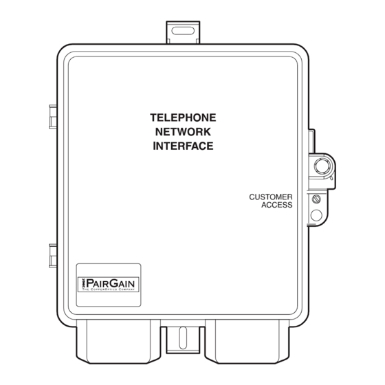
DS0 channels from the HDSL line to the individual subscriber circuits, and can be located up to 31.2 kft (22 gauge wire) from the COT shelf. The PRL-770 operates at a nominal HDSL line rate of 261.3 kbps. - Page 4 Protected Termination Module door (Figure 3). In either case, you have full access to the interior of the PRL-770 and to each Protected Termination Module by removing the Telco override screw from the Customer Access door, or by removing the two tamper-proof screws from the Telco Access door.
- Page 5 950-770-100 March 14, 1997 Revision 01 Figure 2. Securing the Customer Access Door Figure 3. Securing a Protected Termination Module PG-Plus PRL-770 PairGain Engineering-Plant Series Page 3...
-
Page 6: Specifications
POTS............Screw Terminals on RJ-11 line interface POTS Interface Analog Impedance........600 Ω PRL-770 remote unit Supervisory Range ..100 Ω plus 430 Ω for handset Detection of Loop Open......> 10 kΩ Idle State Voltage ........-48V (minimum) Loop Current ..........23 mA (minimum) Ring Generation.......... -
Page 7: Installation And Test
PRL-770 by applying + 100 V dc to the HDSL pair. The COLU also initiates a start-up after a momentary short has been applied to the HDSL pair. The COLU responds with start-up voltage immediately upon removal of the short. - Page 8 Install the PRL-770 RT Enclosure. Use the two #10 x 1.5" wood screws and flat washers provided in the PRL-770 Mounting Kit to attach the PRL-770 RT enclosure to the side of the customer residence (see Figure 4). For installation on stucco or other suitable surface, use the two PairGain provided #10 x 1"...
- Page 9 PRL-770 Reference Label. During installation, refer to the PRL-770 reference label (Figure 5) affixed inside the Customer Access door. The middle section of the PRL-770 reference label identifies the Frame Ground and HDSL Tip and Ring wires as well as the wire color code for the four POTS lines.
- Page 10 Attach the Frame-Ground Wire: Use a 5/32" tamper-proof hex key to loosen the two tamper-proof screws on the Telco Access door, then open the Telco Access door (Figure 6). Figure 6. Opening the Telco Access Door Page 8 PairGain Engineering-Plant Series PG-Plus PRL-770...
- Page 11 PRL-770 RT enclosure (Figure 7). Figure 7. Attaching the Frame-Ground Wire Insert the frame-ground wire into the PRL-770 RT enclosure through the pencil hole made in step 1. A 10 AWG copper frame ground wire is recommended.
- Page 12 Use a pencil to punch a second small hole in the bottom of the rubber grommet on the left-hand bottom side of the PRL-770 RT enclosure. Insert the HDSL Tip and Ring wires into the pencil hole made in step 1.
- Page 13 Connect the Tip conductor to the green terminal lug on the Protected Termination Module. Connect the Ring conductor to the red terminal lug on the Protected Termination Module. Figure 10. Attaching the POTS Wire Pair PG-Plus PRL-770 PairGain Engineering-Plant Series Page 11...
-
Page 14: Turn Up And Testing
The following start-up sequence should occur: The COLU responds with start-up voltage immediately. The PRL-770 detects HDSL line voltage, drops the metallic fallback to POTS, then initiates the HDSL start-up sequence. The POWER LED flashes green and the ACTIVITY LED is solid green. -
Page 15: Fault Isolation
The Status LEDs indicate different system states such as status of power, and subscriber line activity including on-hook, off-hook, ringing, and subscriber drop test activity. The top portion of the PRL-770 reference label provides a guide to what the Status LEDs indicate (Figure 11). Figure 11. PRL-770 Status Window... -
Page 16: Technical Support
Transmission speeds up to 28.8 kbps are supported with a character format of 8-N-1. 10. Certification 10.1 FCC Compliance. The PG-Plus PRL-770 Remote Line unit complies with the limits for a Class B digital device, pursuant to Part 15 of the FCC rules. These limits are designed to provide reasonable protection against harmful interference in a residential installation. -
Page 17: Warranty
11. Warranty 11.1 PairGain Technologies warrants this product to be free of defects and to be fully functional for a period of 60 months from the date of original shipment, given proper customer installation and regular maintenance. PairGain will repair or replace any unit without cost during this period if the unit is found to be defective for any reason other than abuse or improper use or installation.
Need help?
Do you have a question about the PRL-770 and is the answer not in the manual?
Questions and answers