Table of Contents
Advertisement
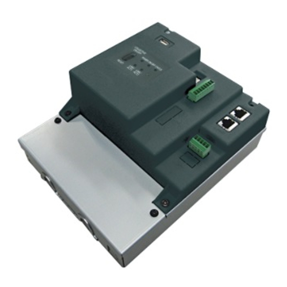
Air Conditioning Control System
Centralized Controller
TW-50A
or
CAUTION, depending on the severity
of possible consequences that may result
when the instructions are not followed
exactly as stated.
Proper installation is important for your
safety and proper functioning of the units.
Thoroughly read the following safety
precautions prior to installation.
Before installing the controller, please read this Installation Manual carefully to ensure proper operation.
Retain this manual for future reference.
Installation and Instructions Manual
Contents
1. Safety precautions ..................................................... 2
1-1. General precautions ..............................................................2
1-2. Precautions for unit installation .............................................3
1-3. Precautions for electrical wiring ............................................3
1-4. Precautions for relocating or repairing the unit .....................4
1-5. Additional precautions ...........................................................4
2. Introduction ................................................................ 6
2-1. Part names ............................................................................6
3. Package contents ....................................................... 8
4. Specifications ............................................................. 9
4-1. Product specifications ...........................................................9
4-2. External dimensions ............................................................10
5. Installation .................................................................11
5-1. Items not included ...............................................................12
5-2. Items sold separately ..........................................................12
5-3. Installation space ................................................................13
5-4. Installation procedures ........................................................14
6. Wiring connections ................................................... 17
6-1. Removing/reinstalling the service cover ..............................17
cables ..................................................................................19
6-3. Connecting the LAN cable ..................................................21
6-4. Confirming the LAN transmission delay time ......................21
7. Initial settings ........................................................... 23
7-1. Initial settings ......................................................................23
7-2. Quick IP address (LAN1) setting .........................................24
7-3. Network settings ..................................................................25
8. Test run .................................................................... 26
8-1. Collective operation ON/OFF ..............................................26
9. External input/output ................................................ 27
9-1. External signal input/output function ...................................27
9-2. Pulse signal input function ..................................................29
10. Maintenance ............................................................. 30
10-1. Inspection and maintenance .............................................30
10-2. Back up/import settings data .............................................31
10-3. Software update ................................................................35
10-4. Software information .........................................................38
<ORIGINAL>
Advertisement
Table of Contents

Related Manuals for Mitsubishi Electric TW-50A


Summary of Contents for Mitsubishi Electric TW-50A
-
Page 1: Table Of Contents
<ORIGINAL> Air Conditioning Control System Centralized Controller TW-50A Installation and Instructions Manual Contents 1. Safety precautions ............. 2 1-1. General precautions ..............2 1-2. Precautions for unit installation ..........3 1-3. Precautions for electrical wiring ..........3 1-4. Precautions for relocating or repairing the unit .....4 1-5. -
Page 2: Safety Precautions
1. Safety precautions ►Thoroughly read the following safety precautions prior to installation. ►Observe these precautions carefully to ensure safety. ►After reading this manual, pass the manual on to the end user to retain for future reference. ►The user should keep this manual for future reference and refer to it as necessary. This manual should be made available to those who repair or relocate the units. -
Page 3: Precautions For Unit Installation
To reduce the risk of fire or explosion, do not place flammable materials or use flammable sprays around the controller. To reduce the risk of electric shock or malfunction, do not touch the switches or buttons with a sharp object. To reduce the risk of injury, electric shock, or malfunction, avoid contact with the sharp edges of certain parts. -
Page 4: Precautions For Relocating Or Repairing The Unit
Electrical work must be performed by qualified personnel in accordance with local regulations and the instructions provided in this manual. Only use specified cables and dedicated circuits. Inadequate power source capacity or improper electrical work will result in electric shock, malfunction, or fire. To reduce the risk of electric shock, install an overcurrent breaker and an earth leakage breaker on the power supply. - Page 5 Take appropriate measures against electrical noise interference when installing the controller in hospitals or radio communication facilities. Inverter, high-frequency medical, or wireless communication equipment as well as power generators may cause the air conditioning system to malfunction. The air conditioning system may also adversely affect the operation of these types of equipment by creating electrical noise.
-
Page 6: Introduction
2. Introduction TW-50A is a total management system. Any connected air conditioning systems can be operated or monitored on the Web browser. TW-50A can also be used as an expansion controller of TE-200A. By connecting TE-200A, up to 200 indoor units and other equipment can be controlled. - Page 7 * Back side with the service cover removed LAN1 LAN2 (Unused) (Unused) CN21 Ground Item Description IP addresses can be easily set with SW1. Refer to section 7-2 “Quick IP address (LAN1) setting” for details. LAN1 Connects to other units of equipment over the LAN via a HUB. Connects to the Building Management System over the LAN (BACnet ®...
-
Page 8: Package Contents
3. Package contents The following items are included in the package. Package contents Qty. TW-50 Connector (CN6) (Unused) Connector (CN7) (Used for pulse input) L-fitting DIN rail attachment (for attaching DIN rail of 35 mm (1-7/16 in) width) DIN rail auxiliary bracket Roundhead screw (M3 ×... -
Page 9: Specifications
4. Specifications 4-1. Product specifications Item Specifications Power supply 100–240 VAC ± 10%; 50/60 Hz Single-phase M-NET power feeding coefficient Network interface 100BASE-TX Operating temperature -10°C – +55°C (+14°F – +131°F) range Temperature Ambient Storage temperature conditions -20°C – +60°C (-4°F – +140°F) range Humidity 30%–90% RH (Non-condensing) -
Page 10: External Dimensions
4-2. External dimensions (1) When using L-fittings Unit: mm (in) L-fitting (supplied) (1-9/16) 100 (3-15/16) L-fitting 169 (6-11/16) 92 (3-10/16) (supplied) 172 (6-13/16) (2) When using DIN rail 23 (15/16) 150 (5-15/16) DIN rail DIN rail attachment (supplied) DIN rail auxiliary 46 (1-13/16) bracket (supplied) -
Page 11: Installation
5. Installation Test runs, inspection, and service must be performed by qualified personnel in accordance with this manual. Incorrect use may result in injury, electric shock, malfunction, or fire. Do not install the controller where there is a risk of flammable gas leaks. If flammable gas accumulates around the controller, it may ignite and cause a fire or explosion. -
Page 12: Items Not Included
5-1. Items not included The following items are required to install the TW-50. Items not included Specifications Locknuts and bushing Must be suitable for the conduit tube to be used. M3.5 ring terminal (for AC power cables (L/L1, N/L2) and M-NET transmission cables (A, B, Sleeved ring terminal M4 ring terminal (for protective ground wire) Type: Sheathed cable (should not be lighter than ordinary sheathed cable IEC 60227.) -
Page 13: Installation Space
5-3. Installation space The TW-50 must be installed inside the metal control box. Either the supplied L-fittings or DIN rail attachments can be used for the installation. Leave a space around the TW-50 as shown in the figure below. Unit: mm (in) 50 (2) 50 (2) 50 (2) -
Page 14: Installation Procedures
5-4. Installation procedures Note ● Connect the necessary cables and wires before installing TW-50, referring to chapters 6 and 9. ● Do not install the unit where the unit may continuously receive vibration. The continuous vibration may cause the connectors to disconnect. - Page 15 5-4-2. Method 2: Installation using DIN rail 1. Have a metal control box ready. 2. Attach the supplied two DIN rail attachments to the TW-50 with the supplied roundhead screws (M3 × 12). 3. Attach the supplied DIN rail auxiliary bracket to the TW-50 with the supplied roundhead screws (M3 × 6). TW-50 DIN rail attachment (supplied)
- Page 16 [Mounting/removing the TW-50 on/from the DIN rail] Mounting Removing (1) Mounting 1. Hook the upper side of the attachments to the DIN rail. 2. Push the lower part of the TW-50 until it snaps into place. Note ● Ensure that the DIN rail attachments are fixed securely in place to the DIN rail. (2) Removing 1.
-
Page 17: Wiring Connections
6. Wiring connections To reduce the risk of malfunction, smoke, fire, or damage to the controller, do not connect the power cable to the signal terminal block. To reduce the risk of injury or electric shock, switch off the main power before performing electrical work. - Page 18 (2) Reinstalling 1. Insert the AC power cables and M-NET transmission cables into the openings, and then insert the hooks to the openings. Note: Do not pinch the cables between the TW-50 body and the service cover. 2. Screw down the service panel with the two fixing screws. 3.
-
Page 19: Connecting Ac Power Cables And M-Net Transmission
6-2. Connecting AC power cables and M-NET transmission cables TW-50 Outdoor unit Overcurrent breaker M-NET transmission cables Earth leakage breaker for centralized control 100–240 VAC AC power cables 6-2-1. AC power cables and protective ground wire 1. Attach M3.5 sleeved ring terminals to the AC power cables, and attach an M4.0 sleeved ring terminal to the protective ground wire. - Page 20 6-2-2. M-NET transmission cables (Centralized control transmission cables) 1. Attach M3.5 sleeved ring terminals to the M-NET transmission cables (A, B, Shield). 2. Connect the M-NET transmission cables to the M-NET terminal block. 3. Fix the cables in place with the supplied cable tie. 4.
-
Page 21: Connecting The Lan Cable
6-3. Connecting the LAN cable To prevent unauthorized access, always use a security device such as a VPN router when connecting to the Internet. Connect the LAN cable to the LAN1 port on the TW-50. (The LAN2 port is exclusively used for BACnet function.) ®... - Page 22 (2) Checking the transmission delay time ① Click [Start]>[Program]>[Accessories]>[Command Prompt] on the monitoring PC. * The procedure may vary depending on the OS. ② Enter [ping (IP address of TE-200/TE-50/TW-50)], and press the Enter key. ([ping -w 4000 192.168.1.1] is entered on the sample screen below.) ③...
-
Page 23: Initial Settings
7. Initial settings Initial settings need to be made for each TW-50 on the Initial Setting Tool or Integrated Centralized Control Web. Details about the initial settings and other settings and operations are covered in the Instruction Book (Initial Settings). Note: To monitor and operate the air conditioning units on the Web browser (Integrated Centralized Control Web), settings need to be configured on the Initial Setting Tool. -
Page 24: Quick Ip Address (Lan1) Setting
7-2. Quick IP address (LAN1) setting When connecting a TW-50 to a dedicated LAN system, IP address (LAN1) of the TW-50 can be easily set to an address between 192.168.1.1 and 192.168.1.15 with rotary switch SW1. When the IP address cannot be set with rotary switch SW1 (e.g., when connecting a TW-50 to an existing LAN, when the TW-50 is used as an expansion controller of TE-200), set the IP address on the Initial Setting Tool or the Web Browser for Initial Settings. -
Page 25: Network Settings
7-3. Network settings IP, subnet mask, and gateway addresses can be set on the Initial Setting Tool or the Web Browser for Initial Settings. Rotary switch SW1 must be set to “0” (default setting) to make these settings. When connecting the TW-50 to an existing LAN, consult the system administrator to decide the IP, subnet mask, and gateway addresses. -
Page 26: Test Run
8. Test run 8-1. Collective operation ON/OFF Confirm that the group settings and interlock settings are complete before performing a test run. It may take approximately five minutes from power on until the local remote controllers become operable. Refer to the indoor unit Installation Manual for details about a test run. Note: Perform a test run in the presence of a customer. -
Page 27: External Input/Output
9. External input/output 9-1. External signal input/output function To reduce the risk of injury, do not touch the burrs of the knockout holes. To use external input/output, a separately-sold external input/output adapter (PAC-YG10HA-E) is required. When connecting an external input/output adapter (PAC-YG10HA-E), cut out the CN5 knockout hole. (Refer to section 2-1 “Part names”... - Page 28 9-1-2. External signal output function An ON signal is output when one or more units are in operation, and an Error signal is output when one or more units are in error. (Operation status (On/Error) of the units that are connected to each TW-50 will be output.) (1) Recommended circuit Relay-driven circuit Use relays Z1 and Z2 that meet the following...
-
Page 29: Pulse Signal Input Function
9-2. Pulse signal input function Using pulse signals directly input from metering device such as watt-hour meter, billing data and energy management data will be obtained based on the cumulative number of pulse signal input. Note ● To input pulse signals directly from the metering device to the TW-50, use the connector connected to the TW-50. (A precision screwdriver for M1 screws is required.). -
Page 30: Maintenance
10. Maintenance 10-1. Inspection and maintenance Air conditioning units including TW-50 controllers may be damaged after long use, resulting in a performance drop or the units becoming a safety hazard. To use them safely and maximize their lives, it is recommended that a maintenance contract with a dealer or qualified personnel be signed. -
Page 31: Back Up/Import Settings Data
10-2. Back up/import settings data The settings data that have been made from the Initial Setting Tool, Integrated Centralized Control Web, or Web Browser for Initial Settings can be exported to an HDD as a backup. The exported data can be imported back to the TE-200/TE-50/TW-50 to restore the previous settings after TE-200/TE-50/TW-50 replacement. - Page 32 [1] Backing up settings data Procedure (1) To back up the data, click [Back up settings data]. The settings data will be created and the Window’s standard file download dialog will appear. Note: It will take a few minutes to create the settings data. Note: The name of the settings data will be “SettingData.dat”.
- Page 33 10-2-2. Web Browser for Initial Settings Click [Utility] in the menu bar, and then click [Back up/import settings data] to access the Back up/import settings data screen. Note: Back up/import settings data function is accessible only if logged in as a maintenance user. Back up settings data Click to back up the TW-50 settings data.
- Page 34 [2] Importing settings data (1) Click the [Browse...] button to launch the explorer and browse for a file that contains the data to be imported. Select the desired file, and click [Open]. The path to the file to be imported on an HDD will appear in the [Data import source] field.
-
Page 35: Software Update
10-3. Software update Update TW-50 software. Prepare the update file so that all versions are standardized, without needing to load a previous software version. The TW-50 software can be updated by using a Web browser. TW-50 PC for update Update the TW-50 software by using a Web browser. Caution: Obtain an approval from the client for the following precautions as necessary. - Page 36 10-3-1. Preparation Follow the instructions below to change the IP address of the PC that is used for software update. Note: When the system is connected to the existing LAN, ask the system administrator for permission before changing the IP address settings and updating the software. (1) Click [Control Panel] in the Start menu, and click [Network and Sharing Center]>[Local Area Connection].
- Page 37 10-3-2. Update procedures (1) Make sure that the PC that has been set in section 10-3-1 above and the TW-50 to be updated are connected with a LAN cable. (2) Turn on the power to the TW-50, and insert a CD or USB memory device in which the update file is stored to the PC.
-
Page 38: Software Information
A Security Alert window may appear. When it appears, click [Yes] to proceed. (9) The TW-50 will reboot after the update is complete. Check that the version that will appear on the screen is the same as the version of the update file. Also check that the version #.##(*.**) xxxxxx displayed on the Web browser ([Settings]-[Initial Settings]-[Licence... - Page 39 SD and SDHC Logos are trademarks of SD-3C, LLC. Java is a registered trademark of Oracle and/or its affiliates. BACnet is a registered trademark of ASHRAE (American Society of Heating, Refrigerating and ® Air-Conditioning Engineers, INC.). This equipment has been tested and found to comply with the limits for a Class B digital device, pursuant to Part 15 of the FCC Rules.
- Page 40 This product is designed and intended for use in the residential, commercial and light-industrial environment. The product at hand is based on the following EU regulations: • Low Voltage Directive 2014/35/EU • Electromagnetic Compatibility Directive 2014/30/EU Please be sure to put the contact address/telephone number on this manual before handing it to the customer.
Need help?
Do you have a question about the TW-50A and is the answer not in the manual?
Questions and answers