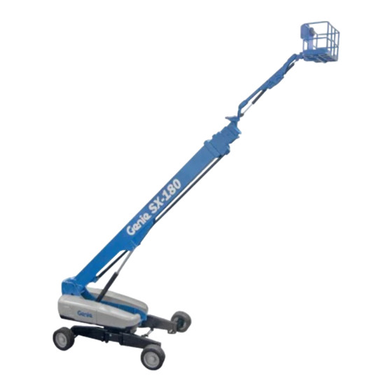
Terex Genie SX-180 Operator's Manual
Hide thumbs
Also See for Genie SX-180:
- Service and repair manual (298 pages) ,
- Maintenance manual (198 pages) ,
- Operator's manual (85 pages)

Related Manuals for Terex Genie SX-180


Summary of Contents for Terex Genie SX-180
- Page 1 Operator's Manual SX-180 from SX18015-220 to SX18015-292 with Maintenance Information Original Instructions Second Edition First Printing Part No. 1258939...
-
Page 2: Table Of Contents
Specifications ............62 Copyright © 2014 by Terex Corporation Second Edition: First Printing, September 2014 Genie is a registered trademark of Terex South Dakota, Inc. in the U.S.A. and many other countries. Complies with EC Directive 2006/42/EC See EC Declaration of Conformity SX-180 Part No. -
Page 3: Introduction
Second Edition • First Printing Operator's Manual Introduction Introduction About this manual Intended Use Genie appreciates your choice of our machine for This machine is intended to be used only to lift your application. Our number one priority is user personnel, along with their tools and materials to safety, which is best achieved by our joint efforts. - Page 4 Operator's Manual Second Edition • First Printing Introduction Contacting the Manufacturer At times it may be necessary to contact Genie. When you do, be ready to supply the model number and serial number of your machine, along with your name and contact information. At minimum, Genie should be contacted for: Danger Accident reporting...
- Page 5 Second Edition • First Printing Operator's Manual Introduction Safety Sign Maintenance Hazard Classification Replace any missing or damaged safety signs. Decals on this machine use symbols, color coding Keep operator safety in mind at all times. Use mild and signal words to identify the following: soap and water to clean safety signs.
-
Page 6: Symbol And Hazard Pictorials Definitions
Operator's Manual Second Edition • First Printing Symbol and Hazard Pictorials Definitions Symbol and Hazard Pictorials Definitions Crushing hazard Keep away from Crush hazard Overhead obstruction Collision hazard moving parts Electrocution hazard Maintain required Tip-over hazard Tip-over hazard Tip-over hazard clearance Electrocution hazard Avoid contact... - Page 7 Second Edition • First Printing Operator's Manual Symbol and Hazard Pictorials Definitions Platform tie-down Lifting & tie down instructions Tie-down point Lifting point instructions Wind speed Maximum capacity Weight of welder Wheel load Tire specifications reduces capacity Recovery procedure if tilt alarm sounds while elevated.
-
Page 8: General Safety
Operator's Manual Second Edition • First Printing General Safety General Safety SX-180 Part No. 1258939... - Page 9 Second Edition • First Printing Operator's Manual General Safety 219958 219958 161688 161691 161688 114258 133067 133067 82487 114248 82487 114248 B 161691 82487 82487 B Part No. 1258939 SX-180...
- Page 10 Operator's Manual Second Edition • First Printing General Safety SX-180 Part No. 1258939...
-
Page 11: Personal Safety
Second Edition • First Printing Operator's Manual Personal Safety Personal Safety Personal Fall Protection Personal fall protection equipment (PFPE) is required when operating this machine. Occupants must wear a safety belt or harness in accordance with governmental regulations. Attach the lanyard to the anchor provided in the platform. Operators must comply with employer, job site and governmental rules regarding the use of personal protective equipment. -
Page 12: Work Area Safety
Operator's Manual Second Edition • First Printing Work Area Safety Work Area Safety Electrocution Hazards Keep away from the machine if it contacts This machine is not electrically insulated and will energized power lines. not provide protection from contact with or Personnel on the ground proximity to electrical current. - Page 13 Second Edition • First Printing Operator's Manual Work Area Safety Do not raise or extend the If the tilt alarm sounds with the boom unless the machine platform uphill: is on a firm, level surface. Lower the boom. Retract the boom. If the tilt alarm sounds with the platform downhill: Retract the boom.
- Page 14 Operator's Manual Second Edition • First Printing Work Area Safety Do not alter or disable machine components that in Use extreme care and any way affect safety and stability. slow speeds while driving the machine in the Do not replace items critical to machine stability stowed position across with items of different weight or specification.
- Page 15 Second Edition • First Printing Operator's Manual Work Area Safety Operation on Slopes Hazards Do not place or attach fixed or overhanging Do not drive the machine on a slope that exceeds loads to any part of this the maximum uphill, downhill or side slope rating of machine.
- Page 16 Operator's Manual Second Edition • First Printing Work Area Safety Fall Hazards Collision Hazards Occupants must wear a Be aware of limited sight safety belt or harness in distance and blind spots accordance with when driving or operating. governmental regulations. Attach the lanyard to the anchor provided in the platform.
- Page 17 Second Edition • First Printing Operator's Manual Work Area Safety Bodily Injury Hazard Observe and use the color-coded direction arrows on the platform controls and drive chassis for drive Always operate the machine in a well-ventilated and steer functions. area to avoid carbon monoxide poisoning. Do not lower the boom Do not operate the machine with a hydraulic oil or unless the area below is...
- Page 18 Operator's Manual Second Edition • First Printing Work Area Safety Damaged Machine Hazards Battery Safety Do not use a damaged or malfunctioning machine. Burn Hazards Conduct a thorough pre-operation inspection of the Batteries contain acid. machine and test all functions before each work Always wear protective shift.
- Page 19 Second Edition • First Printing Operator's Manual Work Area Safety Pipe Cradle Safety Welder Safety Read, understand and obey all warnings and Read, understand and obey all warnings and instructions provided with the pipe cradles. instructions provided with the welding power unit. Do not exceed the rated platform capacity.
-
Page 20: Legend
Operator's Manual Second Edition • First Printing Legend Legend Square-end tire Platform controls Ground controls Sliding mid-rail Boom Manual storage container Jib boom 10 Lanyard anchorage points Platform 11 Foot switch Circle-end tire SX-180 Part No. 1258939... -
Page 21: Controls
Second Edition • First Printing Operator's Manual Controls Controls STOP 230984 A Ground Control Panel LCD readout screen Jib boom up/down buttons 16 High speed function enable button Engine speed select button Boom extend/retract buttons 17 Low speed function enable Red Emergency Stop button 10 20A circuit breaker for system button... - Page 22 Operator's Manual Second Edition • First Printing Controls Ground Control Panel Key switch for off/ground/platform selection Turn the key switch to the off position and the LCD readout screen machine will be off. Turn the key switch to the ground position and the ground controls will operate.
- Page 23 Second Edition • First Printing Operator's Manual Controls 13 Platform rotate left button 19 Turntable rotate right button Press the platform rotate left button and the Press the turntable rotate right button and the platform will rotate left. turntable will rotate right. 14 Jib boom rotate right button 20 Emergency power button Press the jib boom rotate right button and the...
- Page 24 Operator's Manual Second Edition • First Printing Controls Platform Control Panel 12 Jib rotate indicator light Horn button Emergency power switch (operating envelope) Platform not level indicator Glow plug switch with 13 Platform overload indicator light indicator light light Machine on incline indicator 10 Engine start switch with 14 Power indicator light light...
- Page 25 Second Edition • First Printing Operator's Manual Controls 19 Dual axis proportional control 22 Drive speed select switch with 24 Axle extend/retract switch handle for drive and steer indicator lights with indicator lights functions Machine on incline symbol: 25 Drive enable switch with OR Proportional control Low range operation for indicator light...
- Page 26 Operator's Manual Second Edition • First Printing Controls Platform Control Panel Emergency power switch with indicator light Use emergency power if the primary power Horn button source (engine) fails. Press this button and the horn will sound. Push down the foot switch and simultaneously Release the button and the horn will stop.
- Page 27 Second Edition • First Printing Operator's Manual Controls 12 Jib rotate indicator light (operating envelope) 19 Dual axis proportional control handle for drive and steer functions Continued use of the rotate jib right function OR Proportional control handle for drive will cause the jib rotate indicator light to flash.
- Page 28 Operator's Manual Second Edition • First Printing Controls 20 Steer mode select switch with indicator lights 22 Drive select switch with indicator lights Move the steer mode Move the drive select select switch to switch to choose drive choose steer mode. setting.
- Page 29 Second Edition • First Printing Operator's Manual Controls 24 Axle extend/retract switch with indicator lights 26 Dual axis proportional control handle for boom up/down and turntable rotate left/right Move the axle select functions switch to choose an axle setting. The axle extend Move the control handle and retract indicator up and the boom will...
-
Page 30: Inspections
Operator's Manual Second Edition • First Printing Inspections Inspections Pre-operation Inspection Fundamentals It is the responsibility of the operator to perform a pre-operation inspection and routine maintenance. The pre-operation inspection is a visual inspection performed by the operator prior to each work shift. Do Not Operate Unless: The inspection is designed to discover if anything is apparently wrong with a machine before the... - Page 31 Second Edition • First Printing Operator's Manual Inspections Pre-operation Inspection Steer and axle sensors Alarms and beacons (if equipped) Be sure that the operator’s, safety and Nuts, bolts and other fasteners responsibilities manuals are complete, legible and in the storage container located in the ...
- Page 32 Operator's Manual Second Edition • First Printing Inspections Function Test Fundamentals The function tests are designed to discover any malfunctions before the machine is put into service. The operator must follow the step-by-step instructions to test all machine functions. A malfunctioning machine must never be used. If malfunctions are discovered, the machine must be Do Not Operate Unless: tagged and removed from service.
- Page 33 Second Edition • First Printing Operator's Manual Inspections Test the Extendable Axles At the Ground Controls Note: Start this test with the axles retracted. Select a test area that is firm, level and free of obstruction. At the ground controls, press and hold a function enable/speed select button and press Turn the key switch to ground control.
- Page 34 Operator's Manual Second Edition • First Printing Inspections 11 Turn the key switch to platform control. At the Test Machine Functions platform controls, move the drive control 16 Do not press and hold a function enable/speed handle in the forward direction and move the select button.
- Page 35 Second Edition • First Printing Operator's Manual Inspections Test the Tilt Sensor Test the Operating Envelope 22 Press one of the LCD 25 Simultaneously press the 2 screen control buttons until LCD screen control buttons TURNTABLE LEVEL shown to activate status SENSOR X-DIRECTION mode.
- Page 36 Operator's Manual Second Edition • First Printing Inspections Test the Jib Rotate Limit At the Platform Controls 31 At the ground controls, press and hold a Test Emergency Stop function enable button and press either the jib boom rotate right button or the jib boom rotate 35 Turn the key switch to platform control.
- Page 37 Second Edition • First Printing Operator's Manual Inspections Test the Foot Switch Test Machine Functions 40 Push in the platform red Emergency Stop 45 Press down the foot switch. button to the off position. 46 Activate each function control handle, toggle 41 Pull out the red Emergency Stop button to the switch or thumb rocker switch.
- Page 38 Operator's Manual Second Edition • First Printing Inspections 55 Press down the foot switch. Test the Steering 56 Slowly move the control handle in the direction 50 Move the steer indicated by the yellow triangle on the control mode select switch panel OR press the thumb rocker switch in the and choose direction indicated by the yellow triangle.
- Page 39 Second Edition • First Printing Operator's Manual Inspections 61 Slowly move the control handle in the direction Test Drive and Braking indicated by the yellow triangle on the control 66 Press down the foot switch. panel OR press the thumb rocker switch in the direction indicated by the yellow triangle.
- Page 40 Operator's Manual Second Edition • First Printing Inspections Test the Drive Enable System Test Limited Drive Speed 69 Press down the foot switch and lower the 73 Press down the foot switch. boom to the stowed position. 74 Raise the boom to 10° above horizontal. 70 Rotate the turntable until the boom moves past 75 Slowly move the drive control handle to the full 50°.
- Page 41 Second Edition • First Printing Operator's Manual Inspections 90 Press down the foot switch. Test Drive Tilt Cutout 91 With the boom fully stowed, drive the machine 81 Press down the foot switch. onto a slope where the chassis angle is 82 With the boom fully stowed, drive the machine greater than 3°...
- Page 42 Operator's Manual Second Edition • First Printing Inspections Test Emergency Controls 99 Push in the red Emergency Stop button to the off position to shut off the engine. 100 Pull out the red Emergency Stop button to the on position. 101 Press down the foot switch.
- Page 43 Second Edition • First Printing Operator's Manual Inspections Workplace Inspection Checklist Be aware of and avoid the following hazardous situations: drop-offs or holes bumps, floor obstructions or debris sloped surfaces Do Not Operate Unless: unstable or slippery surfaces ...
- Page 44 Operator's Manual Second Edition • First Printing Inspections Inspection for Decals with Part No. Decal Description Symbols 114249 Label – Tip-over Hazard, Tires 114251 Label – Explosion Hazard Use the pictures on the next page to verify that all 114252 Label –...
- Page 45 Second Edition • First Printing Operator's Manual Inspections Part No. 1258939 SX-180...
-
Page 46: Operating Instructions
Operator's Manual Second Edition • First Printing Operating Instructions Operating Instructions Fundamentals The Operating Instructions section provides instructions for each aspect of machine operation. It is the operator’s responsibility to follow all the safety rules and instructions in the operator’s, safety and responsibilities manuals. - Page 47 Second Edition • First Printing Operator's Manual Operating Instructions Starting the Engine Emergency Stop At the ground controls, turn the key switch to Push in the red Emergency Stop button to the off the desired position. position at the ground controls or the platform controls to stop all machine functions and turn the Be sure both ground and platform control red engine off.
- Page 48 Operator's Manual Second Edition • First Printing Operating Instructions To Extend and Retract Axles Operation from Ground Turn the key switch to platform control. Turn the key switch to ground control. Pull out the red Emergency Stop button to the At the platform controls, on position.
- Page 49 Second Edition • First Printing Operator's Manual Operating Instructions To Steer Operation from Platform Press down the foot switch. Turn the key switch to platform control. Select the steer mode by moving the steer Pull out both ground and platform red mode switch.
- Page 50 Operator's Manual Second Edition • First Printing Operating Instructions Driving on a slope To determine the slope grade: Determine the uphill, downhill and side slope Measure the slope with a digital inclinometer OR ratings for the machine and determine the slope use the following procedure.
- Page 51 Second Edition • First Printing Operator's Manual Operating Instructions Drive Enable Engine Idle Select (rpm) Light on indicates that the primary Select the engine idle (rpm) by boom has moved past 50° in pressing the engine idle select either direction, at the square end switch.
- Page 52 Operator's Manual Second Edition • First Printing Operating Instructions Operating Envelope Indicator Lights Out of Operational Envelope Recovery The operating envelope indicator lights will come If all functions stop operating, you may have on to notify the operator that a function has been exceeded the operational envelope.
- Page 53 Second Edition • First Printing Operator's Manual Operating Instructions Generator Machine Not Level Indicator Light To operate the generator, move the generator If the tilt alarm sounds when the toggle switch. platform is raised, the Machine Not Level indicator light will come on Note: If the foot switch is activated during and the drive function in one or generator start-up, the generator will not operate.
- Page 54 Operator's Manual Second Edition • First Printing Operating Instructions Pipe Cradle Instructions Observe and Obey: The pipe cradle assembly consists of 2 pipe Pipe cradles must be installed on the inside of cradles positioned at either side of the platform the platform.
- Page 55 Second Edition • First Printing Operator's Manual Operating Instructions Pipe Cradle Operation Be sure the pipe cradle assembly and installation instructions have been followed properly and that the pipe cradles are secured to the platform railings. Place the load so that it rests in both pipe cradles.
-
Page 56: Transport And Lifting Instructions
Operator's Manual Second Edition • First Printing Transport and Lifting Instructions Transport and Lifting Instructions Be sure the turntable is secured with the turntable rotation lock before transporting. Be sure to unlock the turntable for operation. Do not drive the machine on a slope that exceeds the uphill, downhill or side slope rating. - Page 57 Second Edition • First Printing Operator's Manual Transport and Lifting Instructions Securing the Platform Securing to Truck or Trailer for Transit Note: Be aware of the boom position during the platform stowing sequence to avoid contact with Always use the turntable rotation lock pin each the boom.
- Page 58 Operator's Manual Second Edition • First Printing Transport and Lifting Instructions Fully lower the boom onto the turntable boom As the jib and platform approach the boom, rest pad. Raise the jib if necessary so the rotate the platform toward the boom until it platform does not contact the trailer deck.
- Page 59 Second Edition • First Printing Operator's Manual Transport and Lifting Instructions Securing the Chassis Use chains of ample load capacity. Use a minimum of 6 chains. Adjust the rigging to prevent damage to the chains. Part No. 1258939 SX-180...
- Page 60 Operator's Manual Second Edition • First Printing Transport and Lifting Instructions Lifting Instructions Fully extend the axles. Fully lower and retract the boom. Fully lower the jib. Remove all loose items on the machine. Determine the center of gravity of your machine Observe and Obey: using the table and the picture on this page.
-
Page 61: Maintenance
Second Edition • First Printing Operator's Manual Maintenance Maintenance Check the Engine Oil Level Maintaining the proper engine oil level is essential to good engine performance and service life. Operating the machine with an improper oil level Observe and Obey: can damage engine components. - Page 62 Operator's Manual Second Edition • First Printing Maintenance Check the Hydraulic Oil Level Check the Engine Coolant Level – Liquid Cooled Models Maintaining the hydraulic oil at the proper level is essential to machine operation. Improper hydraulic Maintaining the engine coolant at the proper level oil levels can damage hydraulic components.
- Page 63 Second Edition • First Printing Operator's Manual Maintenance Check the Batteries Scheduled Maintenance Maintenance performed quarterly, annually and every two years must be completed by a person trained and qualified to perform maintenance on Proper battery condition is essential to good this machine according to the procedures found in machine performance and operational safety.
-
Page 64: Specifications
Operator's Manual Second Edition • First Printing Specifications Specifications Model AC outlet in platform SX-180 Tire size 445D50/710, 18 ply HD FF Height, working maximum 56.7 m Weight 24,948 kg Height, platform maximum 54.8 m (Machine weights vary with option configurations. See Height, stowed maximum 3.05 m serial label for specific machine weight.) - Page 65 Second Edition • First Printing Operator's Manual Specifications SX-180 Range of Motion Chart SX-180 Part No. 1258939 Operator's Manual Second Edition • First Printing Part No. 1258939 SX-180...
- Page 66 www.genielift.com...
Need help?
Do you have a question about the Genie SX-180 and is the answer not in the manual?
Questions and answers