Table of Contents
Advertisement
Quick Links
Advertisement
Table of Contents

Related Manuals for National Instruments 9853


Summary of Contents for National Instruments 9853
- Page 1 NI-9853...
- Page 2 GETTING STARTED GUIDE NI 9853 2-Port, High-Speed CAN Module Français Deutsch 日本語 한국어 简体中文 ni.com/manuals This document explains how to connect to the NI 9853.
-
Page 3: Safety Guidelines
The NI 9853 module requires the latest NI 985x software to be ni.com/ installed. The latest version of the NI 985x software is at downloads. Before you begin, complete the software and Note hardware installation procedures in your chassis documentation. -
Page 4: Safety Guidelines For Hazardous Locations
Safety Guidelines for Hazardous Locations The NI 9853 is suitable for use in Class I, Division 2, Groups A, B, C, D, T4 hazardous locations; Class I, Zone 2, AEx nA IIC T4 and Ex nA IIC T4 hazardous locations; and nonhazardous locations only. -
Page 5: Special Conditions For Hazardous Locations Use In Europe And Internationally
Special Conditions for Hazardous Locations Use in Europe and Internationally The NI 9853 has been evaluated as Ex nA IIC T4 Gc equipment under DEMKO Certificate No. 03 ATEX 0324020X and is IECEx 14.0089X certified. Each NI 9853 is marked... -
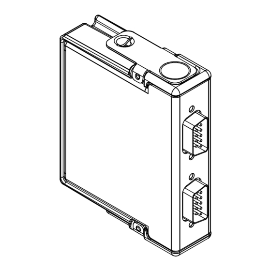
Page 6: Wiring The Ni 9853
Wiring the NI 9853 The NI 9853 has two 9-pin male D-Sub connectors that provide connections to a CAN bus. Each port on the NI 9853 has pins for CAN_H and CAN_L, to which you connect the CAN bus signals. - Page 7 CAN bus without being damaged. Pinouts for CAN0 and CAN1 of the NI 9853 are listed in Tables 1 and 2. Table 4 lists recommended termination resistor values.
- Page 8 Table 1. Pin Assignments for CAN0 Connector Signal No Connection (NC) CAN_L SHLD CAN_H NI 9853 Getting Started Guide | © National Instruments | 7...
-
Page 9: Can Bus Topology And Termination
SHLD CAN_H CAN Bus Topology and Termination A CAN bus consists of two or more CAN nodes cabled together. The CAN_H and CAN_L pins of each node are connected to the 8 | ni.com | NI 9853 Getting Started Guide... - Page 10 Figure 1 shows a simplified diagram of a CAN bus with multiple CAN nodes and proper termination resistor (R ) locations. NI 9853 Getting Started Guide | © National Instruments | 9...
-
Page 11: Connecting A Can Bus To The Ni 9853
Node Connecting a CAN Bus to the NI 9853 You can connect each port of the NI 9853 to any location on a CAN bus. Figure 2 shows one example of connecting CAN0 of the NI 9853 directly to one CAN node, and CAN1 directly to... - Page 12 CAN node. CAN1 requires an external power supply on the CAN bus. Figure 2. Connecting Both Ports of the NI 9853 to CAN Buses (SHLD) (SHLD) CAN_H CAN_H Cable CAN0 (With CAN_L CAN_L Optional Shield) NI 9853 (SHLD) (SHLD)
- Page 13 Table 3. ISO 11898 Specifications for Characteristics of a CAN_H and CAN_L Pair of Wires Characteristic Value Impedance 95 Ω min, 120 Ω nominal, 140 Ω max Length-related resistance 70 mΩ/m nominal Specific line delay 5 ns/m nominal 12 | ni.com | NI 9853 Getting Started Guide...
-
Page 14: Termination Resistors
ISO 11898, CiA DS 102, and DeviceNet specifications. ISO 11898 specifies 40 m total cable length with a maximum stub length of 0.3 m for a bit rate of 1 Mb/s. The ISO 11898 NI 9853 Getting Started Guide | © National Instruments | 13... -
Page 15: Number Of Can Nodes
The NI 9853 has two full-featured, independent CAN ports that are isolated from each other, and from the other modules in the system. Each port or the NI 9853 has a Philips SJA1000 controller that is CAN 2.0B-compatible and fully supports both 11-bit and 29-bit identifiers. - Page 16 ISO 11898 standard and supports baud rates up to 1 Mbps. Figure 3. NI 9853 Hardware Overview +5 V +5 V_ISO Iso Pwr CAN_H CAN_L Transceiver Controller CAN0 Ext Pwr +5 V Supply CAN_H CAN_L Transceiver Controller CAN1 NI 9853 Getting Started Guide | © National Instruments | 15...
-
Page 17: High-Speed Can Characteristics
Supply voltage range (V ........... CAN1 +9 to +30 VDC ........... CAN0 ............MTBF 1,816,913 hours at 25 °C; Bellcore Issue 6, Method 1, Case 3, Limited Part Stress Method 16 | ni.com | NI 9853 Getting Started Guide... -
Page 18: Power Requirements
Active mode 1 W max ........... Sleep mode 250 mW max Physical Characteristics To clean the module, wipe it with a dry towel............Weight Approx. 144 g (5.0 oz) NI 9853 Getting Started Guide | © National Instruments | 17... - Page 19 , verified by a 5 s dielectric withstand test The maximum voltage that can be applied or output between any port or V terminal and a COM terminal without creating a safety hazard. 18 | ni.com | NI 9853 Getting Started Guide...
- Page 20 Such voltage measurements include signal levels, special equipment, limited-energy parts of equipment, circuits powered by regulated low-voltage sources, and electronics. Do not connect the NI 9853 to signals or use for Note measurements within Measurement Categories II, III, or IV.
-
Page 21: Hazardous Locations
UL 61010-1, CSA 61010-1 • EN 60079-0:2012, EN 60079-15:2010 • IEC 60079-0: Ed 6, IEC 60079-15; Ed 4 • UL 60079-0; Ed 5, UL 60079-15; Ed 3 • CSA 60079-0:2011, CSA 60079-15:2012 20 | ni.com | NI 9853 Getting Started Guide... -
Page 22: Electromagnetic Compatibility
In Europe, Canada, Australia and New Zealand (per CISPR 11) Class A equipment is intended for use only in heavy- industrial locations. NI 9853 Getting Started Guide | © National Instruments | 21... -
Page 23: Online Product Certification
94/9/EC; Potentially Explosive Atmospheres (ATEX) Online Product Certification Refer to the product Declaration of Conformity (DoC) for additional regulatory compliance information. To obtain product ni.com/ certifications and the DoC for this product, visit 22 | ni.com | NI 9853 Getting Started Guide... -
Page 24: Shock And Vibration
5 g, 10 Hz to 500 Hz 60068-2-6) ............Operating shock (IEC 30 g, 11 ms half sine; 50 g, 60068-2-27) 3 ms half sine; 18 shocks at 6 orientations NI 9853 Getting Started Guide | © National Instruments | 23... - Page 25 Operating humidity 10% RH to 90% RH, (IEC 60068-2-78) noncondensing ............Storage humidity 5% RH to 95% RH, (IEC 60068-2-78) noncondensing ............Pollution Degree ............Maximum altitude 5,000 m Indoor use only. 24 | ni.com | NI 9853 Getting Started Guide...
-
Page 26: Environmental Management
EU Customers NI products must be disposed of according to local laws and regulations. For more information about how ni.com/ to recycle NI products in your region, visit environment/weee. NI 9853 Getting Started Guide | © National Instruments | 25... -
Page 27: Worldwide Support And Services
At ni.com/support, you have access to everything from troubleshooting and application development self-help resources to email and phone assistance from NI Application Engineers. Visit ni.com/services for NI Factory Installation Services, repairs, extended warranty, and other services. 26 | ni.com | NI 9853 Getting Started Guide... - Page 28 For telephone support outside the United States, visit the Worldwide Offices section of ni.com/niglobal to access the branch office websites, which provide up-to-date contact information, support phone numbers, email addresses, and current events. NI 9853 Getting Started Guide | © National Instruments | 27...
- Page 29 Refer to the NI Trademarks and Logo Guidelines at for information on National Instruments trademarks. Other product and company names mentioned herein are trademarks or trade names of their respective companies. For patents covering National Instruments products/technology, refer to the appropriate location: Help»Patents in your software, patents.txt...
Need help?
Do you have a question about the 9853 and is the answer not in the manual?
Questions and answers