Table of Contents
Advertisement
Quick Links
X7502236300
01/14
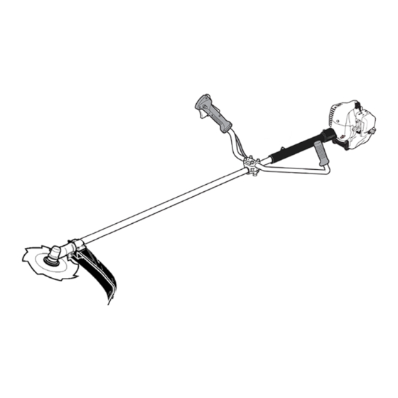
SHINDAIWA GRASS TRIMMER TO BRUSHCUTTER
CONVERSION KIT FOR T242 GRASS TRIMMER
MODEL: BCK-10B
WARNING!
Minimize the risk of injury to yourself and others! Read the Owner's/Opera-
tor's manual originally supplied with the unit that is being upgraded and
familiarize yourself with the contents. Always wear eye and hearing protec-
tion when operating your unit.
Advertisement
Table of Contents

Related Manuals for Shindaiwa BCK-10B


Summary of Contents for Shindaiwa BCK-10B
- Page 1 SHINDAIWA GRASS TRIMMER TO BRUSHCUTTER CONVERSION KIT FOR T242 GRASS TRIMMER MODEL: BCK-10B WARNING! Minimize the risk of injury to yourself and others! Read the Owner's/Opera- tor's manual originally supplied with the unit that is being upgraded and familiarize yourself with the contents. Always wear eye and hearing protec- tion when operating your unit.
-
Page 2: Table Of Contents
The instructions described in this manual are intended to help you unit is equipped with a Shindaiwa-approved get the most from your Shindaiwa power tool as well as to protect handlebar or barrier. you and others from harm. These procedures are guidelines for... -
Page 3: Safety Labels
A new label is provided in this kit and additional labels are available from your local authorized Shindaiwa dealer. Pri- or to installing the new label, Remove old label and clean the outer tube with rubbing alcohol or similar cleaner. -
Page 4: Kit Contents
Blade Thrust ‘Blade thrust’ is a sudden sideways or backward motion of the brushcutter. Such motion may occur when the blade jams or catches on an object such as a sapling tree or tree stump. BE CONSTANTLY ALERT FOR BLADE THRUST AND GUARD AGAINST ITS EFFECTS! Eleven O’Clock Handle Bar... -
Page 5: Assembly
Assembly Removing the Existing Cutting Attachment Shield 1. Remove the four socket-head cap screws (NN), upper clamp (OO), and two shims (PP). 2. Remove the cutting attachment shield from the gearcase. Remove Handle Assembly T242 with 1-screw Handle 1. Remove handle assembly. Retain all parts for future use. -
Page 6: Remove Power Head
Disconnect Throttle Cable-Ignition Wires 1. Loosen air cleaner cover knob and remove air cleaner cover. 2. Remove wire end of throttle linkage cable (TT) from carburetor throttle swivel hole. 3. Disconnect two ignition stop switch leads: a. Disconnect wire with ring terminal from grounding screw (XX) on engine. -
Page 7: Install Handlebar Bracket And Disconnect Throttle Cable-Ignition Handlebar
Install Handlebar Bracket and Handlebar 1. Install lower handlebar cap (B) and handle bar mounting bracket (E) on outer drive shaft tube (B1) using two 5x25 mm socket head cap screws (C). Do not tighten screws securely until final adjustments are completed. 2. -
Page 8: Install Debris Shield
Install Debris Shield Assemble the Cutting Attachment Shield to the Outer Tube. 1. Insert the cutting attachment shield (O) between the outer tube and the cutting attachment mounting plate (H1). 2. Fit the two shims (G) and the upper clamp (F) over the outer tube and install the four socket-head cap screws (H) finger tight. -
Page 9: Install Bruschcutter Blade
Install Brushcutter Blade NOTE: There are four gear case configurations. Select one of the following instruc- tions to properly install a metal blade. Gear Case #1 with notched flange: 1. Turn the unit over so that the gearcase output shaft faces UP. 2. - Page 10 Install Brushcutter Blade Gear Case #2 with side-mounted locking tool hole: 1. Turn the unit over so that the gearcase output shaft faces UP. 2. Align the notch in trimmer head holder (HH) with the notch in the gear case flange.
- Page 11 Install Brushcutter Blade Gear Case #3 with side-mounted locking tool hole and grooved output shaft: 1. Turn the unit over so that the gearcase output shaft faces UP. 2. Align the notch in trimmer head holder (HH) with the notch in the gear case flange.
- Page 12 Install Brushcutter Blade Gear Case #4 with side-mounted locking tool hole, grooved output shaft, and gear case cover: 1. Turn the unit over so that the gear case output shaft faces UP. 2. Lock gear case by inserting a 4mm hex wrench (LL) into locking hole. Ap- ply light pushing force to wrench while turning splined power output shaft.
-
Page 13: Balance And Adjust Unit
Balance and Adjust Unit 1. Loosen harness clamp screw. 2. Put on harness and attach unit to harness. 3. Slide harness clamp (L) up or down until unit balances with head approxi- mately 50-75 mm (2 -3 in.) from the ground. 4. -
Page 14: Notes
NOTES... - Page 15 NOTES...
- Page 16 If you require assistance or have questions concerning the application, operation or maintenance of this product you may call the Shindaiwa Consumer Product Support Department at 1-877-986-7783 from 8:30 am to 4:30 pm (Central Standard Time) Monday through Friday. Before calling, please know the model and serial number of your unit.
Need help?
Do you have a question about the BCK-10B and is the answer not in the manual?
Questions and answers