Table of Contents
Advertisement
Quick Links
IMPORTANT! Read entire instruction sheet before you start installation and assembly.
Installation and Assembly:
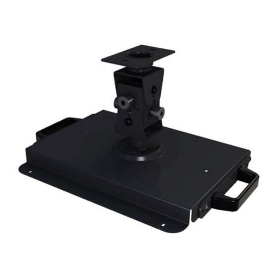
Projector Adapter Plate
Model: NP750CM
• Installer must verify that the ceiling will safely
support four times the combined weight of all
attached equipment and hardware.
WARNING
Installation and Assembly:
Adapter Plate for NEC Projector
Model PX-750U
• It is the responsibility of the installer to ensure
that the projector is properly ventilated. Spacers
are provided to raise the mount off the projector
surface.
1 of 8
Model:
Max Load Capacity:
60 lb (22.3 kg)
CAUTION
ISSUED: 09-15-11 SHEET #:125-9244-1
PX750CM
Advertisement
Table of Contents

Related Manuals for NEC PX750CM


Summary of Contents for NEC PX750CM
- Page 1 IMPORTANT! Read entire instruction sheet before you start installation and assembly. Installation and Assembly: Projector Adapter Plate Model: NP750CM WARNING • Installer must verify that the ceiling will safely support four times the combined weight of all attached equipment and hardware. Installation and Assembly: Adapter Plate for NEC Projector Model PX-750U CAUTION • It is the responsibility of the installer to ensure that the projector is properly ventilated. Spacers are provided to raise the mount off the projector surface. 1 of 8 PX750CM...
-
Page 2: Parts List
NOTE: Read entire instruction sheet before you start installation and assembly. Parts List Description A adapter assembly B M4 x 12 mm socket pin serrated washer head screw C M5 x 10 mm socket pin serrated washer head screw D M4 x 40 mm socket pin serrated washer head screw E 4 mm allen wrench F .375 spacer G .75 spacer H projector mount assembly I column connector J ceiling plate K .25" x .5" x .25" spacer L #10-32 x 3/8" thumb screw M #10-32 x 3/8" socket pin serrated washer head screw N 10-32 x 3/8" slotted set screw O concrete anchor P #10-32 x 3/8" socket pin screw Q #14 x 2.5" wood screw R 5 mm allen wrench S M5 x 10 mm type-F screw Before you start make sure all parts listed are included with your product. - Page 3 Installation To Wood Joist Finished Ceilings, Exposed Wood Joists, or Wood Beam Ceilings Drill two 5/32" (4 mm) dia. holes to a minimum depth of 2.5" (64 mm). Attach ceiling plate (J) to ceiling with two #14 x 2.5" wood screws (Q) using 3/8" (10 mm) socket wrench as shown in figure 1.1. NOTE: For optional cord management, install two spacers (K) between ceiling plate (J) and ceiling as shown in figure 1.2. Skip to step 2 for flush mount installation. Skip to step 3 for extension column installation. WARNING • Tighten wood screws so that ceiling plate is firmly attached, but do not overtighten. Overtightening can damage the screws, greatly reducing their holding power.
- Page 4 Installation to Concrete Ceilings • Concrete must be 2000 psi density minimum. Lighter density concrete may not hold concrete anchor. • Installer must verify that the supporting surface will safely support the combined load of the equipment and all at- tached hardware and components. Drill two 5/16" (8 mm) dia. holes to a minimum depth of 2.5" (64 mm). Insert anchors (O) in holes flush with wall. Place ceiling plate (J) over anchors and secure using two #14 x 2.5" screws (Q). IMPORTANT: It is the responsibility of the installer to verify that the ceiling will safely support the combined load of all attached hardware and components. Skip to step 2 for flush mount installation. Skip to step 3 for extension column installation. WARNING • Tighten wood screws firmly, but do not overtighten. Overtightening can damage the screws, greatly reducing their holding power. • Never tighten in excess of 80 in • lb (9 N.M.). • Always attach concrete expansion anchors directly to load-bearing concrete.
- Page 5 Flush Mount Installation Hand thread projector mount assembly (H) into ceiling plate (J) as shown in figure 2.1. Align the notch of projector mount assembly with one of the four holes in ceiling plate (J) and secure with an M5 x 10 mm socket pin screw (S) as shown in detail 1. NOTE: Slotted set screw (N) is used to jam against the threads of the projector mount assembly to prevent any excess movement of the projector mount assembly (H). Do not overtighten screw; overtightening screw will damage threads making it difficult to separate projector mount assembly from ceiling plate. NOTCH DETAIL 1 fig. 2.1 5 of 8 ISSUED: 09-15-11 SHEET #:125-9244-1...
- Page 6 Extension Column Installation Hand thread extension column into ceiling place (J). Align notch of extension column with one of the four holes in ceiling plate (J) and secure with an M5 x 10 mm socket pin screw (S) using allen wrench (E) as shown in detail 2. Hand thread column connector (I) onto extension column. Align slot in extension column with one of the top holes of the column connector (I). Insert and tighten one #10-32 x 3/8" socket pin screw (P) through column connector (I) into slot of extension column using 4 mm security allen wrench (O) as shown in detail 3. Hand thread projector mount assembly (H) into column connector (I). Align slot of projector mount assembly (H) with one of the bottom holes in column connector (I). Insert and tighten one #10-32 x 3/8" socket pin screw (P) through column connector into projector mount assembly using 4 mm security allen wrench (E) as shown in detail 4. NOTE: Slotted set screws (N) are used to jam against the threads of each connecting joint to prevent any excess movement. Do not overtighten screw. Overtightening screw will damage threads making it difficult to separate components. EXTENSION COLUMN (SOLD SEPARATELY) (UL LISTED EXT OR ADJ SERIES) fig. 3.1 6 of 8 ISSUED: 09-15-11 SHEET #:125-9244-1 DETAIL 2 DETAIL 3 DETAIL 4...
- Page 7 Fasten adapter assembly (A) to bottom of projector using two M4 x 40 mm socket pin serrated washer head screws (D) with spacers (F and G), and four M4 x 12 mm socket pin serrated washer head screws (B) in orientation as shown below. FRONT OF PROJECTOR M4 X 40 MM SOCKET PIN SERRATED WASHER HEAD SCREW (D), WITH SPACERS (F AND G) M4 X 12 MM SOCKET PIN SERRATED WASHER HEAD SCREW (B) Handles can be pulled out for additional leverage as shown below. HANDLE FRONT OF PROJECTOR FRONT OF PROJECTOR Handles can be secured to adapter assembly (A) using four M5 x 10 mm socket pin serrated washer head screws (C) as shown below. FRONT OF PROJECTOR 7 of 8 ISSUED: 09-15-11 SHEET #:125-9244-1...
- Page 8 Attaching Adapter Plate to Projector Mount Attach projector to projector mount assembly (H) by inserting the mount into the adapter plate and twisting until the adapter plate will no longer turn. The spring loaded captive screw should line up with a corresponding hole on the adapter plate. Push down and tighten the spring loaded captive screw to secure the adapter plate to the mount. If not using the optional security feature, fasten thumb screw (L) in the hole opposite the spring loaded captive screw. OPTIONAL: For Armor Lock™ security, insert #10-32 x 3/8" serrated washer head screw (M) in the hole opposite the spring loaded captive screw. Tighten with 4 mm security allen wrench (E). This will prevent the projector from being removed. CAPTIVE SCREW PROJECTOR PITCH ADJUSTMENT KNOB 8 of 8 All other brand and product names are trademarks or registered trademarks of their respective owners. Use knobs to adjust projector mount roll and pitch. Knobs also may be adjusted using allen wrenches (E,R). Tighten socket pin screw using allen wrench (E) to lock roll and pitch position. SOCKET PIN SCREW ISSUED: 09-15-11 SHEET #:125-9244-1 © 2011, Peerless Industries, Inc. All rights reserved.
Need help?
Do you have a question about the PX750CM and is the answer not in the manual?
Questions and answers