Sign In
Upload
Download
Table of Contents
Contents
Add to my manuals
Delete from my manuals
Share
URL of this page:
HTML Link:
Bookmark this page
Add
Manual will be automatically added to "My Manuals"
Print this page
×
Bookmark added
×
Added to my manuals
Manuals
Brands
Electrolux Manuals
Washer
WB6-90
Installation manual
Electrolux WB6-90 Installation Manual
Washer-extractors
Hide thumbs
1
2
Table Of Contents
3
4
5
6
7
8
9
10
11
12
13
14
15
16
17
18
19
20
21
22
23
24
25
26
27
28
29
30
31
32
33
34
35
36
37
38
39
40
41
42
43
44
45
46
47
48
49
50
51
52
53
54
55
56
57
58
59
60
61
62
63
64
65
66
67
68
69
70
71
72
page
of
72
Go
/
72
Contents
Table of Contents
Bookmarks
Table of Contents
Table of Contents
Safety Precautions
Symbols
Personal Protection Equipment
Preliminary Instructions
Data Plate Explanation
Warranty Terms and Exclusions
Environmental Information
Locking and Tagging Procedure
Handling
Lifting with a Fork-Lift Truck
Lifting with Handlings Straps
Packing-Weight
Packing
Weight
Technical Characteristics
Explanation of Following Installation Drawings
Washer Extractor Type WB6 70
Connections WB6 70
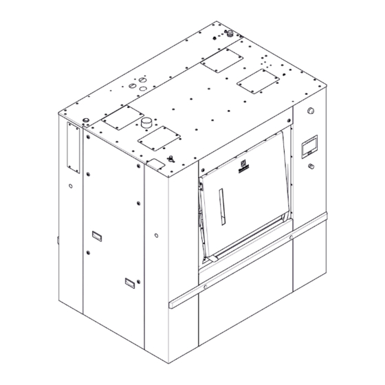
Washer Extractor Type WB6 90
Connections WB6 90
Washer Extractor Type WB6 110
Connections WB6 110
Sound Levels
Working Place Lighting
Supplies
Barrier Partition
Mechanical Installation
Unpacking
Installation
Installing the Shock Absorber Runners
Instructions for Securing the Machine on the Ground
Setting the Bolsters
Remove of the Transport Locks Fitted
Drain Connection
Waters Connections
Liquid Detergents Connection
Connection Scheme of Liquid Detergents
Electrical Liquid Detergents' Connection
Steam Connection
Air Vent Connection
Note about the A.C. Power
Feeder Cable Sections
Electricity Power Supply
Compressed Air Connection
Function Checks
Explanation of Washing Symbols
Washing
Bleaching
Drying
Ironing
Dry or Water Cleaning
Conversion of Measurement Units
Advertisement
Quick Links
Download this manual
Installation manual
Washer-extractors
WB6 70- WB6 90 – WB6 110
01201217/EN
original instructions
Table of
Contents
Previous
Page
Next
Page
1
2
3
4
5
Advertisement
Table of Contents
Need help?
Do you have a question about the WB6-90 and is the answer not in the manual?
Ask a question
Questions and answers
Related Manuals for Electrolux WB6-90
Washer Electrolux WB6-20 User Manual
(50 pages)
Washer Electrolux WB6-27 User Manual
(50 pages)
Washer Electrolux WB6-35 User Manual
(50 pages)
Washer Electrolux WB6-70 Installation Manual
Washer-extractors (72 pages)
Washer Electrolux WB6 110 Installation Manual
Washer-extractors (72 pages)
Washer Electrolux WB6-50 User Manual
(36 pages)
Washer Electrolux W465H Service Manual
Compass control (122 pages)
Washer Electrolux W455H Operating Manual
Type w.55.h compass control (28 pages)
Washer Electrolux Washer Service Manual
Washing machines & washer-dryers with ewm2000evo electronic control (65 pages)
Washer Electrolux Washer User Manual
(18 pages)
Washer Electrolux W365H Service Manual
Clarus control (240 pages)
Washer Electrolux W4400H Service Manual
Clarus control (186 pages)
Washer Electrolux washing machine Service Manual
Diagnostics guide to ewm2000 electronic control washing machines & washer dryers (75 pages)
Washer Electrolux Washing machine User Manual
Electrolux washing machine (26 pages)
Washer Electrolux washing machine Service Manual
Washing machines with ewm 1000 plus electronic control system and “full smd” display board with sensor (49 pages)
Washer Electrolux Washing machine Service Manual
Washing machines with ewm 1000 plus electronic control system and “delta 3” display board (59 pages)
This manual is also suitable for:
Wb6-70
Wb6 110
Table of Contents
Print
Rename the bookmark
Delete bookmark?
Delete from my manuals?
Login
Sign In
OR
Sign in with Facebook
Sign in with Google
Upload manual
Upload from disk
Upload from URL


Need help?
Do you have a question about the WB6-90 and is the answer not in the manual?
Questions and answers