AKO -16524A User Manual
Advanced temperature controller for cold rooms
Hide thumbs
Also See for AKO-16524A:
- Quick manual (57 pages) ,
- User manual (40 pages) ,
- Quick manual (53 pages)

Related Manuals for AKO AKO-16524A


Summary of Contents for AKO AKO-16524A
- Page 1 1652H4A02 Ed.09 AKO-16524A AKO-16525A Advanced temperature controller for cold rooms User manual...
-
Page 2: Table Of Contents
Only qualified personnel should install or perform technical assistance on this product. This product is designed to be used in the applications described in the product manual. AKO Electromecánica gives no guarantee of its operation in any use not foreseen in the manual, and is not responsible for any damage resulting from improper use, configuration, installation or commissioning. -
Page 3: Presentation
-From -40 ºC to +20 °C, if the NTC probe is extended to 1000 m with at least a 0.5 mm cable, the maximum deviation will be 0.25 ºC (cable for probe extension ref. AKO-15586. Earth the cable mesh at one end only). -
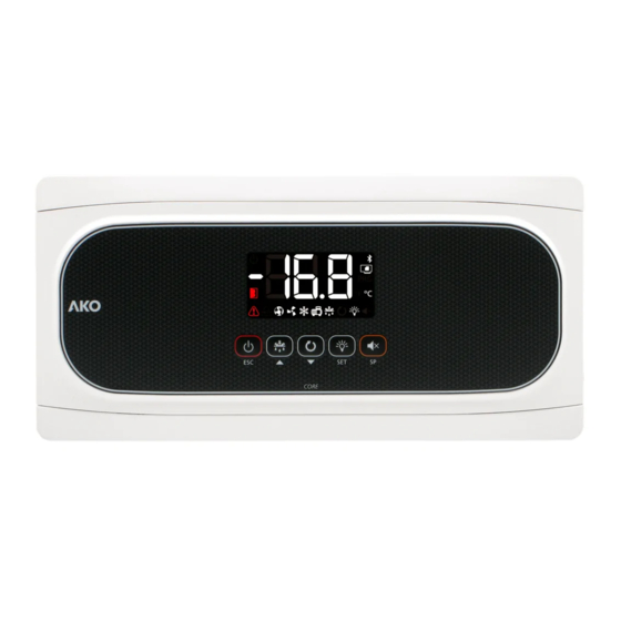
Page 4: Description
1652H4A02 Ed.09 Description Display Keypad Indicators Constant: Stand-By Mode activated. Constant: The cold solenoid is active. Regulation is paused. Flashing: The solenoid should be active but a delay or protection is preventing this. Flashing: Controlled stop process for the regulation in progress. Constant: Compressor active. - Page 5 1652H4A02 Ed.09 Keypad Pressing it for 3 seconds activates/deactivates the Stand-By mode. In this mode, regulation is paused and the m icon is displayed. In the programming menu, it exits the parameter without saving changes, returns to the previous level or exits programming.
-
Page 6: Installation
1652H4A02 Ed.09 Installation Ø Max. 20 mm -Remove the bezels (1) -Make a 1/4 turn of the screws (2) anti-clockwise and open the door (3). -Install the necessary glands (4 / 5) by drilling holes in the Ø Max. 25 mm points indicated on the box. -
Page 7: Wiring
Check the available options on the diagram sheet included with your device. The AKO-16523D model has a contactor which allows for the connection of three-phase defrost resistors, a three- phase compressor or three-phase fans, according to your installation’s requirements. Check how to connect it on the diagram sheet included with your device. -
Page 8: Installation Of The Probes
1652H4A02 Ed.09 Installation of the probes To achieve maximum performance from the advanced controller, the correct installation of the probes is key, as they are responsible for calculating the evaporator’s thermal transfer coefficient, evaluating the start and end of the defrosts and diagnosing problems in the evaporator. -
Page 9: Installation Of The Camm Ako-58500 Module Included
Installation of the CAMM AKO-58500 module included Insert the CAM AKO-58500 module in the pre-installed base as shown in the picture. In combination with the application for AKO CAM Tool mobile devices, the CAM module provides the device with multiple functions: - Data logging... -
Page 10: Initial Configuration (Wizard)
If the regulation cannot be instantly stopped due to its configuration, a controlled stop process starts and the m icon flashes. To stop the controlled stop process and force the step to Stand-by, press the Stand-by key again for 3 seconds. * o00=2 in AKO-16523 / 16520, o00=0 in AKO-16523P / 16520P / 16523D. -
Page 11: Operation
1652H4A02 Ed.09 Operation MESSAGES Pump down malfunction error (stop), the time configured in parameter C20 has been exceeded (see p. 17). Only displayed on screen. Pump down malfunction error (start-up), the time configured in parameter C19 has been exceeded (see p. 17). Only displayed on screen. - Page 12 1652H4A02 Ed.09 MESSAGES Calibration ongoing, therefore, avoid, as far as possible, opening the cold room during the process. For further information, see page 13. Flashing with temperature: Configuration has been changed from 1 to 2 evaporators or vice versa. SELFDRIVE MODE ALERT MESSAGES (Only shown pressing the Q key) Defrost end error in 1/2 evaporator during the calibration, defrost has not ended due to temperature.
-
Page 13: Selfdrive Mode
1652H4A02 Ed.09 SELFDRIVE mode SELFDRIVE modeIf the SELFDRIVE mode is activated (default configuration), the device periodically evaluates the evaporator’s heat transfer, managing the available resources to maximise it. The defrosts are minimised, adapting to the changing conditions of the cold room, reducing heat input into the refrigerated space, thermal stress in the evaporator and energy consumption. -
Page 14: Cold Regulation
1652H4A02 Ed.09 Cold regulation Solenoid control (COOL Relay) SP+C1 Cold production is regulated by means of opening / closing the solenoid valve. When the temperature in probe S1 reaches the set point (SP) value plus the probe's differential (C1), the solenoid opens and causes the temperature to drop. - Page 15 1652H4A02 Ed.09 Regulation of cold with two temperature probes (S1 + S3) This requires configuration of digital input 2 as cold room temperature (I20=10). The device regulates the temperature of the cold room taking into account the reading of both probes. Using parameter C25, the influence of probe S3 is determined in the regulation.
- Page 16 Ÿ By means of the AKONet application. This requires the device to be connected to a Modbus network (see p. 36). Ÿ By means of the CAMM module and the AKO CAMM tool application. EXAMPLE: Configuration (SP+C12)+C1...
- Page 17 1652H4A02 Ed.09 Pump down function This function foresees problems in the compressor caused by movements of coolant, using a stop/start technique for the installation, controlled via the liquid solenoid, the low pressure switch and the compressor itself. This function is only available for In{ options 2, 5 and 7 and requires the connection of a low pressure switch in digital input 1.
-
Page 18: Door Management
1652H4A02 Ed.09 Door management Door management requires configuring one of the digital inputs as “Door contact” (I10 ó I20=1). Standard operating mode (CE=0) Door management allows for the installation's behaviour to be controlled, should the cold room door open through parameters C22 and C23. Parameter C22 defines whether cold production should be stopped if the door opens. -
Page 19: Defrost
1652H4A02 Ed.09 Defrost Types of defrost There are 3 possible defrost types, depending on the option selected in the wizard (Inl): Electric (InI=1, 2 and 3) (d7=0) Defrost is performed through electrical resistors, supplying the evaporator with heat. The operation of fans in this mode depends on parameter F3;... - Page 20 1652H4A02 Ed.09 Control of defrost in standard mode (CE=0) Máx. d1 COLD REGULATION DRIP TIME DEFROST COLD REGULATION FAN START-UP DEFROST DELAY "DEF” MESSAGE SP+C1 Defrost start Defrost will start if: -The time programmed in parameter d0 has elapsed since the start of the last defrost. -We press the H key for 3 seconds.
- Page 21 1652H4A02 Ed.09 Control of defrost in SELFDRIVE mode (CE=1) Defrosts in SELFDRIVE mode are not programmed, but rather the device evaluates the operation of the cold room and manages defrosts depending on the needs of the installation. If a drop in the performance of the cold room is detected due to formation of ice in the evaporator, defrost is activated and it is supervised until its completion.
- Page 22 1652H4A02 Ed.09 Other defrost parameters (They affect in standard and SELFDRIVE mode) Drip time This is established through parameter d9 and sets the time added at the end of defrost to allow for the removal of surplus water from melted evaporator ice, during which there is no cold regulation. Fan start-up delay This is established through parameter F4 and allows for the possible drops left in the evaporator to freeze before the fans activate, preventing them from being projected into the cold room.
- Page 23 1652H4A02 Ed.09 Defrost of a second evaporator This function allows for defrost to be controlled in a second evaporator, provided that defrost is by electric heat, by air or is static. The same type of defrost should be used for the first and second evaporators. This requires configuration of input 2 as a 2nd evaporator probe (l20=8).
-
Page 24: Evaporator Fans
1652H4A02 Ed.09 Evaporator fans Control of fans in standard mode (CE=0) Fans are controlled through probe 2 (evaporator) and parameters F0 (stop temperature) and F1 (probe differential). If probe 2 is not connected or an error in the probe (E2) is detected, the fans continuously operate without taking into account parameters F0 and F1, but taking the remaining parameters (F2 to F4) into account. -
Page 25: Alarms
1652H4A02 Ed.09 Alarms The device warns the user through an on-screen message, activation of a relay (only if o10=1) and a sound alarm when the criteria programmed in the parameters are met. Maximum / minimum temperature alarm It shows the message “AK” or “AL” when the temperature in probe 1 reaches the value configured in parameters A1 (maximum temperature) and A2 (minimum temperature). - Page 26 1652H4A02 Ed.09 Open door alarm The door has been open for a longer time than defined in parameter A12, the open door alarm is activated. In order to detect the open door, configuration is required of one of the digital inputs as “door contact”...
-
Page 27: Alerts
1652H4A02 Ed.09 Alerts The device alerts the user through an on-screen message when an event occurs which requires his/her attention. However, it does not activate the sound alarm or the alarm relay (if active). Defrost finished by time alarm The message Adt is displayed when a defrost has completed due to time-out, if parameter A8=1. Pump down malfunction error (stop) The message Pd is displayed if a malfunction is detected when the installation is stopped using the pump down manoeuvre. -
Page 28: Operation Of The Auxiliary Relays
1652H4A02 Ed.09 Operation of the auxiliary relays Depending on the controller model, it may have 1 or 2 auxiliary relays. The function of these relays is configurable through the parameters menu. AUX 1 relay Deactivated (o00=0): It does not carry out any function. Ÿ... -
Page 29: Core Index
Core Index (Only with CAMM module installed) The Core index is an indicator of the integral efficiency of the cold room store that can be consulted in the AKO CAMM Tool app, available in the App Store and in Google Play. -
Page 30: Configuration
1652H4A02 Ed.09 Configuration Condensed programming menu This allows for the most-used parameters to be quickly configured. Press the SET key for 3 seconds to access it. Condensed programming menu OUT OF IN PROGRAMMING PROGRAMMING 20 sec. Temperature Parameters Values indication 3 seg. - Page 31 1652H4A02 Ed.09 Extended programming menu Use the extended programming menu to configure all of the unit’s parameters in order to adapt it to your installation requirements. Press the SET key for 6 seconds to access it. IMPORTANT: If the password function has been configured as a keypad lock (b10=2), or as an access to parameters block (b10=1), you will be requested to enter the password programmed in PAS when attempting to access either of the two functions.
- Page 32 1652H4A02 Ed.09 Parameters Regulation and control Description Values Min. Def. Max. Temperature setting (Set Point) ºC/ºF SELFDRIVE Mode 0=Deactivated 1= Activated Probes 1 & 2 calibration (Offset) ºC/ºF -4.0 Probe 1 differential (Hysteresis) ºC/ºF 20.0 Set Point top locking (it cannot be set above this value) ºC/ºF Set Point bottom locking (it cannot be set below this value) ºC/ºF...
- Page 33 1652H4A02 Ed.09 Defrost Description Values Min. Def. Max. Defrost frequency (Time between 2 starts) Min. Maximum defrost duration (0=defrost deactivated) Type of message during the defrost: 0=Displays the real temperature; 1=Displays the temperature at the start of the defrost; 2=Displays the dEF message Maximum duration of the message Min.
- Page 34 1652H4A02 Ed.09 Alarms Description Values Min. Def. Max. Configuration of the temperature alarms 0=Relative to SP 1=Absolute Alarm for maximum in probe 1 (It should be higher than the SP) ºC/ºF Alarm for minimum in probe 1 (It should be lower than the SP) ºC/ºF Delay of temperature alarms in the start-up Min.
- Page 35 1652H4A02 Ed.09 Inputs and outputs Description Values Min. Def. Max. Connected probes 1=Probe 1 (Cold room) 2=Probe 1 (Cold room) + Probe 2 (Evaporator) Configuration of digital input 1 0= Deactivated 1=Door contact 2=External alarm † 3=Severe external alarm 4=Change of SP 5=Remote defrost 6=Defrost block 7= Low pressure switch 8=Remote Stand-by...
-
Page 36: Connectivity
Once modified, the old address indicated on the plate will not be valid. AKO-5012 AKO-80039 AKO-80039 Tr-: Yellow RS-485 >25 ** Tr+: Orange GND: Black CAMRegis AKOGAS AKOControl* AKOALARM SECURE AKOControl* AKOCORE CONTROL Terminating resistors are not required. *AKO controller with communication **AKO-80024 Use if connecting more than 25 units... -
Page 37: Technical Specifications
Resolution, setting and differential ......................0.1 ºC Thermometric precision..........................±1 ºC Loading tolerance of the NTC probe at 25 °C....................±0.4 ºC Input for NTC probe ...........................AKO-14901 Working ambient temperature ......................-10 ºC a 50 ºC Storage ambient temperature ......................-30 ºC to 60 ºC Protection degree ............................IP 65... -
Page 38: Troubleshooting
1652H4A02 Ed.09 Troubleshooting Errors during calibration The error message is displayed alternately with the CAL message. The icon flashes. Error Description Solution E1/E2/E3 Probe error 1 / 2 / 3 Check condition and wiring of affected probe Evaporator defrost error Check defrost operation, it must end by temperature (d4) Idem for E10 but relating to the second evaporator... - Page 39 1652H4A02 Ed.09...
- Page 40 AKO ELECTROMECÁNICA , S.A.L. Avda. Roquetes, 30-38 08812 • Sant Pere de Ribes. Barcelona • Spain. Tel.: +34 902 333 145 Fax: +34 938 934 054 www.ako.com We reserve the right to supply materials that might vary slightly to those described in our Technical Sheets. Updated information is available on our website.
Need help?
Do you have a question about the AKO-16524A and is the answer not in the manual?
Questions and answers