Table of Contents
Advertisement
Quick Links
Download this manual
See also:
Quick Manual
Advertisement
Table of Contents

Related Manuals for AKO AKO-16624


Summary of Contents for AKO AKO-16624
- Page 1 1662H402 Ed.01 AKO-16624 Temperature and moisture controller for cold room store User Manual...
-
Page 2: Table Of Contents
Only qualified personnel should install or perform technical assistance on this product. This product is designed to be used in the applications described in the product manual. AKO Electromecánica gives no guarantee of its operation in any use not foreseen in the manual, and is not responsible for any damage resulting from improper use, configuration, installation or commissioning. -
Page 3: Warnings
-From -40 ºC to +20 °C, if the NTC probe is extended to 1000 m with at least a 0.5 mm cable, the maximum deviation will be 0.25 ºC (cable for probe extension ref. AKO-15586. Earth the cable mesh at one end only). -
Page 4: Description
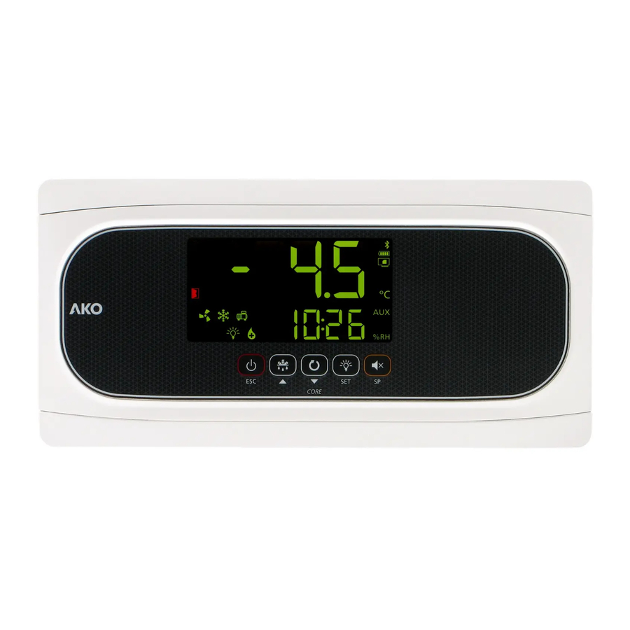
1662H402 Ed.01 Description Shows temperature Shows relative moisture / hour (in line with b23) Keypad Indicators Active heat provision, whether via evaporator Constant: Stand-By Mode activated. Regulation resistors or Hot Gas. is paused. Flashing: Controlled stop process for the Humidifier relay active. regulation in progress. - Page 5 1662H402 Ed.01 Keypad Pressing it for 3 seconds activates/deactivates the Stand-By mode. In this mode, regulation is paused and the m icon is displayed. In the programming menu, it exits the parameter without saving changes, returns to the previous level or exits programming.
-
Page 6: Installation
1662H402 Ed.01 Installation Ø Max. 20 mm -Remove the bezels (1) -Make a 1/4 turn of the screws (2) anti-clockwise and open the door (3). -Install the necessary glands (4 / 5) by drilling holes in the Ø Max. 25 mm points indicated on the box. -
Page 7: Initial Configuration
1662H402 Ed.01 Initial configuration The first time the unit receives the power supply, it will enter into ASSISTANT mode. The lower display will show the message In1 flashing with 0. Step 1: Cold regulation type Step 3: Temperature Set Point Use keys N and Q to enter the desired Set Point value Select the most suitable option based on the type of installation to be carried out and press SET. - Page 8 1662H402 Ed.01 In1 table Installation type (Cold regulation) Parameters Cold Pump Evaporator Defrost Pd o00 o80 I10 I11 d7 F3 regulation Down fans Demo mode: it displays the temperature but does not regulate the temperature or activate relays. Solenoid Electric Solenoid Solenoid Solenoid + compressor...
-
Page 9: Operation
1662H402 Ed.01 Operation Messages MESSAGES Pump down malfunction error (stop), the time configured in parameter C20 has been exceeded (see p. 15). Only displayed on screen. Pump down malfunction error (start-up), the time configured in parameter C19 has been exceeded (see p. 15). Only displayed on screen. - Page 10 1662H402 Ed.01 MESSAGES Password request. See parameters b10 and PAS (see p. 27). Only displayed on screen. Shown sequentially with the temperature: The controller is in demo mode, the configuration has not been made. Maximum moisture alarm in moisture probe. The temperature value programmed in A21 has been reached (see p.
- Page 11 1662H402 Ed.01 Cold regulation Solenoid control (COOL Relay) SPt+C1 Cold production is regulated by means of opening / closing the solenoid valve. When the temperature in probe S1 reaches the set point (SPt) value plus the probe's differential (C1), the solenoid opens and causes the temperature to drop.
- Page 12 1662H402 Ed.01 Compressor protection timing Parameter C4 allows for selection of the type of timing to be applied to protect the compressor. These delays prevent continuous compressor starts and stops. These timings affect the COOL and AUX 1 relays (if o00=1) OFF-ON (C4=0): Minimum time in OFF mode before each start-up.
- Page 13 1662H402 Ed.01 Regulation types, depending on the installation The controller’s priority is temperature regulation. Humidification + Dehumidification (via cold provision) - In2: 1 and 2 To increase moisture, the humidifier is activated and to reduce moisture, cold provision is activated, provided that the temperature is above the SPt.
- Page 14 1662H402 Ed.01 Operation in the event of a fault in probe SH If probe SH is faulty (failure, disconnection, etc.), the controller stops regulating moisture and shows the message EK on the lower display. Calibration of probe SH Parameter rH00 allows for correction of relative moisture as detected by probe SH; this is particularly useful when the probe cannot be located in the ideal place.
- Page 15 1662H402 Ed.01 Pump down function This function foresees problems in the compressor caused by movements of coolant, using a stop/start technique for the installation, controlled via the liquid solenoid, the low pressure switch and the compressor itself. This function is only available for In{ options 4, 5, and 6 and 12 and requires the connection of a low pressure switch in digital input 1.
- Page 16 1662H402 Ed.01 Defrost Types of defrost There are 5 possible defrost types, depending on the option selected in the wizard (In1): Electric (InI=1, 4 and 7) (d7=0) Defrost is performed through electrical resistors, supplying the evaporator with heat. The operation of fans in this mode depends on parameter F3;...
- Page 17 1662H402 Ed.01 Fan start-up delay This is established through parameter F4 and allows for the possible drops left in the evaporator to freeze before the fans activate, preventing them from being projected into the cold room. It also prevents heat being supplied to the cold room due to defrost in the evaporator.
- Page 18 1662H402 Ed.01 Anti-stratification function (Only if F2=1) This prevents layers of air of different temperatures (stratification) from forming inside the cold room by moving the air using the evaporator’s fans.T he fans are activated if they stop for a longer period than that defined in parameter F10 and deactivate once the time defined in F11 has elapsed.
- Page 19 1662H402 Ed.01 Temperature probe error alarm If one of the enabled probes is crossed, in open circuit or out of range, the message E1, E2 or E3 will be shown, depending on whether probe S1, S2 or S3 is involved. Evaporator probe error alarm due to moisture ingress If, at the start of defrost, the temperature in probe S2 is 20°C higher than the temperature in probe S1, the defrost ignores probe S2 and completes due to time-out.
-
Page 20: Alarm Delays
1662H402 Ed.01 Alarm delays These delays prevent certain alarms from being shown, to allow the installation to recover its normal operation after certain events. -Delays in start-up (A3): This delays the activation of the temperature and moisture alarms upon receiving power supply (start-up or after a power supply failure). - Page 21 1662H402 Ed.01 Password It allows protecting the configuration of the unit using a 2 digit code (from 01 to 99). If it is active a code is requested when you try to access the programming menu. This menu cannot be accessed if a wrong value is entered. The code is set via the PAS parameter. Parameter b10 defines the operation of this code.
-
Page 22: Configuration
1662H402 Ed.01 Configuration Condensed programming menu This allows for the most-used parameters to be quickly configured. Press the SET key for 3 seconds to access it. Condensed programming menu OUT OF IN PROGRAMMING PROGRAMMING 20 sec. Temperature Parameters Values indication 3 sec. - Page 23 1662H402 Ed.01 Extended programming menu Use the extended programming menu to configure all of the unit’s parameters in order to adapt it to your installation requirements. Press the SET key for 6 seconds to access it. IMPORTANT: If the password function has been configured as a keypad lock (b10=2), or as an access to parameters block (b10=1), you will be requested to enter the password programmed in PAS when attempting to access either of the two functions.
- Page 24 1662H402 Ed.01 Parameters Temperature regulation and control Description Values Min. Def. Max. Temperature setting (Set Point) ºC/ºF Probe 1 calibration (Offset) ºC/ºF -5.0 Probe 1 differential (Hysteresis) ºC/ºF 20.0 Set Point top locking (it cannot be set above this value) ºC/ºF Set Point bottom locking (it cannot be set below this value) ºC/ºF...
- Page 25 1662H402 Ed.01 Moisture regulation and control Description Values Min. Def. Max. Moisture setting (Moisture set point) % HR rX00 Moisture probe calibration (Offset) % HR rX01 Moisture probe differential (Hysteresis) % HR rX02 Upper locking of SPH (it cannot be set above this value) % HR rH03 rX03...
- Page 26 1662H402 Ed.01 Evaporator fans Description Values Min. Def. Max. Fan stop temperature via probe 2 ºC/ºF Probe 2 differential (Hysteresis) ºC/ºF 20.0 Shut down fans when the compressor shuts down 0=No 1=Yes Status of the fans during the defrost 0=Shut down; 1=Running Delay of start-up after defrost (If F3=0) Min.
-
Page 27: Inputs And Outputs
1662H402 Ed.01 Basic configuration Description Values Min. Def. Max. Delay of all functions on receiving power supply Min. Cold room light timing Min. Function of password 0=Inactive 1=Block access to parameters 2=Block keypad Access code (Password) MODBUS address Communication speed: 0=9600 bps 1=19200 bps 2=38400 bps 3=57600 bps... - Page 28 1662H402 Ed.01 Inputs and outputs Description Values Min. Def. Max. Configuration of relay AUX2 0=Deactivated 1=Alarm 2=Light 3=Virtual control 4=Solenoid for Hot Gas Configuración del relé AUX3 † 0=Desactivado 1=Heat resistor 2=Dehumidifier Configuration of DEF relay 0=Deactivated 1=Extractor fan 2=Defrost HUMID.
- Page 29 1662H402 Ed.01 Information (Reading only) Description Values Min. Def. Max. Option chosen in the In1 configuration wizard Option chosen in the In2 configuration wizard † Pump down active? 0=No 1=Yes Programme version Programme revision Bootloader version Bootloader revision Parameter map revision Exit to level 1 †...
-
Page 30: Connectivity
Once modified, the old address indicated on the plate will not be valid. AKO-5012 AKO-80039 AKO-80039 Tr-: Yellow RS-485 >25 ** Tr+: Orange GND: Black CAMRegis AKOGAS AKOControl* AKOALARM SECURE AKOControl* AKOCORE CONTROL Terminating resistors are not required. *AKO controller with communication **AKO-80024 Use if connecting more than 25 units... -
Page 31: Technical Specifications
Resolution, setting and differential ......................0.1 ºC Thermometric precision..........................±1 ºC Loading tolerance of the NTC probe at 25 °C....................±0.4 ºC Input for NTC probe ...........................AKO-14901 Working ambient temperature ......................-10 ºC a 50 ºC Storage ambient temperature ......................-30 ºC to 60 ºC Protection degree ............................IP 65... -
Page 32: Accessories
1662H402 Ed.01 Accessories AKO-58500 CAMM Module Together with the application for mobile devices, this module provides the unit with multiple functionalities: - Data logging - Activity summaries - Logging of configuration changes - Logging of events and alerts - Remote configuration... - Page 33 1662H402 Ed.01...
- Page 34 1662H402 Ed.01...
- Page 35 1662H402 Ed.01...
- Page 36 AKO ELECTROMECÁNICA , S.A.L. Avda. Roquetes, 30-38 08812 • Sant Pere de Ribes. Barcelona • Spain. Tel.: +34 902 333 145 Fax: +34 938 934 054 www.ako.com We reserve the right to supply materials that might vary slightly to those described in our Technical Sheets. Updated information is available on our website.
Need help?
Do you have a question about the AKO-16624 and is the answer not in the manual?
Questions and answers