
Subscribe to Our Youtube Channel
Related Manuals for ASEA AC125V-3


Summary of Contents for ASEA AC125V-3
- Page 1 Operations Manual for the ASEA Power Systems Model AC125V-3 3 Phase Yacht Power Converter P/N 605053 B Issued 4/27/2007...
-
Page 2: Warranty
LIFE SUPPORT POLICY ASEA Power Systems does not authorize the use of any of its products or systems for use an AC voltage supply (source) for life support systems. Life support systems are devices which support or sustain life, and whose failure to perform, when properly used in accordance with this Operations Manual, can be reasonably expected to result in significant injury to the user. -
Page 3: Using This Manual
If any questions arise while reading this manual, the user is encouraged to call ASEA Power Systems. ASEA Power Systems is located at: ASEA Power Systems 15602 Commerce Lane Huntington Beach, CA. -
Page 4: Table Of Contents
INTRODUCTION TO THE AC125V-3 ........ - Page 5 AC125V-3 Operations Manual..SOFTWARE FEATURES ..........40 GENERAL .
-
Page 6: Safety Notices
AC125V-3 Operations Manual..SAFETY NOTICES Each shore power converter is capable of transferring large amounts of electrical energy very quickly. This quality is fundamental to a high performance power converter. International symbols are used throughout this manual to stress important information. Read the text below each symbol carefully and use professional skills and prudent care when performing the actions described by the text. - Page 7 AC125V-3 Operations Manual..THIS EQUIPMENT CONTAINS HIGH ENERGY, LOW IMPEDANCE CIRCUITS! LETHAL POTENTIALS ARE CONTAINED WITHIN THE SYSTEM EVEN WHEN IT IS APPARENTLY NOT OPERATING. CARE MUST BE EXERCISED WHEN SERVICING THIS EQUIPMENT IN ORDER TO PREVENT SERIOUS OPERATOR INJURY OR EQUIPMENT DAMAGE.
-
Page 8: Introduction To The Ac125V-3
AC125V-3 Operations Manual..INTRODUCTION TO THE AC125V-3 The AC125V-3 is a high performance Yacht Power Converter utilizing dual-conversion technology. The system will accept any three phase input service with a frequency between 40-70Hertz, and a voltage between 330-520VAC. The output power form has been programmed at the factory for the voltage and frequency required by your yacht. - Page 9 AC125V-3 Operations Manual..components are packaged in one drip-proof, dust-resistant stainless steel enclosure. Major components are internally modular, allowing a simple exchange in the unlikely event of failure. Complete maintenance and service can be provided with only top and front access to the system.
-
Page 10: Specifications
AC125V-3 Operations Manual..SPECIFICATIONS ELECTRICAL SPECIFICATIONS Parameter AC125V-3 4.1.1 Input Service Input Power Form Three Phase Input Voltage Range 330-520V Input Frequency Range 40-70 Hertz Input Current, Max. Three Phase 189 A Input Current, Soft Start, Max. 30 A Input Current Distortion <8% THD @ rated load... - Page 11 AC125V-3 Operations Manual..SPECIFICATIONS ELECTRICAL SPECIFICATIONS cont. 4.1.2 Output Service, cont. Table 1 - Output Current, Rated Continuous RMS Output Form AC125V-3 3Ø, 277/480V 150A /Ø 3Ø, 254/440V 164A /Ø 3Ø, 240/416V 174A /Ø 3Ø, 230/400V 181A /Ø 3Ø, 220/380V 189A /Ø...
-
Page 12: Control, Metering, And Status
AC125V-3 Operations Manual..SPECIFICATIONS, cont. ELECTRICAL SPECIFICATIONS, cont. 4.1.3 Control, Metering, and Status Input Power Control Input Service Disconnect Switch, 2 pos. Shore Power Control Membrane Switch, Input ON/OFF Control Ship’s Power Control Membrane Switch, Output ON/OFF Control, Converter Power Control... -
Page 13: Installation
Table 2. Ensure the room/compartment has adequate ventilation and cooling. The thermal load presented by the converter will be substantial, approximately 20,313BTU/Hr at maximum continuous load for the AC125V-3. THE CONVERTERS ARE HEAVY, WEIGHING 1825lbs. -
Page 14: Mechanical Installation
AC125V-3 Operations Manual..MECHANICAL INSTALLATION The converters were designed for deck mount installations and as such are provided with ten mounting holes. Mounting holes have been provided with ½” (12.7mm) diameters; stainless steel hardware in the range of 3/8” to 7/16” (10-11mm) diameter is required. -
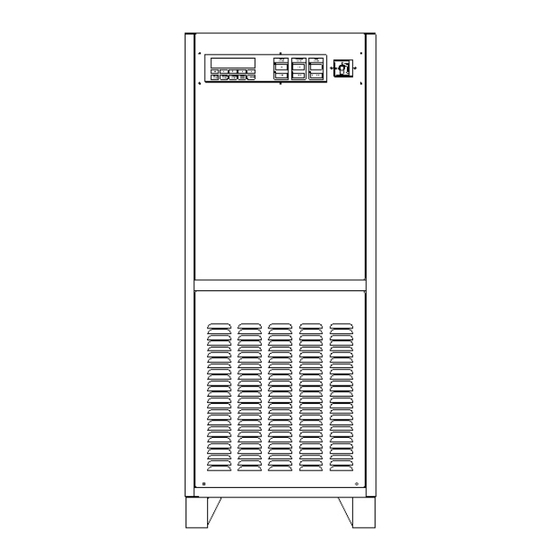
Page 15: Mechanical Outline
AC125V-3 Operations Manual..MECHANICAL INSTALLATION, cont. FIGURE 2 MECHANICAL OUTLINE... -
Page 16: Controls
AC125V-3 Operations Manual..MECHANICAL INSTALLATION, cont. FIGURE 3 CONTROLS... -
Page 17: Electrical Installation
WITH STANDARD SAFEGUARDS AND PROCEDURES REQUIRED BY THE INSTALLATION OF THIS TYPE OF EQUIPMENT. POWER MUST BE REMOVED FROM THE INPUT DISTRIBUTION SYSTEMS SUPPLYING POWER TO THE AC125V-3 PRIOR TO THE START OF THE FOLLOWING STEPS. INPUT POWER MUST BE SECURED (LOCKED) IN THE OFF (DE-ENERGIZED) STATE UNTIL INSTRUCTED OTHERWISE BY THIS DOCUMENT. -
Page 18: Input Power Connections
AC125V-3 Operations Manual..5.2.1 Input Power Connections The converter is supplied with compression type terminal blocks for input power connections. These terminal blocks accept wires in the range of 350MCM to 6AWG. Refer to the applicable standards for selection of required wire gauge and type. - Page 19 AC125V-3 Operations Manual..THE CONVERTER ISOLATES THE OUTPUT POWER FROM THE INPUT POWER AND EQUIPMENT (SAFETY) GROUNDS SIMILAR TO AN ISOLATION TRANSFORMER. THE INSTALLER MUST RE-ESTABLISH THE GROUND REFERENCE FOR THE EQUIPMENT AT TIME OF INSTALLATION. NEUTRAL AND EQUIPMENT (SAFETY) GROUNDS TO BE CONNECTED PER ABYC STANDARDS.
- Page 20 AC125V-3 Operations Manual..This page intentionally left blank.
-
Page 21: Seamless Transfer Connections
AC125V-3 Operations Manual..5.2.3 Seamless Transfer Connections If the Seamless Transfer Option was ordered with the system, connections must be made between the generator and the converter. These connections are used by the converter to successfully manage the seamless transfer operation and are comprised of control, signal, and feedback functions. These connections are only required on the Master cabinet of a multi-cabinet installation. -
Page 22: Seamless Transfer Pcb Connections
AC125V-3 Operations Manual..5.2.3 Seamless Transfer Connections, cont. FIGURE 5 SEAMLESS TRANSFER PCB CONNECTIONS... -
Page 23: Multi-Cabinet
AC125V-3 Operations Manual..5.2.4 Multi-Cabinet System Interconnection All multi-cabinet systems are constructed from one cabinet which serves as the system Master, and a second cabinet which serves as the Slave. A paralleling cable assembly (P/N 605150) is shipped pre-connected to the Slave cabinet and coiled at the base of the cabinet near the Input and Output connection terminal blocks. -
Page 24: Operation
AC125V-3 Operations Manual..OPERATION POWER TURN-ON PROCEDURE Close the shore power (input) circuit breaker or switch to the converter. Turn the disconnect (14) switch to the ON position. After 1-3 seconds, fans will be heard, and the display will become active. - Page 25 AC125V-3 Operations Manual..POWER TURN-ON PROCEDURE, cont. The display will sequence to the SUMMARY DISPLAY indicating the converter’s operational state. Both input and output (converter) should indicate OFFLINE at this time. Return to this screen at any time by pressing the SYSTEM STATUS (5) button.
-
Page 26: Systems Without Seamless Transfer
AC125V-3 Operations Manual..POWER TURN-ON PROCEDURE, cont. Press the CONVERTER POWER (4) button and the screen will now change. As with the shore power displays, the F1-F4 (13) buttons will cycle through a variety of converter power data. Output voltages and currents should indicate zero. -
Page 27: Systems With Seamless Transfer
AC125V-3 Operations Manual..POWER TURN-ON PROCEDURE, cont. 6.1.2 Systems Equipped With The Seamless Transfer Option With the converter in the Standby State (as left at the end of Section 6.1), press the GENERATOR POWER (3) display button. The generator voltage and form will now be displayed. - Page 28 AC125V-3 Operations Manual..POWER TURN-ON PROCEDURE, cont. 6.1.2 Systems Equipped With The Seamless Transfer Option, cont. If the generator is supplying power to the ship, the SHIP’S POWER - GENERATOR LED (12A) is lit, and the GENERATOR metering display indicates approximately the same voltage as the CONVERTER metering display, then proceed by pressing the SHIP’S POWER - CONVERTER (9)
-
Page 29: Multi-Cabinet Turn-On Procedure
AC125V-3 Operations Manual..MULTI-CABINET OPERATION Multi-cabinet systems are operated from the Master’s control panel. Each cabinet retains its own control panel and metering display for individual monitoring. A load management option exists that allows individual cabinets to load according to shore cord size: contact the factory for details. - Page 30 AC125V-3 Operations Manual..This page intentionally left blank.
-
Page 31: Auto-Restart Feature
AC125V-3 Operations Manual..AUTO-RESTART FEATURE The Auto-Restart feature will safely and automatically bring the shore power converter back on- line following a power failure and recovery event. Highlights include: Automatically routes power from the dock to the ships power buss. - Page 32 AC125V-3 Operations Manual..AUTO-RESTART FEATURE, cont. 6.3.1 Operation Auto-Restart must be enabled from the converter front panel by simultaneously pressing two buttons. Anytime the system status is “FAILURE,” the converter will disable the Auto-Restart feature. The converter must be ON and ONLINE before Auto-Restart may be enabled. Pressing the SYSTEM STATUS button (5) will display the SUMMARY DISPLAY which will indicate the Auto-Restart status.
-
Page 33: Turn-Off Procedure
AC125V-3 Operations Manual..TURN-OFF PROCEDURE 6.4.1 Systems Not Equipped With The Seamless Transfer Option Transfer power from the converter to the generator. This must be performed in a “break-before- make” method, that is, at no time can the generator(s) and shore power converter be operated in parallel. -
Page 34: Systems With Seamless Transfer
AC125V-3 Operations Manual..6.4.2 Systems Equipped With The Seamless Transfer Option The generator must be started and be prepared to accept the ships’s electrical loads. Measure the generator voltage using the converter’s metering display, selecting the GENERATOR POWER (3) function. The voltage and frequency must be the same as the converter’s output in order for the seamless transfer option to successfully transfer power. -
Page 35: Remote Communication
The Baud Rate can be increased by pressing the F1 (13) button, and decreased by pressing the F2 (13) button. Pressing SYSTEM STATUS (5) saves the setting. Standard baud rates are 1200, 2400, 4800, 9600, 19200, and 38400 where 19200 is the standard for communication with ASEA Power Systems Touch Screens. -
Page 36: Rs-232C Pinout
AC125V-3 Operations Manual..REMOTE COMMUNICATIONS, cont. FIGURE 7 RS-232C PIN-OUT... - Page 37 AC125V-3 Operations Manual..REMOTE COMMUNICATIONS, cont. Remote control can be accomplished with the use of an ASEA Power Systems defined Remote Communication Command Set, or through visual touch screen software that is described elsewhere. Many standard serial communication programs have been tested with the RS-232C Command Set and were found to function adequately.
- Page 38 AC125V-3 Operations Manual..REMOTE COMMUNICATIONS, cont. Command Description Comment :SHORe:ON Shore Power ON Same as pressing the Shore Power ON button on the panel. :SHORe:OFF Shore Power OFF Same as pressing the Shore Power OFF button on the panel. :CONVerter:ON...
- Page 39 AC125V-3 Operations Manual..REMOTE COMMUNICATIONS, cont. Command Description Return Value Range :MEASure:SP1:CURRent1 Shore Power A RM S Current Real number, 0 to 1000 :MEASure:SP1:CURRent2 Shore Power B RM S Current Real number, 0 to 1000 :MEASure:SP1:CURRent3 Shore Power C RM S Current...
-
Page 40: Software Features
SOFTWARE FEATURES GENERAL ASEA Power Systems' shore power converters provide a variety of software-based resources. Each major function is described in detail in the following pages. BOLD upper-case text indicates when a display button is being referenced. Where two buttons are given as BUTTON + BUTTON, the buttons must be pressed simultaneously. - Page 41 AC125V-3 Operations Manual..LOAD MANAGEMENT, cont. Load Sharing The slave converter of a paralleled converter system can be forced to draw less current than the master converter, if attached to a shore cord with lesser available power due to lower amperage, or lower voltage.
-
Page 42: Load Management Operation
AC125V-3 Operations Manual..LOAD MANAGEMENT OPERATION 7.3.1 Shore Cord Alarm, Single, Master, and Slave converters If the yacht’s electrical system includes a power management or load-shed feature, the Shore Cord Alarm can be used to effect a change in loading when the converter reaches a programmed load threshold, or simply draw the yacht engineer’s attention. -
Page 43: Shore Cord Setup, Single, Master, Or Slave Converters
AC125V-3 Operations Manual..LOAD MANAGEMENT OPERATION, cont. 7.3.2 Shore Cord Setup, Single, Master, or Slave Converters The Shore Cord Setup screen is used to set the actual shore cord ampacity based on the marina’s dock or pedestal circuit breaker. The converter’s new, programmed CONV. CAPACITY is then displayed for reference. -
Page 44: Load Sharing, Slave Converters With Shore Cord Management Option
AC125V-3 Operations Manual..LOAD MANAGEMENT OPERATION, cont. 7.3.3 Load Sharing, Slave converters with Shore Cord Management Option The function of this special Slave converter screen includes those functions of the normal Shore Cord Setup screen described on the previous page with one addition: Load Sharing between the two converters of a paralleled converter system is controlled by entering the MASTER CAPACITY here. - Page 45 AC125V-3 Operations Manual..LOAD MANAGEMENT OPERATION, cont. 7.3.3 Load Sharing, Slave converters with Shore Cord Management Option, cont. From the front panel, press the SHORE POWER + F2 buttons, and then Cord (F1) to access the following screen: LOAD SHARING MASTER CAPACITY:125.0kVA...
-
Page 46: Voltage Droop, Single Or Master Converters
AC125V-3 Operations Manual..LOAD MANAGEMENT OPERATION, cont. 7.3.4 Voltage Droop, Single or Master Converters Upon Shore Alarm, the Voltage Droop feature may be used to save up to 10% converter capacity by reducing the converter output voltage up to 5%. This is offered as a solution where the yacht does not already have power management and load-shed capabilities that can be triggered with the Shore Cord Alarm signal. -
Page 47: Automatic Transfer To Generator, Single Or Master Converters
AC125V-3 Operations Manual..LOAD MANAGEMENT OPERATION, cont. 7.3.5 Automatic Transfer to Generator, Single or Master Converters (Seamless Transfer installed) Upon Shore Alarm, the Automatic Transfer to Generator feature may be used to perform a Seamless Transfer to a pre-selected generator. This implies connection and setting of the Generator Autostart Control feature (needed to signal a generator to start and hold the set warm-up time before transferring). -
Page 48: Quick Setup Of Shore Cord Alarm, Single, Master, Or Slave Converters
AC125V-3 Operations Manual..LOAD MANAGEMENT OPERATION, cont. 7.3.6 Quick Setup of Shore Cord Alarm, Single, Master, or Slave Converters 1. Turn on the red Disconnect switch of both converters and wait 15-20 seconds for initialization. 2. Press the SHORE POWER + F2 buttons on both converters. -
Page 49: Expert Load Sharing Use, Paralleled Converters
AC125V-3 Operations Manual..LOAD MANAGEMENT OPERATION, cont. 7.3.7 Expert Load Sharing Use, Paralleled Converters The Load Sharing system described in this document has been programmed for simple use and comprehensive gathering of all pertinent data into a few, simple screens. However, the controls can be bypassed and Load Sharing implemented by the user directly via the Slave’s programmable... -
Page 50: Generator Frequency Analysis
AC125V-3 Operations Manual..GENERATOR FREQUENCY ANALYSIS Press the SYSTEM STATUS + GENERATOR POWER buttons to access the Generator Frequency Analysis Display. Used for observing lifetime generator frequency range. GENERATOR FREQUENCY ANALYSIS DISPLAY Generator MIN Frequency: XX.XXHz Generator MAX Frequency: XX.XXHz... -
Page 51: Agc Control
AC125V-3 Operations Manual..AGC CONTROL Press the SHORE POWER + F4 buttons to access the Automatic Gain Control (AGC) CONTROL display. AGC CONTROL SCREEN Automatic Gain Control is: ENABLED Enable Disable Exit This function enables or disables AGC. Press the Enable (F1) button to enable the feature, the Disable (F2) button to disable the feature, and the Exit (F5) button to save the settings and exit. -
Page 52: Kw-Hour Meter And Maximum Power Level Display
AC125V-3 Operations Manual..kW-HOUR METER AND MAXIMUM POWER LEVEL DISPLAY Press the SHORE POWER + CONVERTER POWER buttons to access the Automatic KW-HOUR METER and maximum power level display. KW-HOUR METER kW-Hours:XXXXXXX.XX Run Time. XX:XX:XX:XX Max. Level: XXX.X% Max. Power: XX.XXkW... -
Page 53: Converter Output Voltage Control
AC125V-3 Operations Manual..CONVERTER OUTPUT VOLTAGE CONTROL Press the CONVERTER POWER + F5 buttons to access the CONVERTER OUTPUT VOLTAGE CONTROL display. CONVERTER OUTPUT VOLTAGE CONTROL Vout = XXX.X More Less XXXV Exit This function allows the user to increase or decrease the converter output voltage (Vout). Press the... -
Page 54: Event Log
AC125V-3 Operations Manual..EVENT LOG Press the EVENT LOG (or CALIBRATE on older converters) button to access the EVENT LOG display. EVENT LOG CONTROL SCREEN F1: EVENT LOG VIEWER XXXX Events F2: EVENT LOG TRACKER F3: EVENT LOG REGISTRY This is for monitoring internal converter logic operation. Press the SYSTEM STATUS button in any screen to exit. - Page 55 AC125V-3 Operations Manual..EVENT LOG, cont. Press the F3 button to access the EVENT LOG REGISTRY display. EVENT LOG REGISTRY PRESS: ‘SHORE POWER’ to edit Registry, The ‘F1’ for log On & ‘F2’ for log Off. Press: ‘F4’ to CLEAR EVENT LOG.
-
Page 56: Diagnostics
AC125V-3 Operations Manual..DIAGNOSTICS As previously described in paragraph 6.1, the converter’s LCD display will initiate on turn-on in the SUMMARY DISPLAY indicating the converter’s operational state. Return to this screen at any time by pressing the SYSTEM STATUS (5) button. In the event of a converter failure or over- temperature condition, “WARNING”... - Page 57 AC125V-3 Operations Manual..DIAGNOSTICS, cont. To aid in system diagnostics, three status words have been provided in the STATUS WORD DISPLAY which is accessed by pressing the SYSTEM STATUS (5) and F2 (13) buttons simultaneously. BIT: FEDCBA9876543210 CON: XXXXXXXX SW1: XXXXXXXXXXXXXXXX...
-
Page 58: Status Word Bit Definitions
AC125V-3 Operations Manual..DIAGNOSTICS, cont. FIGURE 8 STATUS WORD BIT DEFINITIONS... -
Page 59: Calibration
AC125V-3 Operations Manual..CALIBRATION In an uncalibrated state the input and output voltage and input current metering system should be within 5%. The uncalibrated output current meter is normally 10% low. For calibration an external reference voltmeter will be required along with a calibrated current transformer or probe. If the system is to be calibrated on board using the yacht’s loads, attempt to shut down all transient (fluctuating) loads if... - Page 60 AC125V-3 Operations Manual..CALIBRATION, cont. Generator Power Calibration - Use an external reference voltmeter to measure the generator voltage at the generator terminals located on TB12-1, 2, 3, 4. To enter the meter calibration screen, press and hold the GENERATOR POWER (3) button down for 7 seconds, or until the calibration display appears, then release the button.
-
Page 61: Maintenance
AC125V-3 Operations Manual..MAINTENANCE Due to the design and construction of the converter, preventative maintenance is held to a modest level. The following table lists minimum recommended tasks and frequency. TASK FREQUENCY COMMENTS Tighten electrical Every 6 months Must be adjusted by the user based upon connections experience in the environment. -
Page 62: International Power Form Reference
AC125V-3 Operations Manual..INTERNATIONAL POWER FORM REFERENCE Country Frequency Nominal Voltage Comments American Samoa 60Hz 120/240 277/480 Antigua 60Hz 230/400 Argentina 50Hz 220/380 Aruba 60Hz 127/220 115/230 Australia 50Hz 240/415 250/435 Azores 50Hz 110/190 220/380 Bahamas 60Hz 120/240 120/208 Bahrain... - Page 63 AC125V-3 Operations Manual..Bulgaria 50Hz 220/380 Burma 50Hz 230/400 Canada 60Hz 120/240 120/208 277/480 Canary Islands 50Hz 127/220 220/380 Cape Verde 50Hz 220/380 Cayman Islands 60Hz 120/240 120/208 Chile 50Hz 220/380 China (PRC) 50Hz 220/380 Columbia 60Hz 110/220 120/208 150/260...
- Page 64 AC125V-3 Operations Manual..Greenland 50Hz 220/380 Grenada 50Hz 230/400 Guadeloupe 50Hz 220/380 Guam 60Hz 110/220 120/208 Guatemala 60Hz 120/240 120/208 Haiti 60Hz 110/220 120/208 Honduras 60Hz 110/220 120/208 Hong Kong 50Hz 220/380 Ireland 50Hz 220/380 Israel 50Hz 230/400 Italy 50Hz...
- Page 65 AC125V-3 Operations Manual..Mexico 60Hz 127/220 Monaco 50Hz 127/220 220/380 Montserrat 60Hz 230/400 Morocco 50Hz 127/220, 220/380, 230/400 Netherlands 50Hz 220/380, 230/400 Netherlands 50Hz 127/220 Antilles 220/380 60Hz 120/240 New Caledonia 50Hz 220/380 New Zealand 50Hz 230/400 Norway 50Hz 230/400...
- Page 66 AC125V-3 Operations Manual..Sweden 50Hz 220/380 Tahiti 60Hz 127/220 Taiwan 60Hz 110/220 120/208 Thailand 50Hz 220/380 Togo 50Hz 127/220 220/380 Trinidad 60Hz 115/230 230/400 Tunisia 50Hz 127/220 220/380 United Arab 50Hz 230/400 Emirates United Kingdom 50Hz 240/415 Uruguay 50Hz 220/380...
Need help?
Do you have a question about the AC125V-3 and is the answer not in the manual?
Questions and answers