
Subscribe to Our Youtube Channel
Related Manuals for ASEA AC100Q-3


Summary of Contents for ASEA AC100Q-3
- Page 1 Operations Manual for the ASEA Power Systems Model AC100Q-3 3 Phase Yacht Power Converter 619051 Issued 9/24/2012...
-
Page 2: Certification
LIFE SUPPORT POLICY ASEA Power Systems does not authorize the use of any of its products or systems for use an AC voltage supply (source) for life support systems. Life support systems are devices which support or sustain life, and whose failure to perform, when properly used in accordance with this Operations Manual, can be reasonably expected to result in significant injury to the user. -
Page 3: Using This Manual
A thorough understanding of the information covered in this manual is required for proper installation and operation. If any questions arise while reading this manual, the user is encouraged to call ASEA Power Systems. ASEA Power Systems is located at:... -
Page 4: Table Of Contents
AC100Q-3 Operations Manual..TABLE OF CONTENTS CERTIFICATION ...........................2 WARRANTY ..........................2 USING THIS MANUAL .....................3 SAFETY NOTICES......................6 INTRODUCTION TO THE CONVERTER ...............8 SPECIFICATIONS ......................10 ELECTRICAL SPECIFICATIONS ..............10 4.1.1 Input Service ....................10 4.1.2 Output Service ...................10 4.1.3 Control, Metering, and Status ..............12 PHYSICAL SPECIFICATIONS ................12... - Page 5 AC100Q-3 Operations Manual..SOFTWARE FEATURES ....................39 GENERAL ......................39 LOAD MANAGEMENT..................39 LOAD MANAGEMENT OPERATION ...............41 7.3.1 Shore Cord Alarm, Single, Master, and Slave converters ......41 7.3.2 Shore Cord Setup, Single, Master, or Slave Converters ......42 7.3.3 Voltage Droop, Single or Master Converters ..........43 7.3.4 Automatic Transfer to Generator, Single or Master Converters (Seamless...
-
Page 6: Safety Notices
AC100Q-3 Operations Manual..SAFETY NOTICES Each shore power converter is capable of transferring large amounts of electrical energy very quickly. This quality is fundamental to a high performance power converter. International symbols are used throughout this manual to stress important information. Read the text below each symbol carefully and use professional skills and prudent care when performing the actions described by the text. - Page 7 AC100Q-3 Operations Manual.. THIS EQUIPMENT CONTAINS HIGH ENERGY, LOW IMPEDANCE CIRCUITS! LETHAL POTENTIALS ARE CONTAINED WITHIN THE SYSTEM EVEN WHEN IT APPEARS NON-OPERATIONAL. CARE MUST BE EXERCISED WHEN SERVICING THIS EQUIPMENT IN ORDER TO PREVENT SERIOUS OPERATOR INJURY OR EQUIPMENT DAMAGE.
-
Page 8: Introduction To The Converter
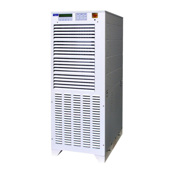
AC100Q-3 Operations Manual..INTRODUCTION TO THE CONVERTERS The AC100Q-3 is a high performance Yacht Power Converter utilizing dual-conversion technology. The systems will accept any three phase input service with a frequency between 40-70Hertz, and a voltage between 170-520VAC (with limited power capabilities while operating within the under-300VAC input voltage range). - Page 9 AC100Q-3 Operations Manual..Being a converter designed from the ground up specifically for the yachting industry, all efforts have been made to produce a system capable of withstanding the marine environment. The system is constructed using a modular approach where the converter consists of a control module (upper), three power modules (middle), and a transformer module (bottom).
-
Page 10: Specifications
AC100Q-3 Operations Manual..SPECIFICATIONS ELECTRICAL SPECIFICATIONS Parameter AC100Q-3 4.1.1 Input Service Input Power Form Three Phase Input Voltage Range 170-520V Input Frequency Range 40-70 Hertz Input Current, Max. Three Phase Input Current, Soft Start, Max. Input Current Distortion <8% THD @ rated load Input Power Factor >0.98 @ rated load... - Page 11 AC100Q-3 Operations Manual..SPECIFICATIONS ELECTRICAL SPECIFICATIONS cont. 4.1.2 Output Service, cont. Table 1 - Output Current, Rated Continuous RMS (Select converter output form specified; read output current for input form in use) Input Form Input Form Input Form Output Form 3Ø, 400V...
-
Page 12: Control, Metering, And Status
AC100Q-3 Operations Manual..SPECIFICATIONS, cont. ELECTRICAL SPECIFICATIONS, cont. 4.1.3 Control, Metering, and Status Input Power Control Input Service Disconnect Switch, 2 pos. Shore Power Control Membrane Switch, Input ON/OFF Control Converter Power Control Membrane Switch, Output ON/OFF Control, Ship’s Power Control... -
Page 13: Installation
Table 2. Ensure the room/compartment has adequate ventilation and cooling. The thermal load presented by the converter will be substantial, approximately 21,850BTU/Hr at maximum continuous load for the AC100Q-3. THE CONVERTER IS HEAVY, WEIGHING 1,583lbs. (718kg) EXTREME CAUTION MUST BE EXERCISED IN HANDLING AND INSTALLATION TO AVOID EQUIPMENT DAMAGE OR INJURY TO PERSONNEL. -
Page 14: Mechanical Installation
AC100Q-3 Operations Manual..MECHANICAL INSTALLATION The converters were designed for deck mount installations and as such are provided with eight mounting holes. Mounting holes have been provided with 0.56” (14.2mm) diameters; ½” (13mm) stainless steel hardware is required. The mounting surface should be flat and dimensionally stable to within 1/16” (1.5mm) to prevent torsional stresses being applied to the structure of the converter. -
Page 15: Mechanical Outline
AC100Q-3 Operations Manual..MECHANICAL INSTALLATION, cont. FIGURE 2 MECHANICAL OUTLINE... -
Page 16: Controls
AC100Q-3 Operations Manual..MECHANICAL INSTALLATION, cont. FIGURE 3 MECHANICAL OUTLINE... -
Page 17: Electrical Installation
AC100Q-3 Operations Manual..ELECTRICAL INSTALLATION This procedure assumes the physical installation of the converter has been completed. It is the installer’s responsibility to provide input service over-current protection and disconnect means. It is recommended that connection be made to the distribution bus through a manually operated... -
Page 18: Input Power Connections
THE INSTALLATION OF THIS TYPE OF EQUIPMENT. POWER MUST BE REMOVED FROM THE INPUT DISTRIBUTION SYSTEMS SUPPLYING POWER TO THE AC100Q-3 PRIOR TO THE START OF THE FOLLOWING STEPS. INPUT POWER MUST BE SECURED (LOCKED) IN THE OFF (DE-ENERGIZED) STATE UNTIL INSTRUCTED OTHERWISE BY THIS DOCUMENT. -
Page 19: Input And Output Connections
AC100Q-3 Operations Manual..ELECTRICAL INSTALLATION, cont. FIGURE 4 INPUT AND OUTPUT CONNECTIONS Prepare the power cables by removing approximately 6” of the outer cable insulation (in the case of SO type portable cables). Strip the insulation back exposing the appropriate amount of the bare conductor for the chosen 3/8”... -
Page 20: Grounding
AC100Q-3 Operations Manual..ELECTRICAL INSTALLATION, cont. 5.2.3 Grounding The converter chassis ground MUST be connected to the ship’s hull or common ground point via the compression fitting terminal adjacent to the output power connections. Failure to do so may create conditions that may in turn cause injury or death to operators; failure to do so will also result in the voiding of the equipment warranty. -
Page 21: Multi-Cabinet Connections
AC100Q-3 Operations Manual..ELECTRICAL INSTALLATION, cont. 5.2.4 Multi-Cabinet Connections Multi-cabinet systems should have each cabinet’s output connections paralleled at the switchgear panel. The converters’ terminal blocks are sized for a single, appropriated sized cable per phase, neutral, and grounding conductor. -
Page 22: Seamless Transfer Connections
AC100Q-3 Operations Manual..ELECTRICAL INSTALLATION, cont. 5.2.5 Seamless Transfer Connections If the Seamless Transfer Option was ordered with the system, connections must be made between the generator/switchgear and converter. These connections are used by the converter to successfully manage Seamless Transfer operation and are comprised of control, signal, and feedback functions. -
Page 23: Other Optional Connections
AC100Q-3 Operations Manual..ELECTRICAL INSTALLATION, cont. 5.2.6 Other Optional Connections In support of the Seamless Transfer Option, or in support of switchgear and/or power monitoring integration, other options may be ordered and installed in a converter. Installation requirements for such options vary in accordance with switchgear design and hence are beyond the scope of this Operations Manual. -
Page 24: Operation
AC100Q-3 Operations Manual..OPERATION POWER TURN-ON PROCEDURE Close the shore power (input) circuit breaker or switch to the converter. Turn the disconnect (14) switch to the ON position. After 1-3 seconds, fans will be heard, and the display will become active. - Page 25 AC100Q-3 Operations Manual..POWER TURN-ON PROCEDURE, cont. The display will sequence to the SUMMARY DISPLAY indicating the converter’s operational state. Both input and output (converter) should indicate OFFLINE at this time. Press the INFO (13) button to review the Shore Power state if desired. The INFO screen will either list the Shore Power as ONLINE or give a reason for its being off if it was previously on.
-
Page 26: Systems Not Equipped With The Seamless Transfer Option
AC100Q-3 Operations Manual..POWER TURN-ON PROCEDURE, cont. Press the CONVERTER POWER (4) button and the screen will now change. As with the shore power displays, the F1-F4 (13) buttons will cycle through a variety of converter power data. Output voltages and currents should indicate zero. -
Page 27: Systems Equipped With The Seamless Transfer Option
AC100Q-3 Operations Manual..POWER TURN-ON PROCEDURE, cont. 6.1.2 Systems Equipped With The Seamless Transfer Option With the converter in the Standby State (as left at the end of Section 6.1), press the GENERATOR POWER (3) display button. The generator voltage and form will now be displayed. - Page 28 AC100Q-3 Operations Manual..POWER TURN-ON PROCEDURE, cont. 6.1.2 Systems Equipped With The Seamless Transfer Option, cont. If the generator is supplying power to the ship, the SHIP’S POWER - GENERATOR LED (12A) is lit, and the GENERATOR metering display indicates approximately the same voltage as the CONVERTER metering display, then proceed by pressing the SHIP’S POWER - CONVERTER...
-
Page 29: Multi-Cabinet Turn-On Procedure
AC100Q-3 Operations Manual..MULTI-CABINET OPERATION Multi-cabinet systems are operated from the Master’s control panel. Each cabinet retains its own control panel and metering display for individual monitoring. A load management option exists that allows individual cabinets to load according to shore cord size (see section 7 for details). -
Page 30: Auto-Restart Feature
AC100Q-3 Operations Manual..AUTO-RESTART FEATURE The Auto-Restart feature will safely and automatically bring the shore power converter back on-line following a power failure and recovery event. Highlights include: Automatically routes power from the dock to the ship’s power buss. -
Page 31: Operation
AC100Q-3 Operations Manual..AUTO-RESTART FEATURE, cont. 6.3.1 Operation Auto-Restart must be enabled from the converter front panel by simultaneously pressing two buttons. Anytime the system status is “FAILURE,” the converter will disable the Auto-Restart feature. The converter must be ON and ONLINE before Auto-Restart may be enabled. Pressing the SYSTEM STATUS button (5) will display the SUMMARY DISPLAY which will indicate the Auto-Restart status. -
Page 32: Turn-Off Procedure
AC100Q-3 Operations Manual..TURN-OFF PROCEDURE 6.4.1 Systems Not Equipped With The Seamless Transfer Option Transfer power from the converter to the generator. This must be performed in a “break-before-make” method. That is to say that at no time can the generator(s) and shore power converter be operated in parallel. -
Page 33: Systems Equipped With The Seamless Transfer Option
AC100Q-3 Operations Manual..6.4.2 Systems Equipped With The Seamless Transfer Option The generator must be started and be prepared to accept the ship’s electrical loads. Measure the generator voltage using the converter’s metering display, selecting the GENERATOR POWER (3) function. The voltage and frequency must be the same as the converter’s output in order for the seamless transfer option to successfully transfer power. -
Page 34: Remote Communication
RS-485 standard via a din-rail mounted converter/optical-isolator. The two software protocols supported by the converter are SCPI and Modbus. Please contact an ASEA Power Systems authorized distributor or the factory for additional information and comprehensive command/query listings. The Baud Rate and fixed serial port settings can be viewed in the REMOTE INTERFACE CONFIGURATION DISPLAY (as depicted below) by pressing the SYSTEM STATUS (5) and F3 (13) buttons simultaneously. -
Page 35: Rs-232C/Scpi
AC100Q-3 Operations Manual..REMOTE COMMUNICATIONS, cont. 6.5.1 RS-232C/SCPI The RS-232C serial port is located in the upper-left corner of the Input/Output connection panel (see Figure 4 on page 19). The RS-232C TxD signal originating in the converter is approximately +15V when “High” and -15V when “Low.”... -
Page 36: Rs-485/Modbus
AC100Q-3 Operations Manual..REMOTE COMMUNICATIONS, cont. 6.5.2 RS-485/Modbus If included in the converter, a Modbus Option converter/optical-isolator will be located adjacent to the RS-232C serial port (see Figure 4 on page 19). The Modbus Option included converter/optical-isolator connections are depicted in Figure 7 below. - Page 37 ASEA Power Systems designed Touch Panel computers. Additional slave converters can be set for Node Id numbers greater than 4 (5-8 recommended). As ASEA Power Systems uses Node Id numbers 9-13 for GMM products, use of these should be avoided.
- Page 38 AC100Q-3 Operations Manual..This page intentionally left blank...
-
Page 39: Software Features
SOFTWARE FEATURES GENERAL ASEA Power Systems' shore power converters provide a variety of software-based resources. Each major function is described in detail in the following pages. BOLD upper-case text indicates when a display button is being referenced. Where two buttons are given as BUTTON + BUTTON, the buttons must be pressed simultaneously. - Page 40 AC100Q-3 Operations Manual..LOAD MANAGEMENT, cont. Load Sharing The slave converter of a paralleled converter system can be forced to draw less current than the master converter, if attached to a shore cord with lesser available power due to lower amperage, or lower voltage.
-
Page 41: Load Management Operation
AC100Q-3 Operations Manual..LOAD MANAGEMENT OPERATION 7.3.1 Shore Cord Alarm, Single, Master, and Slave converters If the yacht’s electrical system includes a power management or load-shed feature, the Shore Cord Alarm can be used to effect a change in loading when the converter reaches a programmed load threshold, or simply draw the yacht engineer’s attention. -
Page 42: Shore Cord Setup, Single, Master, Or Slave Converters
AC100Q-3 Operations Manual..LOAD MANAGEMENT OPERATION, cont. 7.3.2 Shore Cord Setup, Single, Master, or Slave Converters The Shore Cord Setup screen is used to set the actual shore cord ampacity based on the marina’s dock or pedestal circuit breaker. The converter’s new, programmed CONV. CAPACITY is then displayed for reference. -
Page 43: Voltage Droop, Single Or Master Converters
AC100Q-3 Operations Manual..LOAD MANAGEMENT OPERATION, cont. 7.3.3 Voltage Droop, Single or Master Converters Upon Shore Alarm, the Voltage Droop feature may be used to save up to 10% converter capacity by reducing the converter output voltage up to 5%. This is offered as a solution where the yacht does not already have power management and load-shed capabilities that can be triggered with the Shore Cord Alarm signal. -
Page 44: Automatic Transfer To Generator, Single Or Master Converters (Seamless Transfer Installed)
AC100Q-3 Operations Manual..LOAD MANAGEMENT OPERATION, cont. 7.3.4 Automatic Transfer to Generator, Single or Master Converters (Seamless Transfer installed) Upon Shore Alarm, the Automatic Transfer to Generator feature may be used to perform a Seamless Transfer to a pre-selected generator. This implies connection and setting of the Generator Autostart Control feature (needed to signal a generator to start and hold the set warm-up time before transferring). -
Page 45: Quick Setup Of Shore Cord Alarm, Single, Master, Or Slave Converters
AC100Q-3 Operations Manual..LOAD MANAGEMENT OPERATION, cont. 7.3.5 Quick Setup of Shore Cord Alarm, Single, Master, or Slave Converters 1. Turn on the red Disconnect switch of both converters and wait 15-20 seconds for initialization. 2. Press the SHORE POWER + F2 buttons on both converters. -
Page 46: Generator Frequency Analysis
AC100Q-3 Operations Manual..GENERATOR FREQUENCY ANALYSIS Press the SYSTEM STATUS + GENERATOR POWER buttons to access the Generator Frequency Analysis Display. Used for observing lifetime generator frequency range. GENERATOR FREQUENCY ANALYSIS DISPLAY Generator MIN Frequency: XX.XXHz Generator MAX Frequency: XX.XXHz... -
Page 47: Agc Control
AC100Q-3 Operations Manual..AGC CONTROL Press the SHORE POWER + F4 buttons to access the Automatic Gain Control (AGC) CONTROL display. AGC CONTROL SCREEN Automatic Gain Control is: ENABLED Enable Disable Exit This function enables or disables AGC. Press the Enable (F1) button to enable the feature, the Disable (F2) button to disable the feature, and the Exit (F5) button to save the settings and exit. -
Page 48: Kw-Hour Meter And Maximum Power Level Display
AC100Q-3 Operations Manual..kW-HOUR METER AND MAXIMUM POWER LEVEL DISPLAY Press the SHORE POWER + CONVERTER POWER buttons to access the Automatic KW-HOUR METER and maximum power level display. KW-HOUR METER kW-Hours:XXXXXXX.XX Run Time. XX:XX:XX:XX Max. Level: XXX.X% Max. Power: XX.XXkW... -
Page 49: Converter Output Voltage Control
AC100Q-3 Operations Manual..CONVERTER OUTPUT VOLTAGE CONTROL Press the CONVERTER POWER + F5 buttons to access the CONVERTER OUTPUT VOLTAGE CONTROL display. CONVERTER OUTPUT VOLTAGE CONTROL Vout = XXX.X More Less XXXV Exit This function allows the user to increase or decrease the converter output voltage (Vout). Press... -
Page 50: Event Log
AC100Q-3 Operations Manual..EVENT LOG Press the EVENT LOG (or CALIBRATE on older converters) button to access the EVENT LOG display. EVENT LOG CONTROL SCREEN F1: EVENT LOG VIEWER XXXX Events F2: EVENT LOG TRACKER F3: EVENT LOG REGISTRY This is for monitoring internal converter logic operation. Press the SYSTEM STATUS button in any screen to exit. - Page 51 AC100Q-3 Operations Manual..EVENT LOG, cont. Press the F3 button to access the EVENT LOG REGISTRY display. EVENT LOG REGISTRY PRESS: ‘SHORE POWER’ to edit Registry, The ‘F1’ for log On & ‘F2’ for log Off. Press: ‘F4’ to CLEAR EVENT LOG.
-
Page 52: Trouble-Shooting And Diagnostics
AC100Q-3 Operations Manual..TROUBLE-SHOOTING AND DIAGNOSTICS COMMON PROBLEMS When encountering difficulty in achieving successful operation of the converter, there are some problems which are easily identified and solved. The following list is not intended to be exhaustive. SYMPTOM POSSIBLE CAUSE/SUGGESTED ACTION ... -
Page 53: Failure And Warning Messages
AC100Q-3 Operations Manual..FAILURE AND WARNING MESSAGES The converter can display various FAILURE or WARNING messages under certain circumstances. If the event causing such as message has subsided, pressing buttons F1 (13) and F2 (13) simultaneously will clear the FAILURE or WARNING message. Common messages are:... -
Page 54: Status Words
AC100Q-3 Operations Manual..STATUS WORDS To aid in system diagnostics, three STATUS WORDs have been provided in the STATUS WORD DISPLAY, which is accessed by pressing the SYSTEM STATUS (5) and F2 (13) buttons simultaneously. These STATUS WORDs contain information about internal logic levels and change dynamically in accordance with the converter’s operational state. -
Page 55: Status Word Bit Definitions
AC100Q-3 Operations Manual..FIGURE 8 STATUS WORD BIT DEFINITIONS... -
Page 56: Power Module Switch
AC100Q-3 Operations Manual..POWER MODULE SWITCH In the event of a suspected Power Module failure, examine the LED at the upper left corner of each Power Module. With SHORE POWER in the ON state, the LEDs should all be lit. If any Power Module’s LED is not lit, turn OFF the adjacent... -
Page 57: Calibration
AC100Q-3 Operations Manual..CALIBRATION In an uncalibrated state the input and output voltage and input current metering system should be within 3%. The uncalibrated output current meter is normally 5% low. For calibration an external reference voltmeter will be required along with a calibrated current transformer or probe. - Page 58 AC100Q-3 Operations Manual..CALIBRATION, cont. Converter Power Calibration - The CONVERTER POWER calibration works in a fashion similar to the SHORE POWER calibration described above. Press and hold the CONVERTER POWER (4) button for 7 seconds, or until the converter power calibration display appears.
-
Page 59: Maintenance
AC100Q-3 Operations Manual..MAINTENANCE Due to the design and construction of the converter, preventative maintenance is held to a modest level. The following table lists minimum recommended tasks and frequency. TASK FREQUENCY COMMENTS Tighten electrical Every 6 months Must be adjusted by the user based upon... -
Page 60: International Power Form Reference
AC100Q-3 Operations Manual..INTERNATIONAL POWER FORM REFERENCE Country Frequency Nominal Voltage Comments American Samoa 60Hz 120/240 277/480 Antigua 60Hz 230/400 Argentina 50Hz 220/380 Aruba 60Hz 127/220 115/230 Australia 50Hz 240/415 250/435 Azores 50Hz 110/190 220/380 Bahamas 60Hz 120/240 120/208 Bahrain... - Page 61 AC100Q-3 Operations Manual..250/440 Benin 50Hz 220/380 Bermuda 60Hz 120/240 120/208 Brazil 60Hz 115/230 127/220 220/380 Brunei 50Hz 240/415 Bulgaria 50Hz 220/380 Burma 50Hz 230/400 Canada 60Hz 120/240 120/208 277/480 Canary Islands 50Hz 127/220 220/380 Cape Verde 50Hz 220/380 Cayman Islands...
- Page 62 AC100Q-3 Operations Manual..Costa Rica 60Hz 120/240 120/208 Cyprus 50Hz 240/415 Denmark 50Hz 220/380 Dominica 50Hz 230/400 Dominican 60Hz 120/240 Republic 120/208 Ecuador 60Hz 120/240 120/208 Fiji 50Hz 240/415 Finland 50Hz 220/380 France 50Hz 115/230 115/200 220/380 Gibraltar 50Hz 240/415...
- Page 63 AC100Q-3 Operations Manual..120/208 Haiti 60Hz 110/220 120/208 Honduras 60Hz 110/220 120/208 Hong Kong 50Hz 220/380 Ireland 50Hz 220/380 Israel 50Hz 230/400 Italy 50Hz 127/220 220/380 Jamaica 50Hz 110/220 Japan 50Hz 100/200 60Hz 100/200 Korea 60Hz 110/220 220/380 Kuwait 50Hz...
- Page 64 AC100Q-3 Operations Manual..Mauritius 50Hz 230/400 Mexico 60Hz 127/220 Monaco 50Hz 127/220 220/380 Montserrat 60Hz 230/400 Morocco 50Hz 127/220 220/380 Netherlands 50Hz 220/380 Netherlands 50Hz 127/220 Antilles 220/380 60Hz 120/240 New Caledonia 50Hz 220/380 New Zealand 50Hz 230/400 Norway 50Hz...
- Page 65 AC100Q-3 Operations Manual..St. Vincent 50Hz 230/400 Saudi Arabia 60Hz 127/220 Seychelles 50Hz 240/415 Sierra Leone 50Hz 230/400 Singapore 50Hz 230/400 South Africa 50Hz 220/380 Spain 50Hz 127/220 220/380 Sweden 50Hz 220/380 Tahiti 60Hz 127/220 Taiwan 60Hz 110/220 120/208 Thailand...
- Page 66 AC100Q-3 Operations Manual..Uruguay 50Hz 220/380 Venezuela 60Hz 120/240 120/208 Amer. Virgin 60Hz 120/240 Islands 120/208...
-
Page 67: Index
AC100Q-3 Operations Manual..INDEX Air Exchange Airflow Air Intake Ambient 12, 59 Calibration 12, 47, 57-59 Circuit Breaker 7, 17, 18, 22, 24, 27, 28, 32, 33, 42, 52 Communication 34-37 Cooling 9, 13 Diagnostics 12, 52, 54 D86 LVDC FAULT 53...
Need help?
Do you have a question about the AC100Q-3 and is the answer not in the manual?
Questions and answers