
Related Manuals for G-Wave BDA-PS9-37/37-90-C


Summary of Contents for G-Wave BDA-PS9-37/37-90-C
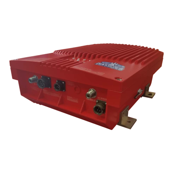
- Page 1 Installation Operating Manual BDA-PS9-37/37-90-C 900MHz Band Bi-Directional Amplifier...
-
Page 2: Table Of Contents
Table of Contents SAFETY OPERATION INSTRUCTIONS ................. 3 OVERVIEW ..........................4 FCC NOTE ..........................4 IC NOTE ............................4 NOTE ............................4 RF EXPOSURE WARNING-FCC ....................4 RF EXPOSURE WARNING- INDUSTRY CANADA .............. 5 GENERAL DESCRIPTION ....................... 5 ELECTRICAL SPECIFICATIONS .................... 6 MECHANICAL SPECIFICATIONS .................. -
Page 3: Safety Operation Instructions
SAFETY OPERATION INSTRUCTIONS BEFORE USE Review this manual and insure that all conditions are compatible with the amplifier's specifications. Safe operation may be impaired if this equipment is not used as intended. GENERAL DESCRIPTION This symbol is marked in the manual and denotes important safety operation instructions. -
Page 4: Overview
BDA-PS9-37/37-90-C provides up to 37 dBm composite power and has up to 85db gain. FCC NOTE This is a Class B device. The product has been tested and found to comply with the Booster requirements per FCC Part 90. -
Page 5: Rf Exposure Warning- Industry Canada
RF EXPOSURE WARNING- INDUSTRY CANADA This system has been evaluated for RF Exposure per RSS-102 and is in compliance with the limits specified by Health Canada Safety Code 6. The 8.5 dbi antenna must be installed so as to provide a minimum separation distance of 87.3 cm (34.37 inches) between the antenna and persons within the area. -
Page 6: Electrical Specifications
ELECTRICAL SPECIFICATIONS Down-Link Frequency Range 935-941 MHz Up-Link Frequency Range 896-902 MHz Pass band Gain @ Min. attenuation Up to 85 dB Variable Step Attenuator Range 2-dB 0-30 dB steps Maximum Input Signal Level -30 dBm Input/Output Impedance 50 Ohms VSWR (Input/Output) <1.5: 1 Power Supply @ 37dbm unit... - Page 7 Optional Battery Back-Up Configuration 15 Amp 12 Volt 12 Volt Lead- Lead- Acid Acid Battery Battery Battery Figure 2: Optional Battery Back-Up Configuration Typical DC Recommend Battery Battery Output Composite Current Draw Rated Capacity Back-Up Time Power @24VDC (20 Hour Rate) [Hours] [Amp Hours] 17.75...
-
Page 8: Mechanical Outline
Note: We do not guarantee specifications under Battery Back-Up power. MECHANICAL OUTLINE P a g e... -
Page 9: Connections
Figure 3: Mechanical Outline CONNECTIONS The RF connections are made via two “N-type” female connectors. The RF connector labeled “BASE” must be connected to the antenna pointing towards the base station. The RF connection labeled “MOBILE” must be connected to the antenna / passive DAS facing the area to be covered by the BDA. -
Page 10: Available, Optional Features
BDA ) • Visual Alarms All G-Wave systems include local visual alarms as a standard. Local visual alarms are LED lights located in the unit that indicate various failures. For a list of corresponding alarms, please see Variable Gain Adjustment and LED Indicators. -
Page 11: Alarm Conditions
AVAILBLE, OPTIONAL FEATURES (Cont.) • DC28 Powered DC Only @ + 28 VDC • LGHT Lightning Protection on UL/DL Ports • RED - Red Enclosure to signify equipment is for public safety. Please verify your local requirements. • ACSP AC Surge Protection and DC Line Conditioning (Required if powered by generator) •... -
Page 12: Variable Gain Adjustment And Led Indicators
Relay Shown in Non-Alarm VARIABLE GAIN ADJUSTMENT AND LED INDICATORS • AC Power LED - Illuminates when the AC voltage is supplied, the unit is ON, and the AC/DC power supply is operating. • DL ALC LED - Illuminates when DL composite power reaches the ALC set •... -
Page 13: Installation
Figure 5: External LED Indication and Manual Gain Attenuation Access INSTALLATION DO NOT APPLY A.C. POWER TO THE UNIT UNTIL CABLES ARE CONNECTED TO BOTH PORTS OF THE BDA AND THE ANTENNAS. Set the BDA on the floor or mount on a wall (where applicable). Using appropriate screws and anchors, attach the BDA to the wall at the four mounting holes on the side flanges. -
Page 14: Operation
Verify the downlink in-building signal strength and the uplink signal strength at donor antenna meets requirements. Reduce the gain if needed (increase attenuation). Note: Operation of BDA-PS9-37/37-90-C at maximum gain with greater than -30 dBm average power incidents on the MOBILE or BASE ports could cause damage to the BDA. -
Page 15: Diagnostics Guide
DIAGNOSTICS GUIDE The BDA provides long term, care-free operation and requires no periodic maintenance. There are no user-serviceable components inside the BDA. This section covers possible problems that may be related to the installation or operating environment. Gain Reduction Possible causes: Defective RF cables and RF connections to antennas, damaged antenna or Leaky cable Occasional Drop-out of some Channels Possible causes: One channel with very strong power dominates the RF output of the... - Page 16 APPENDIX 1 26-Pin Connector Mobile Antenna Failure contacts are not standard in the O26 pin- out and must be requested at time of order to be included. Conditions for Donor Alarm (26-pin) This functionality applies only for a Donor antenna with a DC short.
- Page 17 APPENDIX 1 O26 Alarm Block Diagram 17 | P a g e...
- Page 18 APPENDIX 2 The horizontal I and vertical I space antenna isolation for a scenario as in Figure 6 can be dh ∙ f [ db ] = 22 + 20log � computed analytically, using the following equations: � − GTx − GRx 3 ∙...
Need help?
Do you have a question about the BDA-PS9-37/37-90-C and is the answer not in the manual?
Questions and answers