
Related Manuals for G-Wave BDA-1XXX-.X/.XW-XX-AX Series


Summary of Contents for G-Wave BDA-1XXX-.X/.XW-XX-AX Series
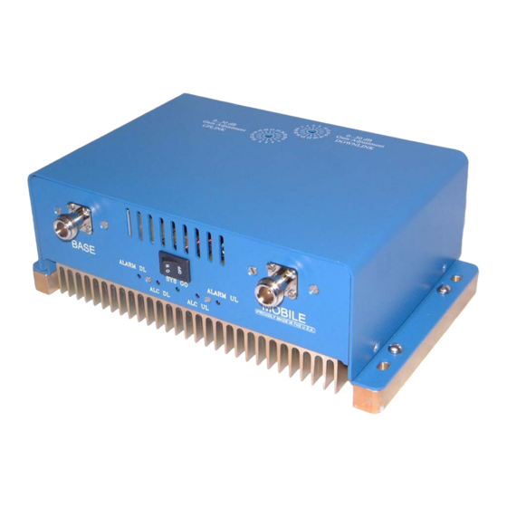
- Page 1 INSTALLATION OPERATING MANUAL BDA-1XXX-.X/.XW-XX-AX MINI-BI-Directional Amplifier...
-
Page 2: Table Of Contents
TABLE OF CONTENTS PARAGRAPH PAGE NO Mini-BDA OVERVIEW Mini-BDA BLOCK DIAGRAM DESCRIPTION Mini-BDA OPTIONS Mini-BDA BLOCK DIAGRAM DRAWING (Figure 1) ELECTRICAL SPECIFICATIONS FREQUENCY RANGES (Table 1) SYSTEM SPECIFICATIONS (Table 2) MECHANICAL CONNECTIONS ENVIRONMENTAL CONDITIONS Mini-BDA CONNECTIONS MECHANICAL OUTLINE DRAWING (Figure 3 & 3a) RF EXPOSURE WARNING Mini-BDA INSTALLATION Mini-BDA OPERATION... -
Page 3: Mini-Bda Overview
Mini-BDA OVERVIEW: The Mini-BDA assembly extends the coverage area of radio communications in buildings and RF shielded environments. The Mini-BDA has dual RF paths to extend coverage in two distinct frequency bands. The unit features low noise figure and wide dynamic range. It is based on a duplexed path configuration with sharp out of band attenuation allowing improved isolation between the receiving and transmitting paths. -
Page 4: Mini-Bda Block Diagram Drawing (Figure 1)
Figure 1 Mini-BDA BLOCK DIAGRAM Up-Link Diplexer - has low pass band insertion loss and high selectivity Down-Link Pre-amp - is a low noise amplifier that drives the Down-Link MPA and offers 38dB Gain Down-Link MPA – is a medium power amplifier with an ALC circuit which offers 40dB Gain. (High power amplifier with an ALC circuit which offers 40dB Gain for 1 &... -
Page 5: Electrical Specifications
ELECTRICAL SPECIFICATIONS: Frequency Range : See Table 1 Pass band Gain @ min attenuation : See Table 2 Nominal Channel Bandwidth : 25.3 MHz typical Variable Step Attenuator Range : 0-30 dB (2-dB steps) Pass band Ripple : ±1.5 dB typical °... -
Page 6: Frequency Ranges (Table 1)
Table 1 Frequency Downlink Uplink Band Frequency Frequency Ranges Ranges PCS A 1930-1945 MHz 1850-1865 MHz PCS B 1950-1965 MHz 1870-1885 MHz PCS C 1975-1990 MHz 1895-1910 MHz PCS D 1945-1950 MHz 1865-1870 MHz PCS E 1965-1970 MHz 1885-1890 MHz PCS F 1970-1975 MHz 1890-1895 MHz... -
Page 7: Mechanical Connections
MECHANICAL SPECIFICATIONS: Size : 8.75 x 6.20 x 3.0 inch : (222.3 x 157.5 x 76.2 mm) RF Connectors : N-type Female Weight : 2.0 Lbs. (4.4 kg.) approx. ENVIRONMENTAL CONDITIONS: The unit is designed for indoor applications: Operating temperature: - 20°C to + 50°C Storage temperature: - 50°C to + 90°C Mini-BDA CONNECTIONS The Mini-BDA is powered by a +15 VDC/1.67 Amp Wall Plug-In AC adapter with a... -
Page 8: Mechanical Outline Drawing (Figure 3 & 3A)
Figure 3 Mini-BDA Mechanical Outline 0...30 dB Gain Adjustment DOWNLINK 0...30 dB Gain Adjustment UPLINK 2PGN IN BUILDING REPEATER (Heat Sink included with 1 & 2 Watt Models) Downlink Alarm Uplink Alarm Figure 3a (Relay Shown in Conditions for Optional Alarm Non-Alarm Condition) The alarm monitors current of both uplink and downlink amplifiers. -
Page 9: Rf Exposure Warning
RF EXPOSURE WARNING In order to satisfy the FCC RF exposure requirements, the Mini-BDA/antenna installation must comply with the following: The outdoor antenna (Yagi type or similar directional antenna) must be installed so as to provide a minimum separation distance of 0.3 meters (30 cm) between the antenna and persons within the area. -
Page 10: Mini-Bda Installation
Mini-BDA INSTALLATION DO NOT APPLY A.C. POWER TO THE Mini-BDA UNTIL CABLES ARE CONNECTED TO BOTH PORTS OF THE Mini-BDA AND THE ANTENNAS. 1. Mount the Mini-BDA on the wall with the RF connectors pointing DOWN. Using appropriate screws and anchors, attach the Mini-BDA to the wall at the four mounting holes on the side flanges. -
Page 11: Mini-Bda Operation
Mini-BDA OPERATION Refer to figure 3 and 4 for adjustment access location and label. Variable Step Attenuator Mini-BDA gain can be reduced by up to 30 dB in 2 dB steps using the variable step attenuator. Gain adjustment is made with rotary switches accessible from the top of the Mini-BDA enclosure (See Figure 4). -
Page 12: Mechanical Outline- Adjustment (Figure 4)
Figure 4 Adjustment Access and Label Page 12... -
Page 13: Diagnostics Guide
DIAGNOSTICS GUIDE The Mini-BDA provides long term, care-free operation and requires no periodic maintenance. There are no user-serviceable components inside the Mini-BDA. This section covers possible problems that may be related to the installation or operating environment. a. Gain Reduction Possible causes: Bad RF cables and RF connections to antennas, Damaged antennas.
Need help?
Do you have a question about the BDA-1XXX-.X/.XW-XX-AX Series and is the answer not in the manual?
Questions and answers