
Related Manuals for G-Wave BDA-SMR/N-37


Summary of Contents for G-Wave BDA-SMR/N-37
- Page 1 Installation Operating Manual BDA-SMR/N-37/37-90-AB SMR/N Bi-Directional Amplifier...
-
Page 2: Table Of Contents
Table of Contents SAFETY OPERATION INSTRUCTIONS ................. 3 OVERVIEW ..........................4 FCC NOTE ..........................4 IC NOTE ............................4 NOTE ............................4 RF EXPOSURE WARNING-FCC ....................4 RF EXPOSURE WARNING- INDUSTRY CANADA .............. 4 ELECTRICAL SPECIFICATIONS .................... 6 MECHANICAL SPECIFICATIONS ..................6 ENVIRONMENTAL CONDITIONS .................. -
Page 3: Safety Operation Instructions
SAFETY OPERATION INSTRUCTIONS BEFORE USE Review this manual and insure that all conditions are compatible with the amplifier's specifications. Safe operation may be impaired if this equipment is not used as intended. GENERAL DESCRIPTION This symbol is marked in the manual and denotes important safety operation instructions. -
Page 4: Overview
OVERVIEW The BDA assembly enhances the coverage area of radio communications in buildings and RF shielded environments. The BDA has dual RF paths (Down-Link / Up-Link) to improve coverage in two distinct frequency bands. The unit features low noise figure and wide dynamic range. It is based on a dual duplexed path configuration with sharp out of band attenuation allowing improved isolation between the receiving and transmitting paths. - Page 5 Refer to Figure 1 for the BLOCK DIAGRAM DESCRIPTION following discussion. The downlink path of BDA receives RF signals from the base station, amplifies the signal and transmits the signal, without changing the frequency, into a Distributed Antenna System at the direction of the mobiles.
-
Page 6: Electrical Specifications
ELECTRICAL SPECIFICATIONS Down-Link Frequency Range 862 -869 MHz Up-Link Frequency Range 817 - 824 MHz Pass band Gain @ Min. attenuation Up to 92 dB Variable Step Attenuator Range 2-dB 0-30 dB steps Maximum Input Signal Level -30 dBm Input/Output Impedance 50 Ohms VSWR (Input/Output) <1.5: 1... - Page 7 Optional Battery Back-Up Configuration 15 Amp Fuse 12 Volt 12 Volt Lead-Acid Lead-Acid 15 Amp Battery Battery Battery of Figure 2: Optional Battery Back-Up Configuration Typical DC Recommend Current Battery Battery Rated OutputComposite Draw Back-Up Time Capacity Power @24VDC [Hours] (20 Hour Rate) [Amp Hours] 17.75...
-
Page 8: Mechanical Outline
MECHANICAL OUTLINE Figure 3: Mechanical Outline P a g e... -
Page 9: Connections
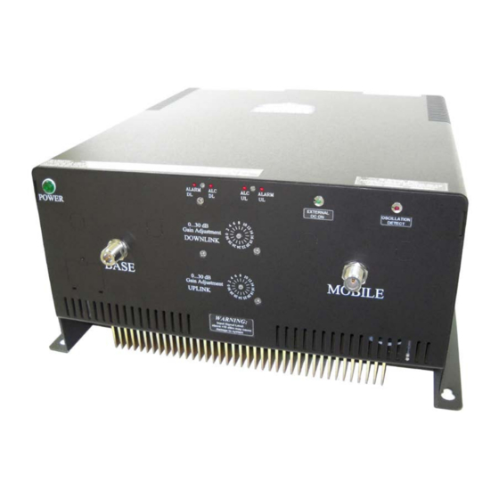
CONNECTIONS The RF connections are made via two “N-type” female connectors. The RF connector labeled “BASE” must be connected to the antenna pointing towards the base station. The RF connection labeled “MOBILE” must be connected to the antenna / passive DAS facing the area to be covered by the BDA. - Page 10 CONNECTIONS (Cont.) Figure 4b: Back Panel Connections 10 | P a g e...
-
Page 11: Available, Optional Features
) • Visual Alarms All G-Wave systems include local visual alarms as a standard. Local visual alarms are LED lights located on the unit that indicate various failures. For a list of corresponding alarms, please see Variable Gain Adjustment and LED Indicators. -
Page 12: Alarm Conditions
AVAILBLE, OPTIONAL FEATURES (Cont.) • DC28 Powered DC Only @ + 28 VDC • LGHT Lightning Protection on UL/DL Ports • RED - Red Enclosure to signify equipment is for public safety. Please verify your local requirements. • ACSP AC Surge Protection and DC Line Conditioning (Required if powered by generator) ALARM CONDITIONS The alarm monitors the current of both the uplink and downlink amplifiers. -
Page 13: Variable Gain Adjustment And Led Indicators
VARIABLE GAIN ADJUSTMENT AND LED INDICATORS • AC Power LED - Illuminates when the AC voltage is supplied, the unit is ON, and the AC/DC power supply is operating. • DL ALC LED - Illuminates when DL composite power reaches the ALC set •... -
Page 14: Installation
INSTALLATION DO NOT APPLY A.C. POWER TO THE UNIT UNTIL CABLES ARE CONNECTED TO BOTH PORTS OF THE BDA AND THE ANTENNAS. Set the BDA on the floor or mount on a wall (where applicable). Using appropriate screws and anchors, attach the BDA to the wall at the four mounting holes on the side flanges. (Special version not shown in this manual). -
Page 15: Operation
OPERATION Refer to Figure 4 & 5 for adjustment access location, connectors and labels Variable Step Attenuator BDA gain that indicated in the spec can be reduced by up to 30 dB in 2 dB steps using the variable step attenuator. Gain adjustment is made with rotary switches located on the front panel of the BDA enclosure. -
Page 16: Diagnostics Guide
DIAGNOSTICS GUIDE The BDA provides long term, care-free operation and requires no periodic maintenance. There are no user-serviceable components inside the BDA. This section covers possible problems that may be related to the installation or operating environment. Gain Reduction Possible causes: Defective RF cables and RF connections to antennas, damaged antenna or Leaky cable Occasional Drop-out of some Channels Possible causes: One channel with very strong power dominates the RF output of the... - Page 17 APPENDIX 1 26-Pin Connector Conditions for Donor Alarm (26-pin) This functionality applies only for a Donor antenna with a DC short. Alarm monitors the connection of the BDA to the donor antenna. An alarm condition will occur if there is a disconnect at the donor antenna. Uplink and Downlink amplifiers will shut down.
- Page 18 Alarm Block Diagram 18 | P a g e...
- Page 19 APPENDIX 2 The horizontal I and vertical I space antenna isolation for a scenario as in Figure 6 can be dh ∙ f [ db ] = 22 + 20log � computed analytically, using the following equations: � − GTx − GRx 3 ∙...
Need help?
Do you have a question about the BDA-SMR/N-37 and is the answer not in the manual?
Questions and answers