
Related Manuals for Digiever DFS-4200-RM Series


Summary of Contents for Digiever DFS-4200-RM Series
- Page 1 Failover Server Quick Installation Guide DFS-4200-RM Series Version: 1.2.0.6 Information in this document is subject to change without notice. © Copyright 2023, DIGIEVER Corporation. All rights reserved.
-
Page 2: Table Of Contents
Package Contents .................. 5 Hardware Description ................6 Hard Disk Installation ................7 Connection to DIGIEVER Failover Server ..........8 Quick Configuration ................11 Appendix LED Indicators on Front Panel ..............12 LED Indicators at Rear Panel ..............13... -
Page 3: Safety Notice
Quick Installation Guide Thank you for choosing DIGIEVER products. The following quick guide will lead you to complete the installation and configuration of the product. Please read the following description carefully. Safety Notice The following safety precautions will increase the life of the product. -
Page 4: Pre-Installation Notice
Pre-installation Notice Please make sure the following items are prepared for installing DIGIEVER Failover Server. Network connection Computer for configuring the Failover Server 1-4 hard disks Compatibility of hard disk with the Failover Server 1 slotted screwdriver and 1 Philips screwdriver ... - Page 5 Graphics Adapter AGP or PCI-Express, minimum 1024 × 768, 16bit colors, 1G memory or above Note: It is highly recommended to use a graphics adaptor which provides higher than resolutions 1024 x 768 in order to experience the full benefits of the software. Make sure the display DPI setting is set to default at 96DPI ...
-
Page 6: Package Contents
Package Contents Failover Server Power Cord Ethernet Cable Screw Bag Product CD... -
Page 7: Hardware Description
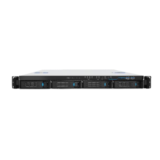
Hardware Description Front View Rear View HDD LED indicator Network LED indicator Power LED indicator One-touch backup button with LED indicator 2 x USB3.2 Gen 1x1 (Front) HDD 1 HDD 2 HDD 3 HDD 4 10. Reset button 11. Digital Input/Digital Output (4-in, 4-out) Max24V, DI_GND, DI-4, DI-3, DI-2, DI-1, OCOM, DO4, DO3, DO2, DO1 12. -
Page 8: Hard Disk Installation
Hard Disk Installation Please follow the steps as illustrated below to install the hardware: Take out the disk tray from Server. Connect the Ethernet cable to the port of 2.5 Gigabit LAN. Install the hard disk in each tray ... -
Page 9: Connection To Digiever Failover Server
Connection to DIGIEVER Failover Server Please insert the product CD-ROM on a PC to install NVR Search. Finally, you can start Quick Configuration on a web page. Install NVR Search for finding Failover Server in the network. ... - Page 10 Connect to the Failover Server 1. Connect to DIGIEVER Failover Server After setting the NVR Search, the user can connect to the monitoring page by the following two options: NVR Search Once you click “Connect” or double click the selected Server list, the web browser will pop up automatically.
- Page 11 2. Enter a user name and password Log in the Failover Server with the default administrator account (user name: admin, password: admin). 3. Download and install NVR-Client.exe, a software application, to execute liveview monitoring and video playback.
-
Page 12: Quick Configuration
Once the five steps of Quick Configuration are complete, you can go Management > Failover section in configuration page to configure Failover settings. For further details of Quick Configuration, please refer to Failover User Manual. After adding NVR to Failover Server, you have successfully installed the DIGIEVER Failover Server. Congratulations! -
Page 13: Appendix
Appendix LED Indicators on Front Panel LED Color & Indicate Status LAN Link is not established Orange LAN Link is established Orange LAN is being accessed blinking Hard disk drive device is not established 1. Hard disk drive is ready to be accessed Green 2. -
Page 14: Led Indicators At Rear Panel
LED Indicators at Rear Panel LED Position LED/State Indicate LAN Link is not established LAN1 Link/Activity Yellow LAN Link is established LAN2 (Right LED) Yellow Blinking LAN activity is occurring 10Mbps connection or no connection LAN1 Speed 100Mbps connection LAN2 (Left LED) Green 1000Mbps connection...
Need help?
Do you have a question about the DFS-4200-RM Series and is the answer not in the manual?
Questions and answers