Digiever SS-7000-RM User Manual
Streaming server
Hide thumbs
Also See for SS-7000-RM:
- Quick installation manual (9 pages) ,
- Quick installation manual (12 pages)

Related Manuals for Digiever SS-7000-RM


Summary of Contents for Digiever SS-7000-RM
- Page 1 Streaming Server User Manual 1.0.0.3 Information in this document is subject to change without notice. © Copyright 2021. All rights reserved.
-
Page 2: Table Of Contents
Table of Contents Chapter 1. Introduction ................4 Hardware Description ................. 4 1.1.1 SS-7000-RM ..................4 LED Indicators Status..................5 1.2.1 SS-7000-RM ..................5 Mirror Display Solution: HDMI/VGA Connection ........7 Chapter 2. Streaming Server Installation ..........8 Remote Client PC System Requirements ..........8 Connect to Streaming Server .............. - Page 3 Quick Configuration .................. 54 3.4.1 System Upgrade on Local Display ..........54 Chapter 4. Use Streaming Server by Remote Client ......55 Liveview ...................... 58 4.1.1 Select View Modes on Liveview Page ........... 59 4.1.2 Main Functions for Liveview ............60 4.1.3 Right Click Functions on Video Window ........
- Page 4 5.2.1 Event & Action Management ............115 5.2.2 E-Mail .................... 119 Network ..................... 121 5.5.1 Network Setup ................121 5.5.2 Network Service ................127 Management ................... 130 5.6.1 User Management ................ 130 5.6.2 Log System ................... 134 5.6.3 Save/Load Configuration ............. 137 5.6.4 UPS Management .................
-
Page 5: Introduction
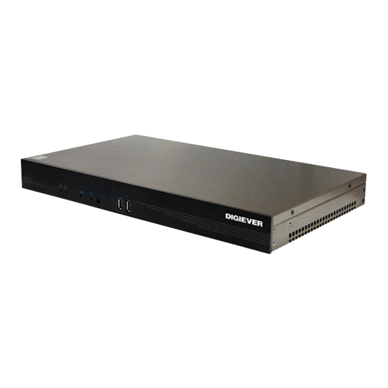
“Package Contents” of “Quick Installation Guide” are included. Before installing the NVR, please read the instructions in the “Quick Installation Guide” to avoid misuse. 1.1 Hardware Description 1.1.1 SS-7000-RM Figure 1-1. Front & Rear View of SS-7000-RM LED indicators: LAN LED indicators: Backup LED indicators: Power Power button Backup USB 2.0 x 1... -
Page 6: Led Indicators Status
1.2 LED Indicators Status 1.2.1 SS-7000-RM Figure 2-7. Front View of SS-7000-RM & RJ-45 Port LED on Front Panel LED Color & Status Indicate LAN Link is not established Orange LAN Link is established Orange blinking LAN is being accessed... - Page 7 Note: Once users press reset button, configuration of Camera Setting, Event & Action Setting, E-Mail Settings, and Server Settings will reset to default. It is advised to backup system configurations. For more information, refer to detail information in user manual 5.6.3 Save/Load Configuration.
-
Page 8: Mirror Display Solution: Hdmi/Vga Connection
1.3 Mirror Display Solution: HDMI/VGA Connection Streaming Server provides HDMI and VGA port for system configuration. Users can connect both of HDMI and VGA at the same time for video output. Mirror display scenario Scenario A: If both monitors are Full HD (1920x1080), those will be shown as Full HD. Scenario B: If both monitors are XGA (1024x768), those will be shown all as XGA. -
Page 9: Streaming Server Installation
Chapter 2. Streaming Server Installation 2.1 Remote Client PC System Requirements The following information is the minimum required specification for remote Windows PC, which users can open a remote browser from the PC to access the Streaming Server on the network. ... - Page 10 Remote Computer Requirement to Enable DG-Decode Powered by Intel GPU technology, Linux NVR server supports GPU hardware acceleration decode for H.265 and H.264 IP camera on remote monitoring and playback to reduce CPU utilization and enhance video fluidity to display multi-channel high-resolution cameras.
-
Page 11: Connect To Streaming Server
2.2 Connect to Streaming Server To begin, please insert the product CD-ROM in a PC to access the Quick Guide, User Manual and install the utilities. As user runs the product CD, the following menu is displayed. 2.2.1 Quick Guide Click “Quick Guide”... - Page 12 When installing EZ Search, Shield Wizard window for EZ Search will pop up. Click “Next” to continue installation. Read the license agreement and click “I accept the terms of the license agreement”. Click “Next” to continue installation.
- Page 13 Select a location of destination and select a folder where the setup can install files. The default location is: C:\Program Files (x86)\NVR\NVR Search. Users can also install EZ Search in other folder by clicking “Change” and select a location as below. Click “OK”...
- Page 14 The window shows that the InstallShield Wizard is installing NVR Search. Please wait until the Wizard completes the installation. The InstallShield has successfully installed NVR Search. Select “Create Desktop Shortcut”/ “Create Quick Launch Shortcut”/ “Create Start Menu Shortcut” and please click “Next” to continue.
- Page 15 The installation is complete. Please click “Launch application when done installing” to execute NVR Search. After finishing the setup, the window of NVR Search will pop up. NVR Search will execute automatically and show NO., Name, IP Address, Mac Address and Model name of connected NVR. Users can click “Search”...
- Page 16 Introduction of NVR Search NVR Search provides three kinds of toolbars for users: File You can click “Exit” to leave NVR Search and close the window. Setting Configure UPnP and Network by clicking “Setting” in the top left or in the middle right.
- Page 17 Note: Users will be prompted to enter the login information of NVR before being allowed to change the setting. When accessing the NVR setting, users will be prompted to enter username and password. For the first-time use, the default username and password are admin/admin.
- Page 18 2) Network NVR provides two network settings: DHCP and Static IP.
-
Page 19: Install Upgrade Tool
3. Option Option provides users to change language. 2.2.3 Install Upgrade Tool Click “Upgrade Tool” to upgrade several NVR to the latest firmware version. Please follow the instructions to install and Upgrade Tool will run automatically. When installing Upgrade Tool, Shield Wizard window for Upgrade Tool will pop up. Click “Next”... - Page 20 Read the license agreement and click “I accept the terms of the license agreement”. Click “Next” to continue installation. The window shows that the InstallShield Wizard is installing Upgrade Tool. Please wait until the Wizard completes the installation.
- Page 21 The installation is completed. Please click “Launch application when done installing” to execute Upgrade Tool. And click “Finish”. After finishing the setup, the window of NVR Search will pop up. Upgrade Tool shows No., Device Name, Model Name, IP Address, Current Firmware and Password of the connected devices.
- Page 22 devices. (Please use administers’ password.) If the device password is NOT the default password, user can manually enter the password in the password bar and then press “Enter” on the keyboard. After typing the correct password, the password bar will show “Successful” and current firmware will show automatically.
- Page 23 If the password is not correct, the password bar will show “Failed”. Select the devices at the left column to upgrade firmware. Users can click “Select All” or “Cancel All” button to select or cancel all the devices.
- Page 24 Click “Browse” to upload firmware file to upgrade the devices. A window will pop up to ask for the folder to upload the firmware. Select the file and click “Open”.
- Page 25 After selecting the file, firmware file path will show. Please click “Upgrade” button. A window will pop up to make sure the execution . Please click “Yes” button. The window will show the upgrade process of each device.
- Page 26 After upgrading successfully, the progress column will show “Successful”. After upgrade successfully, user can double click the device to log in NVR.
-
Page 27: Install Nvr Decoder
If the upgrading is not successful, the progress column will show the message. 2.2.4 Install NVR Decoder Click “Install S-NVR Decoder” to install decoder and follow the instructions to setup. Install Shield Wizard window will pop up and please click “Next” to continue installation. - Page 28 Read license agreement and click “I accept the terms of the license agreement.” Click “Next” to continue installation. The installation Wizard is installing NVR Decoder.
- Page 29 The installation is complete. Please click “Finish” to close the window.
-
Page 30: Nvrplayer
2.2.5 NVRPlayer NVRPlayer allows users to view the recorded videos exported from NVR. It is a portable tool with no need to install on PC. NVRPlayer can play multi-channel videos via playlist which is exported from instant export. Click “Open File” button to select a video or a playlist to play videos. For more information about export videos to PC, please refer to 4.3.7 Export. - Page 31 NVRPlayer will display playback video time on the top-left corner for time reference. Right-click on the video to execute 360-degree ImmerVision dewarp. Users can move “Time Bar” to desired time when playing recorded video.
- Page 32 Feature introduction Frame by Frame Playback Please click “Pause” button and click “Next Frame” or “Previous Frame” to find the desired video precisey. Snapshot Please click “Snapshot” button to take a photo to your PC.
-
Page 33: Install Nvr Check
2.2.6 Install NVR Check Click “Install NVR Check” to open the folder and double-click on user manual file to read. Install Shield Wizard window will pop up and please click “Next” to continue installation. Read license agreement and click “I accept the terms of the license agreement.” Click “Next”... - Page 34 Select a folder where the setup can install files. The default location is: C:\Program Files (x86)\NVR\NVR Check. Users can also install NVR Check in other folder by clicking “Change” and select a location as below. Once a folder is selected, please click “OK” to continue installation.
- Page 35 The window shows that the InstallShield Wizard is installing NVR Check. Please wait until the Wizard completes the installation. The InstallShield has successfully installed NVR Check. Select “Create Desktop Shortcut”/ “Create Quick Launch Shortcut”/ “Create Start Menu Shortcut” and please click “Next” to continue.
- Page 36 The installation is complete. Please click “Launch application when done installing” to execute NVR Check. After finishing the setup, the window of NVR Check will pop up. Introduction of NVR Check While NVR is recording video and snapshot files, the digital watermark will be embedded automatically in the images.
-
Page 37: User Manual
If the recording file is originated from NVR, NVRCheck will show “No error occur.” If the recording file has been changed, NVRCheck will show “There is an error in the video file.” To know more information, please ask the manufacturer by providing detailed information in “Detail”... - Page 38 2) IE browser Log in to the system by entering its IP address in IE browser. 2. Enter username and password: For first-time use, the default username and password are “admin/admin.” 3. Select the languages for the UI. 4. Download and install NVR-Client.exe, a software application, to execute liveview monitoring and video playback.
-
Page 39: Quick Configuration
2.3 Quick Configuration After users log in NVR and install the ActiveX control, the system will direct you to set Quick Configuration in five main steps. Follow the instructions of the Overview of wizard to complete system setup. 2.3.1 Start System will lead you to “Start”... -
Page 40: Network Settings
2.3.2 Network Settings Please select “Network Settings” from the drop-down menu of Configuration Utility to begin. Users need to adjust the settings in the Network Setup page in order to let NVR work properly within network. There are 2 methods to configure IP address 1. -
Page 41: Server Settings
To assign a static IP address to the NVR: 1. Select “Specify an IP address” 2. Enter the IP address, Subnet Mask, Default Gateway IP Address and DNS server address. 3. If IP Address is changed, user needs to log out NVR and login in again. Click “Next”... -
Page 42: Date & Time
2.3.4 Date & Time Please select “Date & Time” from the drop-down menu of Configuration Utility to begin. Manual setting Use the drop-down list and configure the time manually. Select the Year, Month, Date and Time. Time setting will be effective when you click “Next.” Time Zone: Synchronize with an Internet time server automatically. - Page 43 Configure the time and date by verifying and adjusting current local time and daylight saving to avoid the following errors: Incorrect display time for playback videos. Inconsistent display time of event logs and when they actually occur. Please enter the hostname of a valid NTP server to synchronize the server time with an Internet time server.
-
Page 44: Camera Settings
2.3.5 Camera Settings NVR provides 2 options to add new cameras: Detect and UPnP Search/ONVIF Search [Method1] Detect: In this option, users are asked to enter IP Address. Check correct username and password. Then, click “Apply” button to start adding camera. After clicking “Apply”... - Page 45 After successfully adding cameras, NVR will display camera information in camera list. To delete camera, please click the check box and click “Delete” button. You can delete all cameras by clicking “All” check box. A window will pop up to ensure the action. To delete the camera, click “OK”...
- Page 46 [Method2] UPnP Search/ONVIF Search: Click “UPnPSearch” to find out UPnP devices within the LAN. Please make sure IP camera supports UPnP Search function. Please go to IP Camera web page to enable UPnP search function. For cameras that cannot be found via UPnP search, please use ONVIF Search. Via ONVIF search button, users can efficiently find and add unintegrated ONVIF cameras to NVR.
- Page 47 Note: Users can click “All” to add cameras in Added column. Note: The Added column will show two numbers to display the total channels of the NVR and the channel numbers that has been already added in the NVR. Please check select cameras in Group add page. Then, Click “Add All” button to start adding cameras.
- Page 48 You may click “Cancel” button to stop camera adding progress. Status column in camera list will display “Successful” when cameras are successfully added in NVR. Please click “Go to Camera Settings” button to check all camera information camera list that is successfully added in NVR.
- Page 49 The Description of Camera Settings: (1) Memorize modified username and password: NVR can memorize username and password which is modified by users after users click “Apply” button. Then, the default username and password of that vendor will be replaced by the modified one. Next time when users add new camera of the specific vendor, username and password will be automatically filled in by new modified one.
- Page 50 Optimization by NVR ① By selecting this option, NVR will optimize camera settings to execute the best surveillance performance. Settings from camera ② If users have already set up camera settings from camera webpage, NVR can adopt camera setting by selecting “Setting from Camera.” This option can largely save users’...
- Page 51 (5) Generic RTSP/ Generic MJPEG (for Detect method only) For cameras without native integration, NVR allows users to add cameras via Generic RTSP (H.264) and Generic MJPEG to receive the video streaming from IP camera. The streaming will be applied to monitoring, recording and playback. Please select Generic RTSP or Generic MJPEG on brand column.
-
Page 52: Finish
If Generic RTSP is selected, RTSP port should be filled out too. Click “Apply” button to save setting. The most correct URLs should be provided from each camera vendors. Users may also refer to websites https://www.soleratec.com/rtsp/ http://www.ispyconnect.com/sources.aspx 2.3.6 Finish Please select “Finish” from the drop-down menu of Configuration Utility to begin. Once five steps of Quick Configuration are completed, the window will show the completed status. -
Page 53: Use Streaming Server By Local Display
Chapter 3. Use Streaming Server by Local Display Server can be connected to a monitor via HDMI/VGA port to execute quick configuration and display live view. To start local display, please check the steps below: 1. Please install at least one hard disk drive in your server. 2. -
Page 54: Virtual Keyboard
1.1.1 Virtual Keyboard Users can choose to use USB keyboard for typing in local display of NVR, or fill out columns with virtual keyboard. The virtual keyboard in local display can be enabled from the right side of each column. There are 3 types of virtual keyboard can be chosen, including Upper case, Lower case and Symbols. -
Page 55: Quick Configuration
3.2 Quick Configuration After you log in local display of NVR, the system will direct you to set Quick Configuration in five main steps. Follow the instructions of the Overview of wizard to complete the system setup. For further information, please refer to chapter 2.3 Quick Configuration. -
Page 56: Use Streaming Server By Remote Client
Chapter 4. Use Streaming Server by Remote Client Users can monitor the network camera and view playback from NVR via NVR-Client. Via web browsers (IE/ Chrome/ Firefox/ Opera browser in Windows), users can configure server’s settings. To execute liveview monitoring or video playback, it is necessary to install surveillance software application, NVR-Client. - Page 57 Read license agreement and click “I accept the terms of the license agreement.” Click “Next” to continue installation. Select a folder where the setup can install files. The default location is: C:\Program Files (x86)\NVR. Users can also install NVR-Client in other folder by clicking “Change” as below.
- Page 58 Once a folder is selected, please click “OK” to continue installation. The window shows that the InstallShield Wizard is installing NVR-Client. Please wait until the Wizard completes the installation. The InstallShield has successfully installed NVR-Client. Click “Finish” to close the InstallShield.
-
Page 59: Liveview
Liveview After Quick Configuration is complete, the server will guide you to live view. Users can view live video stream from IP camera via network and monitor the instantaneous view remotely. Liveview displays the video according to the camera list which has been configured in camera settings of Quick Configuration. -
Page 60: Select View Modes On Liveview Page
4.1.1 Select View Modes on Liveview Page On top right of live view, users can select four view modes. Mode Description Liveview: Click “Liveview” to control the monitoring instantaneously. Playback: Click “Playback” to play and to export the recorded video files storage in NVR. Configuration: Click “Configuration”... -
Page 61: Main Functions For Liveview
4.1.2 Main Functions for Liveview 1. Multiplex window Multiplex window offers 2 modes. Click to switch the mode. (1) Camera list Camera list will be shown in default. To set up mini-CMS, please click below icon: 錯誤! 找不到參照來源。 Please refer to 4.1.6 for detail information. - Page 62 White word with black Video compression format, such background as H.265/ H.264/ M-JPEG/ at the top middle corner MPEG-4/ MxPEG Yellow triangle with an Event is triggered exclamation mark Gray speaker Support Audio Green speaker Audio on (channel is selected) Gray microphone Support microphone Microphone on...
- Page 63 There are three functions for snapshot: Clipboard: To copy image to computer’s temporary memory. User can paste image to graphics painting program such as Paint for advanced editing. Save: To save image to desired path. Cancel: To cancel snapshot. Digital zoom in/ out: Select a channel to enable digital zoom function Drop: Drop the camera from monitoring.
- Page 64 9 screen 12 screen 16 screen 20 screen 2(1x2/2x1)/3/5/6/25/30/32/36/42/49/56/64 screen 5+1 screen 8 screen 12+1 screem 10 screen Full Screen Sequential mode Click to choose the page of liveview...
- Page 65 6. Camera Information Server will show Camera name, IP address, bit rate and hardware decode status of the selected camera channel. Status Description Enable: H.265/H.264 hardware decode is enabled Disable: H.265/H.264 hardware decode is disabled Note: Users can individually enable and disable hardware acceleration decode on liveview and playback’s setting page.
- Page 66 will move to the position that user selects. Optical zoom in/ out: If camera supports PTZ control, users can adjust PTZ camera to zoom out or zoom in. Focus near / far: If camera supports PTZ control, users can adjust the focus of the PTZ camera to focus near or focus far.
- Page 67 Modify PTZ auto cruising ① Select a Preset Point No. ② Change Interval and Moving Speed Click “Update” button ③ Delete PTZ auto cruising ① Select a Preset Point No. Click “Delete” button ② Define the maximum of auto cruising ①...
- Page 68 Event log list will show camera network disconnected NVR events (external event & camera events) when the cameras are added from NVR. If users want to check streaming server’s events, please go to streaming server’s configuration page. (Management > Log System > System Log & Hardware Log) Enable Alert sound If users enable the function, the PC will sound the alarm to notify users when an event is triggered.
- Page 69 9. Option: 1) General: ① Automatically reorder Liveview windows To rearrange video in order without blank grid after users drop video from live-view. ② Resize all video sizes at the same time Only a right click on the video, users can set "all" video size either in original size or fit size.
- Page 70 ③ Highlight video window when event is triggered The option of “Highlight video window when event is triggered” is a warning frame which will pop out on the channel when an event is detected. When the motion event is awarded, user can simply click on the channel with mouse, the warning frame will be stopped.
- Page 71 __seconds later close the pop-out windows. (5-180) Users can select an optional feature to make the pop-out window automatically close after users assigned seconds. (Default is 10 seconds) All cameras in the NVR will have event pop-out window. If user enables event pop-out window for all cameras, all channels in the Server’s camera list will pop-out a video when an event is triggered.
- Page 72 2) Multi-Server: Users can save the camera list of multi-server on live-view page. 3) Sequential Mode Setting: Click sequential interval to set the numbers of user-defined seconds for sequential mode. 4) Joystick: Users are able to manipulate PTZ camera with USB joystick. Choose the joystick column and select joystick model then press “Apply”...
- Page 73 Joystick can work on PTZ cameras as the status bar is with PTZ icon. 5) OSD Setting: Select Server, Camera Name, Time Zone, and Time to show on-screen display information on liveview and snapshot. Set up Size, Position, and Color. Bmp and jpg format are supported for snapshot.
-
Page 74: Right Click Functions On Video Window
4.1.3 Right Click Functions on Video Window 1. Video Size: Original or Fit 2. Streaming change: To exchange the streaming resource. (1) Exchange Streaming The Server allows users to setup the dual streaming configurations in cameras parameters page if cameras support dual stream. It is suggested stream 1 is set for higher resolution and stream 2 for lower, which helps users to choose the proper streaming in live view with intuitive control. - Page 75 (2) Enable Optimization Streaming type will be adjusted automatically for different display modes. When users select the display mode with more than 16ch, NVR will automatically change to stream2 for smooth real time viewing experiences. 1/3/4/5+1/8/9/10/12/12+1-ch display mode: ① liveview image automatically show the main stream(stream1) 16/20/25/30/36/42/49/56/64-ch display mode: ②...
- Page 76 Select 5+1 or 7+1 display mode ① Define the areas of interest ② 10. Panomorph: To view the best image quality by dewarping engine. Note: NVR supports IP cameras equipped with Immervision’s Lens and VIVOTEK dewarping engine now. (1) Choose dewarp type: (2) Choose mounting type:...
-
Page 77: Zooming With Mouse Scroll
(3) Choose display mode: 4.1.4 Zooming with Mouse scroll In addition to digital zoom in/out button, users can use mouse scroll to prevent potential crisis in live-view monitoring. Note: For PTZ cameras, zooming with mouse in live-view is adopted optical zoom in/out. -
Page 78: Two-Way Audio
4.1.5 Two-way Audio Two-way audio allows user to remotely communicate via PC and IP cameras, which provides more flexibility in diverse surveillance applications. Applications: (1) Via speaker, users can hear sounds captured from remote camera sites to have the latest update. (2) Via microphone, users can reply it back to remote camera sites. -
Page 79: Multi-Layer Dynamic E-Map
1.2 Multi-layer Dynamic E-Map The Server provides multi-layer E-Map feature on liveview monitoring as a quick navigation to indicate the physical location of cameras. Users can drag and drop camera icons to multi-layer E-Maps and enable pop-out event window to receive the latest event situation once event occurs. - Page 80 Icon Description Pin to Fasten: To display and fasten the panel. Pin to Hide: To hide the panel to the edge of the window. Click the panel name to display the panel when needed. Delete: To close the panel.
- Page 81 (3) Settings: to enable or disable automatically pop-up event window. Please refer to 1.2.4 Double-click to Pop-out Video Window (4) Users can have pop-out video window by two methods: (1) Double-click camera icon on map (2) Double-click camera name on device panel For (1) Double-click camera icon on map, the pop-out window will show below functions for operation.
- Page 82 (1) For Double-click camera icon on map: The adjusted size will be saved when the pop-out window is closed. Once E-map window is closed, the size of pop-out window will be reset to default size. (2) For Double-click camera name on device panel: The adjusted size will be reset when the pop-out window is closed.
-
Page 83: Add Or Delete Multi-Layer E-Maps
Enable/ Disable Automatically Pop-up Event Window for more information. Introduction of icons Icon Description Add Map: Add an E-Map Delete Map: Delete an E-Map Available Camera: Camera in device panel is available to drag to map. Camera on Map: Camera in device panel is unable to drag to map since the camera has already added to one of maps. - Page 84 (2) Right-click on Map Panel: Right-click on the map to build sub-layer of map. 2. Zoom in / out the E-Map To zoom in or zoom out the E-Map, users can use the mouse scroll to enlarge or reduce the view of E-Map. 3.
-
Page 85: Deploy Cameras
(2) Right-click on Map Panel: Right-click on one of the map to delete the map. 1.2.3 Deploy Cameras 1. Add and delete camera on the map (1) Add a camera: Please drag and drop the camera icons in device list to the map to indicate camera location. -
Page 86: Double-Click To Pop-Out Video Window
2. Rotate camera direction Please right click on the camera icon to modify camera direction. 1.2.4 Double-click to Pop-out Video Window Users can have pop-out video window by two methods: (1) Double-click camera icon on map (2) Double-click camera name on device panel... - Page 87 For (1) Double-click camera icon on map, the pop-out window will show below functions for operation. The size of pop-out large video window is adjustable. (1) For Double-click camera icon on map:...
- Page 88 The adjusted size will be saved when the pop-out window is closed. Once E-map window is closed, the size of pop-out window will be reset to default size. (2) For Double-click camera name on device panel: The adjusted size will be reset when the pop-out window is closed.
-
Page 89: Enable/ Disable Automatically Pop-Up Event Window
1.2.5 Enable/ Disable Automatically Pop-up Event Window When a motion is triggered from IP camera on the map, a window will pop out to notify users and to display recording video. To enable or disable automatically pop-up event window on E-Map, please click the option. Note: The maximum of pop-out event window is 4. -
Page 90: Event Log History
1.2.6 Event Log History Event log history offers a detailed and latest list of event history in event panel to make users easily control event situation. The event panel includes Server Name, Date & Time, Camera Name, Camera No. and Description (Camera Connected, Camera Disconnected or Motion Detection.) -
Page 91: Playback
1.3 Playback Playback allows users to retrieve up to 3-day recorded videos of cameras that are added via NVR. The Server offers synchronized playback up to 16 cameras and easy steps to help users sort through the recorded videos quickly. Playback video can be viewed in full screen;... - Page 92 Note: OSD’s default setting is 20-pt font in orange color. Enable DG-Decode (GPU hardware acceleration decode) Enable DG-Decode to leverage Intel GPU resource to playback multi-channel high-resolution cameras. The function can reduce CPU utilization and enhance video fluidity. Note: DG-Decode is enabled in default when your PC’s CPU specification is detected as supported.
- Page 93 2. Select date and time Please select the date to search recorded videos. The date marked in blue background and white words has recorded video. If there is an event recording in the specific date, the date will be remarked as blue with red stripe aside.
- Page 94 3. Select recording type Users can select five types of video file which is also displayed in Time table. These five types of video file are distinguished from different colors in time table: Normal(Gray), Event(Red), Video Clip(Yellow), Recovery(Blue), Time overlap(Green) Failover(Light Blue).
- Page 95 Frame by Frame Playback 1. Follow above four steps to playback 2. Click “Pause” button 3. Click “Previous frame” or “Next frame” button...
-
Page 96: Time-Divided Search
1.3.2 Time-divided Search Based on display mode (2x2, 3x3, 3x4), the Server will divide a video into many snapshots and display the first frame of that period of time on each channel. Once finding the key moment, users can save the snapshot or export a video (5 minutes) on computer. -
Page 97: Smart Search
Once finding the key moment, users can click “Snapshot” or “Export Video” button to save them on your PC. 1.3.3 Smart Search Smart Search can efficiently save users’ precious time to find out key video moment without wasting extra effort and energy. Smart Search offers five quick search modes: motion detection, foreign object detection, missing object detection, camera tampering detection and lose focus. - Page 98 Introduction of settings: (1) Region of interest: the location for quick detection. Motion detection, foreign object detection and missing object detection are needed to arrange region of interest. (Motion detection has 3 region of interest, and others have one region of interest.) (2) Sensibility: the capability to detect event (3) Interval: the amount of time that the object exists in the region...
-
Page 99: Main Functions On Playback
1.3.4 Main Functions on Playback Display mode The Server supports multi-channel simultaneously playback. You can see the recording time of each channel at the top of each grid. Icon Description Full Screen 1 screen 4 screens 5 screens... - Page 100 9 screens 16 screens Mute control Users can choose whether to play audio when playback videos. The button will change icon appearance while clicking: : Mute : Sound Digital zoom out and digital zoom in The image can also return to previous sizes by clicking the digital zoom out button. The image can be enlarged by clicking digital zoom-in button.
- Page 101 Snapshot Users can save the image of playback by clicking “Snapshot”. Before taking snapshot from NVR, users are recommended to set snapshot path from “Setting.” Sequential snapshot on remote playback Users can have the sequent images from recording video while in playback, which helps users catch the crucial frame in the recording files.
- Page 102 Thumbnail on Playback With thumbnail function on playback, users can move the pointer of the mouse over the footage and the snapshot of the specific time will be shown. It helps users easier to locate the period of time for play the recorded videos. From the thumbnail, users can also read the related information such as date, time and camera name.
- Page 103 c. Choose the display mode...
-
Page 104: Data Search
1.3.5 Data Search Data Search is designed to quickly find out key event and data recorded from NVR. There are four main categories supported for data search: 1. NVR Event: Built-in Digital Input, HTTP-in 2. Camera Event: Connection Lost, Motion Detection, Audio Detection, Cross-line Detection, Temperature Detection, Digital Input, Tampering Detection, Loiter Detection, Foreign Object Detection, Miss Object Detection, Advanced Motion Detection, Human Detection, etc. - Page 105 After the list is shown, users can save the event result by below 3 ways: 1. Export the list (csv file) 2. View and save snapshot 3. Play and save video clip Click “Data Search” button . A window will pop up to start configuration. Select event category, event type, time range and select device(s).
- Page 106 Note: For “camera event” category, camera number in Streaming Server’s camera list will be indicated after its name. Eg. Front Door (No.7) 3. Device IP Address 4. Event Type 5. Car Number: designed for license plate recognition’s keyword search 6. Snapshot: click icon to check event image Note: To save event snapshot, please remember to set up events and enable “Save Snapshot when Event Triggered”...
-
Page 107: Zooming With Mouse Scroll
1.3.6 Zooming with Mouse scroll In addition to digital zoom in/out button, users can use mouse scroll to find out crucial proof in incident site in playback. Zoom in/out: To click on the video window and use mouse scroll to enlarge the image. View enlarged images: To press and hold left mouse button, drag the image to the place that you would like to monitor. -
Page 108: Export
1.3.7 Export Export function allows users to retrieve recorded files from NVR. NVR offers two methods to export recorded videos for different export requirements: Method1. Export video by specifying export start time and end time Method2. Instant export (export videos while playing recoded videos) ... - Page 109 7) Click “OK” button NVR will pop-out a window to ask you if you would like to download NVRPlayer and NVRCheck with video files. NVRPlayer is a portable player to play videos exported from NVR. NVRCheck is the verification tool to verify if the recorded files are originated from NVR.
- Page 110 All videos are completely exported and combined. Note: The export file name is export time(yyyymmdd_hhmmss). Method2. Instant Export Instant export allows users to export maximum 16-channel videos while playing recoded videos on playback interface. A playlist will also be exported to PC in order to precisely record export start time and end time.
- Page 111 5) A window will pop out to display export status. On time table, exporting time period will be highlight in purple color. Note: Please don’t close the playback browser page, while it’s exporting the video files. Otherwise, the exporting video will not be saved on your Note: NVR will also download NVRCheck and NVRPlayer to your PC.
- Page 112 Note. The default folder is named by the time when users click the “Start Export” button. (yyyymmdd_hhmmss) Play exported video by instant export 1) Access the exported file Note. Exported file can be found in “Setting” button on playback 2) Unzip and run NVRPlayer 3) Import Playlist to NVRPlayer by clicking “Open File”...
- Page 113 4) Select cameras, start time and end time. Then, click “Play” button to play videos...
-
Page 114: Configuration
Chapter 5. Configuration In configuration page, users can configure Quick Configuration, IP Camera, Recording & Event, Disk Management, Network Management and System from each drop-down menu. Note: The server will automatically log out from configuration page after idle for 10 minutes. IP Camera 5.1.1 Camera Settings... - Page 115 There are two parts in this section: Camera Parameter and Camera List. Please select a camera or cameras of same camera model in Camera List first. As you click one column turning into blue, please wait and the window below will appear to allow user to configure camera parameter.
- Page 116 After loading camera’s information, users can modify below camera parameter: (1) Camera No. Load Select a desired camera no. to switch camera in NVR’s camera list. (2) Stream 1/ Stream 2 (Recording Stream) Decide one stream as recording stream for video recording between stream 1 and stream 2, if cameras support dual streams.
- Page 117 (6) Video Quality Select either “VBR” (Variable bit rate) or “CBR” (Constant bit rate) to set the video quality. (7) Enable Audio Recording To make audio recording function enable or disable. (8) Enable Mobile Snapshot To make mobile snapshot function enable or disable. Please click “Apply”...
-
Page 118: System/ Camera Status
5.1.3 System/ Camera Status Please select “Camera Status” from the drop-down menu of IP Camera to begin. Camera List shows connection status of recording. -
Page 119: Event
Event “Event & Action Management” allows users to define event setting that manage events and its corresponding action for server and hardware system. Cameras that are added via NVR, users can know the alarm from NVR-Clent’s liveview page. It can strengthen security level during monitoring and recording to notify users when necessary. - Page 120 1. Event types (1) System event: Disconnected (2) System event: UPS Warning UPS Low Power Warning will warn users that UPS is nearly out of power before NVR automatically shutdown to sleep mode. Note: UPS Low Power Warning window won’t pop out while on remote playback page. Note: Please enable this feature and fill in a number to trigger event on configuration page: Management >...
- Page 121 2. Action types (1) Send E-Mail E-Mail Configuration window will pop up as you add “Send E-Mail” to action. But there will be no contactor listed in the configuration at first, please go to add a new contactor in the following section “E-Mail.”...
- Page 122 Sample of Email Notice: (2) Digital Output and Camera Digital Output Buzzer can be enabled up to sound for 60 seconds. Digital Output1 and Digital Output2 can be enabled from 3 second to continuous warning. (3) SMS SMS stands for Short Message Service. Users can be notified by short message service while the event is triggered.
-
Page 123: E-Mail
5.2.2 E-Mail Please select “E-Mail” from the drop-down menu of Event to begin. 1. SMTP Server Server Address: Enter the Server Address of the SMTP server. Sender: Specify sender’s E-Mail in the “Sender” field. Subject: Enter the Subject. ... - Page 124 Contact List will show the information you entered. Please click “Apply” to finish settings. You can click “Send Test Mail” to send the testing mail. Before clicking “Apply” button, you can click “Reset” button to clear current unsaved contact list. You can delete the contactor by clicking “Delete” button.
-
Page 125: Network
Network 5.5.1 Network Setup Please select “Network Setup” from the drop-down menu of Network to begin. This section explains how to configure network connection with NVR. Information Network information displays present network configuration including: Computer Name, IP address, Subnet mask, Default Gateway, Primary and Secondary DNS. Setup Users can rename Computer Name, assign IP address in DHCP or Static IP and set up IPv6. - Page 126 (1) Network Interfaces: Select Shared IP, Separated IP or Load Balance Shared IP ① Separated IP ② The server is equipped with two LAN ports. Users can set up separated IP to connect different network segments to maximize network efficiency. Note: Please assign LAN1 as WAN port and set up gateway to communicate with router.
- Page 127 Load Balance ③ Load balance features below two benefits: Boost Bandwidth: Combine two internet traffics into one faster connection in order to boost video transfer speed LAN Port Redundancy: Prevent the loss of connectivity to ensure the storage of vital videos Note: In “load balance”...
- Page 128 DHCP: Obtain an available dynamic IP address assigned by a DHCP server. If this ① option is selected, NVR will automatically obtain an available dynamic IP address from the DHCP server when connecting to the LAN. Static IP: If no DHCP server exists in the networking environment, t he IP address ②...
- Page 129 (4) IPv6: Configure NVR in IPv6 (Internet Protocol version 6). Finally, please click “Apply” to execute the settings. DHCP Setup Built-in DHCP server allows users to easily install IP surveillance systems without connecting another router providing network parameters. With built-in DHCP server, NVR can assign local IP addresses to multiple IP cameras in a local area network (LAN).
- Page 130 Note: Please do not connect to another device containing DHCP server function such as router when utilizing built-in DHCP server. Port Setup Please set up transmission port to access system. Default port for HTTP connection is 80 while default port for streaming forwarding server is 554.
-
Page 131: Network Service
5.5.2 Network Service Please select “Network Service” from the drop-down menu of Network to begin. Black/ White List For security concern, users can also define available/prohibited IP range (Black/ White List). Edit White or Black List to allow or block different IP address. As White List is enabled, a window will pop up to make sure the execution. - Page 132 Please enter the IP address range to add to White List or Black List. Note: The above IP address is only an example for reference. User is recommanded to add White List or Black List carefully according to different demand. Also, user can set either White List or Black List in the same time.
- Page 133 Enable or disable UPnP search. Rename UPnP. Note:The maximum character limitation for UPnP Name is 32 characters. Please click “Apply” to execute the settings.
-
Page 134: Management
Management In Management, users can easily create, modify and change users' live view access and playback access. Also, users can read various log information through log system and quickly save or load configuration of system. 5.6.1 User Management Select “User Management” from the drop-down menu of Management to begin. The server can be accessed by multiple users simultaneously. - Page 135 (1) Username and Password: Fill in a username and password (or click random password). Please fill in Email address to send the password when clicking random password. (2) Liveview access: select liveview channel and PTZ control to be accessed. Note: For privacy concern, entry level “user” (such as security guard) can only monitor the live video without hearing its audio by unclick the audio option.
- Page 136 The selected account will turn to blue and the page for modifying user will appear as below. You can change Live View Access and Playback Access. Please click “Apply” to proceed. After User is modified, user list will display the renewed information. To delete the user account, please click “Delete”...
- Page 137 Change Password A built-in “admin” account with password “admin” for administrators. It’s highly recommended to change the password upon the initial login. To change password, please select an account from “Username” drop-down list to change password. Enter a new password in the “New Password” and enter it again in “Retype Password.”...
-
Page 138: Log System
5.6.2 Log System Please select “Log System” from the drop-down menu of Management to begin. Log system starts to record the events of the Streaming Server and to provide basic information for troubleshooting. Four types of log record are offered to check: Hardware Log, System Log, Current User and Historical User Log. - Page 139 System Log The log information in NVR Log includes time zone, daylight, system, firmware upgrading, configuration IP and storage. Current User The log information in Current User shows the current users logged in the NVR with IP address. Historical User Log The log information in Historical User Log records any user who has logged in the NVR.
- Page 140 Export the log files Users can export all log files from Log System page by clicking “Save” button. The log content will be saved in a zip file.
-
Page 141: Save/Load Configuration
5.6.3 Save/Load Configuration Save/ Load Configuration is designed to accelerate server deployment as well as to respond quickly to hardware failures and disasters. User can save system configuration file to external USB device (via local site) and computer (via remote PC access). Please select “Save/Load Configuration”... -
Page 142: Ups Management
2. Load Configuration Load configuration can help users duplicate the same settings from one Streaming Server to another without configuring system manually. Users can select Load Type as “Load Default Settings” or “Load Configuration.” Once you select “Load Default Settings” and click “Apply,” configuration of Camera Setting, Recording Settings, Event &... - Page 143 Note: Streaming Server supports OMRON, APC, CyberPower and YEC UPS for now. 1. UPS Device Information Users can obtain basic UPS information from UPS device information, including brand, model, AC power status, battery capacity and estimated protection time. Estimated protection time allows users to realize the estimated time to progress regular monitoring.
- Page 144 Please enable this feature and fill a number to automatically shut down or startup system. Click “Apply” button to save the setting. Then, go to Event & Action Management page to do setting. Please refer to 5.2.4 Event & Action Management for detail setting. Note: Please make the percentage of Low Power Warning higher than that of Smart Shutdown and Startup.
-
Page 145: System
System 5.7.1 Device Information Please select “Device Information” from the drop-down menu of System to begin. System Information System Information shows Operating System, OS Version, system Version, CPU, Network Adapter, MAC Address, and Network Flow. Locate Click "Locate", the Streaming Server buzzer will be triggered for 3 seconds. It helps the user to locate the Streaming Server. - Page 146 Enclosure Information Note: Temperature of operation environment for Streaming Server is 0~60˚ C .
-
Page 147: System Upgrade
5.7.2 System Upgrade Users can do firmware upgrade via Remote Web Browser (Windows IE/ Chrome/Firefox/Opera browser) or Local Display (connect directly to a local monitor via HDMI, DVI or VGA connector). Note: Please make sure the Streaming Server model and the firmware version are correct. - Page 148 (5) Click “Upgrade” button After selecting the file, please click “Upgrade” to renew the Streaming Server. Once system upgrade is finished, Streaming Server will reboot itself. Users could go to “Device Information” from the drop down list of “System” so as to double check NVR firmware version.
- Page 149 Please save the file to your USB device after downloading and unzipping the firmware. Note: If you want to upgrade the system via USB device on local display UI, after downloading and unzipping the file, please rename the unzipped .bin file name to "update"...
- Page 150 IV. Click the "Start" button to begin the formatting process (3) Connect NVR to a monitor and insert USB device to Streaming Server’s USB Backup port To start local display upgrade, please connect system to a monitor (via HDMI or VGA) and insert USB device to the USB port of Streaming Server.
-
Page 151: Language
5.7.3 Language Please select “Language” from the drop-down menu of System to begin. Streaming Server provides different languages for users. Users can configure the language as AUTO or other languages. On local display, users can select a suitable keyboard language for different regional keyboard layouts. -
Page 152: Date &Time
5.7.4 Date &Time Please select “Date & Time” from the drop-down menu of System to begin. 1. Set up Select from the drop-down list and configure the time manually and the setting will be effective when you click “Apply”. 2. Time zone (1) Time zone: set the time and date according to the correct time zone (2) Automatically adjust clock for Daylight Saving Time: adjust clock for daylight saving changes... -
Page 153: Buzzer/Digital Output
Enter the hostname of a valid NTP server and select “Automatically Sync” ① Set up when to automatically synchronize with external NTP sever ② Fill in the number to start auto synchronize when time difference exceeds ③ user-defined seconds Click “Apply” button to save setting ④... - Page 154 Select “Enable” or “Disable” to set Buzzer Notice. Once the buzzer notice is enabled, the buzzer will have beep sound in system hardware failure situation. For external devices that are unable to alter its voltage, users can flexibly change initial value (High or Low voltage) on system’s digital output.
-
Page 155: Reboot & Shutdown
5.7.6 Reboot & Shutdown Please select “Reboot & Shutdown” from the drop-down menu of System to begin. Reboot & Shutdown Click “Reboot” to restart the Streaming Server. Click “Shutdown” to turn off the Streaming Server. Power Button Password protection can protect system from carelessly or accidentally pressing the power button. - Page 156 A window will pop up when pressing the power button for 3 seconds after login Streaming Server. Please enter password. Then, click “OK” button. Note: For security concern, Streaming Server will back to login page if you click “Cancel” button. Above window will pop up.
-
Page 157: Appendix1: Notice And Warning
Appendix1: Notice and Warning Notice *This equipment is for home use, and has acquired the electromagnetic conformity registration. So, it can be used not only in residential area, but also other areas. * 이기기는가정용(B 급) 전자파적합기기로서주로가정에서사용하는것을목적으로하며, 모든지역에서사용할수있습니다. Warning *Risk of explosion if battery is replaced by an incorrect type. Please dispose of used batteries according to the instructions.
Need help?
Do you have a question about the SS-7000-RM and is the answer not in the manual?
Questions and answers