Table of Contents
Advertisement
Quick Links
Advertisement
Table of Contents

Related Manuals for King gates Star D1230


Summary of Contents for King gates Star D1230
- Page 1 Star D1230 Star D1230= Control unit for 1 230Vac motors INSTRUCTION MANUAL...
-
Page 2: Product Description
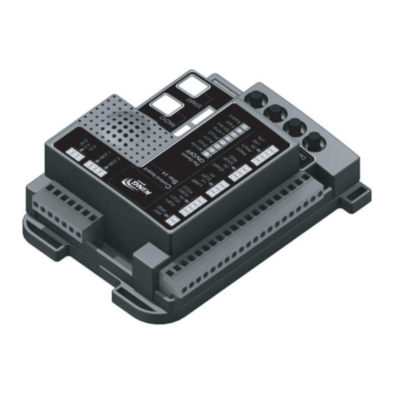
1- PRODUCT DESCRIPTION 1A - GENERAL DESCRIPTION Programming buttons Dip-switch function setting Signaling led (Paragraph 4A-5) (Paragraph 9) Setting trimmers (Paragraph 4b-8) Removable spare fuse... -
Page 3: Main Features
1B - STARTING MODALITY The control unit has been designed to manage one 230Vac motors gate automations. To start the system it is necessary to: 1- Connect the power supply and the accessories as indicated in the 2nd paragraph 2- Set the dip-switches (paragraph 4A) and the trimmers (paragraph 4B) depending on the wanted functioning and on the conditions of the system. -
Page 4: Electric Connections
2 - ELECTRIC CONNECTIONS 2A - CABLES SECTION - The control unit must be powered (by its external fuse box terminal), through a cable which must be at least 3x1.5 mm² wide. If the distance between the control unit and the grounding system is more than 30m it is necessary to install an electric discharger near to the control unit. - Page 5 PLEASE NOTE: - Every contact which will be connected to the control unit must be free contact. - The limit switches (terminals 4,5,6), if not used, have to be free (not bridged). The control unit activate the contact only if it receive signals from connected contacts.
-
Page 6: Control Unit Settings
4 - CONTROL UNIT SETTINGS 4A - DIP-SWITCHES SETTINGS A variation on the DIP position does not require a another programming procedure. DESCRIPTION DIP STATUS FUNCTIONING RADIO START radio channel programming procedure (see paragraph 3A) Pedestrian opening radio channel programming procedure (see paragraph 3B) Yes rapid automatic reclosing FAST No rapid automatic reclosing... - Page 7 5 - DIP-SWITCHES DESCRIPTION 5A - DIP-SWITCH 1 - RADIO If the “RADIO” dip-switch is set to ON, the START channel is memorized during the programming of the radio transmitter (see paragraph 3). If the “RADIO” dip-switch is set to OFF, the pedestrian opening channel is memorized during the programming of the radio transmitter (see paragraph 3).
- Page 8 6 - TRAVEL PROGRAMMING PROCEDURE It is necessary to perform the learning procedure to program the travel (see paragraph 6B for the standard proce- dure, or paragraph 6D for the professional procedure). There is also a learning procedure for the pedestrian opening (see paragraph 6E;...
- Page 9 6D - PROFESSIONAL LEARNING PROCEDURE The installer can set the beginning point of the slowdown through this procedure. The beginning point is customizable in opening and closing. 2. RESET: push the 1. Place the wing in 3. The yellow led SET button for middle position.
- Page 10 7 - PARTIAL OPENING LEARNING PROCEDURE The pedestrian opening is a partial opening (or total opening, if the installer wants it) of the wing. To manage the pedestrian opening, it is necessary to program a button of the radio transmitter (see paragraph 3B), or connect a command by wire on the terminals 10,12 (see paragraph 10B).
-
Page 11: Control Unit
2C - CONNECTION OF 2 SLIDING GATES WORKING IN THE SAME ENTRANCE The control by wire (stop, closing and start), and the safety devices functioning (”PHO1” and “PHO2”) are unified by the following connection. The photocell contact must be sent to both the control units on the same input (”PHO1” or “PHO2”). CONTROL UNIT 1 CONTROL UNIT 2 TO BE CONNECTED ON... - Page 12 10 - CABLE COMMANDS CONNECTABLE 10A - STARTING COMMAND CONNECTION In the “START” input (terminals 9, 10) it is possible to connect a normally open contact (for example, key selectors, or switches) to manage the automation. The commands can be set by dip switches 6 and 7 (see paragraph 4A, 5). There are 2 micro switches in the selectors;...
-
Page 13: Operation Of The Safety Devices
11 - OPERATION OF THE SAFETY DEVICES 11A - CLOSING SAFETY DEVICES It is possible to connect normally closed contact devices to the “PHO1” input (terminal 13,15). These devices operate during the closing cycle. In particular: - in closing phase, an immediate inversion of the motion. - in opening phase, they have no effect. - Page 14 12 - OTHER CONNECTABLE ACCESSORIES 12A - FLASHING LAMP It is possible to connect flashing light devices to the “LAMP” input (terminals 28, 29). These devices turn on a second before the manoeuvre. If the dip 4 “LAMP” is ON position, the power supplied is intermittent. Therefore, a normal lamp can be connected. If the dip 4 “LAMP”...
- Page 15 14 - INCONVENIENTS AND REMEDIES 14A - THE AUTOMATION DOESN’T START - Verify the presence of voltage in the terminals of the external fuse box. - Verify the fuse (see paragraph 1A). - STOP contact open (red led “ST” is off): check for possible STOP commands connected (terminal 11). If absent, jumper the input with terminal 10.
-
Page 16: Made In Italy
MADE IN ITALY King Gates S.r.l. Via A. Malignani, 42 - 33077 Sacile (PN) ITALY Tel. +39 0434 737082 - Fax +39 0434 785351 e-mail: info@king-gates.com web: www.king-gates.com...
Need help?
Do you have a question about the Star D1230 and is the answer not in the manual?
Questions and answers