
Subscribe to Our Youtube Channel
Related Manuals for King gates Star D124


Summary of Contents for King gates Star D124
- Page 1 Star D124 Star D124= Control unit for 1 24Vdc motors INSTRUCTION MANUAL ONLY FOR DEBUG...
-
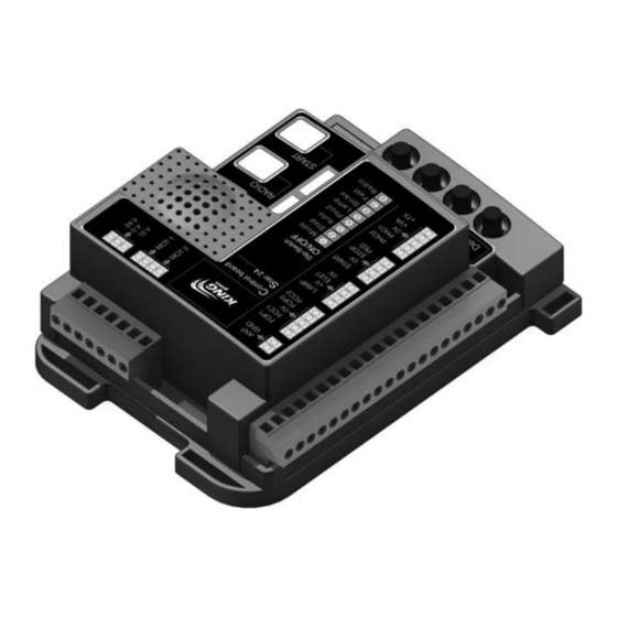
Page 2: Product Description
1- PRODUCT DESCRIPTION 1A - GENERAL DESCRIPTION Programming buttons Dip-switch function setting Signaling led (Paragraph 4A-5) (Paragraph 9) Setting trimmers (Paragraph 4b-8) Removable spare fuse 2A accessories fuse “RX Star” radio code receiver 433.920Mhz “MEMO” (Paragraph 13B) Extractable memory (Paragraph 13A) External Power connection... -
Page 3: Main Features
1B - STARTING MODALITY The control unit has been designed to manage one 24Vdc motors gate automations. To start the system it is necessary to: 1- Connect the power supply and the accessories as indicated in the 2nd paragraph 2- Set the dip-switches (paragraph 4A) and the trimmers (paragraph 4B) depending on the wanted functioning and on the conditions of the system. -
Page 4: Electric Connections
2 - ELECTRIC CONNECTIONS 2A - CABLES SECTION - The control unit must be powered (by its external fuse box terminal), through a cable which must be at least 3x1.5 mm² wide. If the distance between the control unit and the grounding system is more than 30m it is necessary to install an electric discharger near to the control unit. - Page 5 3 - RADIOTRANSMITTERS PROGRAMMING PROCEDURE 3A - START CHANNEL PROGRAMMING PROCEDURE Power the control Press button RADIO Make a transmission unit and set for 2 seconds. pressing the desired Dip 8 (RADIO) to ON. (the red LED comes on). key on the transmitter. During entry, Memorize all the At the end of the operation,...
-
Page 6: Control Unit Settings
4 - CONTROL UNIT SETTINGS 4A - DIP-SWITCHES SETTINGS A variation on the DIP position does not require a another programming procedure. DESCRIPTION DIP STATUS FUNCTIONING Slowdown enabled SLOW Slowdown disabled Opening / Stop / Closing / Stop modality (step by step) STEP Opening / Pause / Closing (it accepts only opening commands) Yes automatic reclosing (set by “PAU”... - Page 7 5 - DIP-SWITCHES DESCRIPTION 5A - DIP-SWITCH 1 - SLOW If the “SLOW” dip-switch is set to ON, the control unit enables the slowdowns. Using the standard programming procedure, they are equal to the 15% of the travel, but they can be customized by the professional programming procedure (see paragraph 6D). If the “SLOW”...
- Page 8 6 - TRAVEL PROGRAMMING PROCEDURE It is necessary to perform the learning procedure to program the travel (see paragraph 6B for the standard proce- dure, or paragraph 6D for the professional procedure). There is also a learning procedure for the pedestrian opening (see paragraph 6E;...
- Page 9 6D - PROFESSIONAL LEARNING PROCEDURE The installer can set the beginning point of the slowdown through this procedure. The beginning point is customizable in opening and closing. 2. RESET: push the 1. Place the wing in 3. The yellow led SET button for middle position.
- Page 10 7 - PARTIAL OPENING LEARNING PROCEDURE The pedestrian opening is a partial opening (or total opening, if the installer wants it) of the wing. To manage the pedestria n opening, it is necessary to program a button of the radio tran smitter (see paragraph 3B), or connect a command by wire on the terminals 14,15 (see paragraph 10B).
-
Page 11: Control Unit
8 - CONNECTION OF 2 SLIDING GATES WORKING IN THE SAME ENTRANCE The control by wire (stop, closing and start), and the safety devices functioning (”PHO1” and “PHO2”) are unified by the following connection. ! The photocell contact must be sent to both the control units on the same input (”PHO1” or “PHO2”). CONTROL UNIT 1 CONTROL UNIT 2 TO BE CONNECTED ON... - Page 12 10 - CABLE COMMANDS CONNECTABLE 10A - STARTING COMMAND CONNECTION In the “START” input (terminals 12, 13) it is possible to connect a normally open contact (for example, key selectors, or switches) to manage the automation. The commands can be set by dip switches 2, 3 and 7 (see paragraph 4A, 5). There are 2 micro switches in the selectors;...
-
Page 13: Operation Of The Safety Devices
11 - OPERATION OF THE SAFETY DEVICES 11A - CLOSING SAFETY DEVICES It is possible to connect normally closed contact devices to the “PHO1” input (terminal 16,18). These devices operate during the closing cycle. In particular: - in closing phase, an immediate inversion of the motion. - in opening phase, they have no effect. - Page 14 12 - OTHER CONNECTABLE ACCESSORIES 12A - FLASHING LAMP It is possible to connect flashing light devices to the “LAMP” input (terminals 8,9). These devices turn on a second before the manoeuvre. If the dip 5 “LAMP” is ON position, the power supplied is intermittent. Therefore, a normal lamp can be connected. If the dip 5 “LAMP”...
- Page 15 14 - INCONVENIENTS AND REMEDIES 14A - THE AUTOMATION DOESN’T START - Verify the presence of voltage in the terminals of the external fuse box. - Verify the fuse (see paragraph 1A). - STOP contact open (red led “ST” is off): check for possible STOP commands connected (terminal 14). If absent, jumper the input with terminal 14.
-
Page 16: Made In Italy
MADE IN ITALY King Gates S.r.l. Via A. Malignani, 42 - 33077 Sacile (PN) ITALY Tel. +39 0434 737082 - Fax +39 0434 785351 e-mail: info@king-gates.com web: www.king-gates.com...
Need help?
Do you have a question about the Star D124 and is the answer not in the manual?
Questions and answers
bonjour ,ou se trouve le dipo8 radio pour programer de nouvelle telecommande