Advertisement
Advertisement
Table of Contents

Related Manuals for King gates Star 2230


Summary of Contents for King gates Star 2230
- Page 1 Star 2230 Star 2230= Control unit for 1 or 2 230Vac motors INSTRUCTION MANUAL...
-
Page 2: Product Description
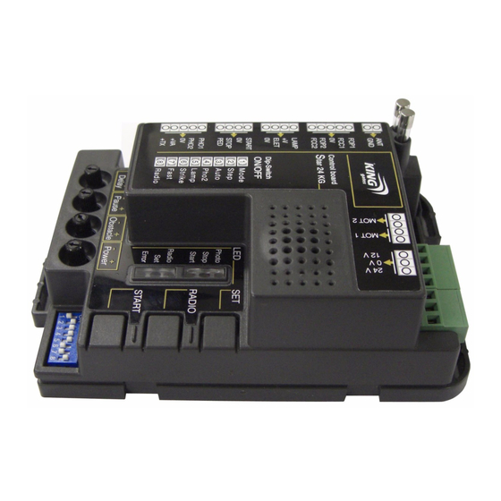
1- PRODUCT DESCRIPTION 1A - GENERAL DESCRIPTION Programming buttons Dip-switch function setting Signaling led (Paragraph 4A-5) (Paragraph 9) Setting trimmers (Paragraph 4b-8) Removable spare fuse... -
Page 3: Main Features
1B - STARTING MODALITY The control unit has been designed to manage 1 or 2 230 Vac motors gate automations. To start the system it is necessary to: 1- Connect the power supply, the motors, and the accessories as indicated in the 2nd paragraph 2- Set the dip-switches (paragraph 4A) and the trimmers (paragraph 4B) depending on the wanted functioning and on the conditions of the system. -
Page 4: Electric Connections
2 - ELECTRIC CONNECTIONS 2A - CABLES SECTION - The control unit must be powered (by its external fuse box terminal), through a cable which must be at least 3x1.5 mm² wide. If the distance between the control unit and the grounding system is more than 30m it is necessary to install an electric discharger near to the control unit. - Page 5 PLEASE NOTE: - Every contact which will be connected to the control unit must be free contact. - The limit switches (terminals 4,5,6,7,8), if not used, have to be free (not bridged). The control unit activate the contact only if it receive signals from connected contacts.
- Page 6 2 - ELECTRIC CONNECTIONS 2A - CABLES SECTION - The control unit must be powered (by its external fuse box terminal), through a cable which must be at least 3x1.5 mm² wide. If the distance between the control unit and the grounding system is more than 30m it is necessary to install an electric discharger near to the control unit.
- Page 7 PLEASE NOTE: - Every contact which will be connected to the control unit must be free contact. - The limit switches (terminals 4,5,6,7,8), if not used, have to be free (not bridged). The control unit activate the contact only if it receive signals from connected contacts.
-
Page 8: Control Unit Settings
4 - CONTROL UNIT SETTINGS 4A - DIP-SWITCHES SETTINGS A change of the DIP 8 “SLOW” needs the repetition of the programming procedure. It is advised to maintain slow-down active to improve gate and motor mechanics life. DESCRIPTION DIP STATUS FUNCTIONING RADIO START radio channel programming procedure (see paragraph 3A) Pedestrian opening radio channel programming procedure (see paragraph 3B) - Page 9 5 - DIP-SWITCHES DESCRIPTION 5A - DIP-SWITCH 1 - RADIO If the “RADIO” dip-switch is set to ON, the START channel is memorized during the programming of the radio transmitter (see paragraph 3). If the “RADIO” dip-switch is set to OFF, the pedestrian opening channel is memorized during the programming of the radio transmitter (see paragraph 3).
- Page 10 6 - TRAVEL PROGRAMMING PROCEDURE It is necessary to perform the learning procedure to program the travel (see paragraph 6B for the standard proce- dure, or paragraph 6D for the professional procedure). There is also a learning procedure for the pedestrian opening (see paragraph 6E;...
- Page 11 6D - PROFESSIONAL LEARNING PROCEDURE The installer can set the beginning point of the slowdown through this procedure. The beginning point is customizable in opening and closing. On steps 9a and 12a of the programming procedure, the first wing is the one which opens as first and closes as second (connected to terminals 30,31,32 “MOT1”).
- Page 12 7 - PARTIAL OPENING LEARNING PROCEDURE The pedestrian opening is a partial opening (or total opening, if the installer wants it) of the wing opened by “MOT1” (terminals 30,31,32). To manage the pedestrian opening, it is necessary to program a button of the radio transmitter (see paragraph 3B), or connect a command by wire on the terminals 10,12(see paragraph 10B).
- Page 13 8 - TRIMMER 8A - Trimmer “FOR” – Power / speed of the motor Use the “FOR” trimmer to adjust the voltage with which the motor is powered during operation, thus adjusting its speed. This is settable between 50% and 100% of the maximum force and can be increased by turning the trimmer clockwise. Thus if the trimmer is set on the minimum then the speed is equal to about 50%, if adjusted in an intermediate position it is equal to 75%, while at the maximum the speed will be the largest obtainable.
- Page 14 10 - CABLE COMMANDS CONNECTABLE 10A - STARTING COMMAND CONNECTION In the “START” input (terminals 9,10) it is possible to connect a normally open contact (for example, key selectors, or switches) to manage the automation. The commands can be set by dip switches 6 and 7 (see paragraph 4A, 5). There are 2 micro switches in the selectors;...
-
Page 15: Operation Of The Safety Devices
11 - OPERATION OF THE SAFETY DEVICES 11A - CLOSING SAFETY DEVICES It is possible to connect normally closed contact devices to the “PHO1” input (terminal 13,15). These devices operate during the closing cycle. In particular: - in closing phase, an immediate inversion of the motion. - in opening phase, they have no effect. -
Page 16: Made In Italy
MADE IN ITALY King Gates S.r.l. Via A. Malignani, 42 - 33077 Sacile (PN) ITALY Tel. +39 0434 737082 - Fax +39 0434 786031 e-mail: info@king-gates.com web: www.king-gates.com...
Need help?
Do you have a question about the Star 2230 and is the answer not in the manual?
Questions and answers