Table of Contents
Advertisement
Advertisement
Table of Contents

Related Manuals for Center 520


Summary of Contents for Center 520
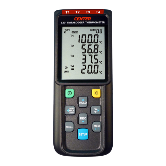
- Page 1 Data Logger / K,J,E,T, Type THERMOMETER SE-520...
-
Page 2: Table Of Contents
7.3.5 Set T1-T2 subtraction mode.………………...…........9 7.3.6 Set auto power off time.…………..……………….………......9 7.3.7 Set system clock.………………………….………........9 7.4 Clearing Data Logger Records.……..………………........10 7.5 Clearing Instant Read-out Memory.…..…………….………......10 7.6 Connecting To A computer.…………….….…………........10 8. Power Preparation………………………………………………………………...10 8.1 Battery Replacement……………………………………………………….....10 9. Testlink SE-520 Software………………………………………….…….....11 10. Maintenance.….….……………………………………………………………...…..…17... -
Page 3: General Description
DATALOGGER THERMOMETER 1. GENERAL DESCRIPTION Thank you for choosing our data logger thermometer. To ensure the safety and the best performance of this instrument, we recommend you to read and follow the manual carefully before operation. Data can be stored in the meter or directly saved on a computer through PC interface. Recorded data can be further processed by PC computer. -
Page 4: Specifications
DATALOGGER THERMOMETER 4. SPECIFICATIONS Measurement range: K: -200°C ~1372°C (- 328°F ~ 2501°F) J: -200°C~1000°C (- 328°F ~ 1832°F) E: -200°C~750°C (- 328°F ~ 1382°F) T: -200°C~400°C (-328 °F ~ 752°F) Resolution: 0.1°C < 600°C / 0.1°F < 1000°F, 1°C ≧ 600°C / 1°F ≧1000°F Accuracy:... -
Page 5: Symbol Definition And Button Location
DATALOGGER THERMOMETER 5. SYMBOL DEFINITION & BUTTON LOCATION : Battery condition indicator : Minimum indicator : Maximum indicator : Average indicator : Setup option indicator : Auto Power Off enabled indicator : Recording data logger indicator : Memory full indicator : Memory group indicator : Recall Memory group reading indicator : Thermocouple type... - Page 6 DATALOGGER THERMOMETER ○ ○ Thermocouple Input REC Button ○ ○ Display Screen RECALL Saved Reading Button ○ ○ Power ON/OFF Button SETUP Button ○ ○ Back Light Button MEM Button (Set 100 Memory) ○ ○ MAX MIN AVG Button USB Interface ○...
-
Page 7: Button Instructions
DATALOGGER THERMOMETER 6. BUTTON INSTRUCTIONS 6.1 Power ON/OFF Button: Press the button to turn on the meter. Press and hold button for 3 seconds to turn off. 6.2 Backlight Button: Press to turn on the LCD backlight. This makes it easier to read in dark environment. Press again to turn off backlight. -
Page 8: Recall Saved Reading Button
DATALOGGER THERMOMETER 6.7 MAX/MIN/AVG Button: Under this mode, the unit simultaneously monitors and stores the maximum, minimum and average value in the memory. The unit will keep updating/refreshing the data. To start: (1) Press button. “ ” symbol lights up on LCD, the reading shows the maximum data. (2) Press button again to show minimum data;... - Page 9 DATALOGGER THERMOMETER Fig.2 Set interval time for data logging. Fig.3 Set offset to compensate for probe errors. Fig.4 Set alarm point. Fig.5 Set T1-T2 subtraction mode. Fig.6 Set auto power off time.
-
Page 10: Menu Description
DATALOGGER THERMOMETER Fig.7 Set system clock. 7.3 Menu Description: 7.3.1 Select thermocouple type: K, J, E, or T Press the button to select thermocouple type. (see Fig.8) Fig.8 7.3.2 Setting interval time for data storing: (1) Press the button to set minute or second. (see Fig.9) (2) Press the button to increase / decrease value. -
Page 11: Set T1-T2 Subtraction Mode
DATALOGGER THERMOMETER Note: When measuring thermocouple value over alarm point, the symbol will blink “ ” or “ ” on the LCD. The beeper will make “ beep-beep-beep ” sound. The Lo alarm set cannot be greater than Hi alarm set. Fig.13 7.3.5 Set T1-T2 subtraction mode: Press the... -
Page 12: Clearing Data Logger Records
DATALOGGER THERMOMETER 7.4 Clearing Data Logger Records: (1) Turn off the unit. (2) Press and hold button and then press power button to turn on the unit. SUrE 5, (3) Keep holding button, then LCD will show " "," " and “ 4…1, 0 ”... -
Page 13: Testlink Se-520 Software
DATALOGGER THERMOMETER 9. Testlink SE-520 SOFTWARE 9.1 The SE-520 package contains: Software CD disk Micro USB cable 9.2 System Required: Windows XP/ VISTA/ Windows 7/ Windows 8/ Windows 10 9.3 Minimum Hardware Required: PC or laptop with CD-ROM drive. - Page 14 DATALOGGER THERMOMETER (2) There will be a save dialog window for you to choose the file name and file type to save. There are three types of file format you can choose, binary file(*.ghf), text file(*.txt) and EXCEL format file(*.csv). The *.ghf file use much fewer disk space to save the data than the other two file formats, but it can only be used in SE520.
- Page 15 DATALOGGER THERMOMETER 9.6 How to load the recorded data from the memory of 4 Channel Thermometer and save it to a file? (1) Power on the 4 Channel Thermometer. (2) Press the “ REC ” button of the meter to start recording data. (3) After a while, press “...
- Page 16 DATALOGGER THERMOMETER DataLogger: By opening the DataLogger Window, the user can load recorded data of meter to PC in this window. Output To Graph - Graphing tabular data. 9.8 DataLogger: When you have the theromameter connceted to PC, select " DataLogger " from main menu or click Datalogger icon from tool bar to load recorded data from the meter and there will be a progress indicator to show the loading status.
- Page 17 DATALOGGER THERMOMETER It will transfer first data set to graph on the right hand side. The user can also click at any other data set to choose that set for graph. Graph: Tool Bar: - Display or hide Statistic1. - Display or hide Statistic2. - Normal cursor.
- Page 18 DATALOGGER THERMOMETER - Seperate the four channel. - Combine the four channel. - Graph Customization - Change the Y axis extention Note: When the Split is unchecked, graph will use T1 as the Y axis display range.
-
Page 19: Maintenance
DATALOGGER THERMOMETER - To Undo the Zoom You can Zoom this graph by using mouse: To Zoom: (1) Press the left mouse button and drag the cursor to select the new extents. (2) Release the mouse button. You can choose channel number showing in the graph. a. - Page 20 CENTER TECHNOLOGY CORP. 4F, NO.415, Jung-Jeng Rd., Shu-Lin Dist., New Taipei City 238, Taiwan TEL: 886-2-26763926 E-Mail : center@centertek.com FAX: 886-2-26763925 http : / / www.centertek.com GCA000520-02000 Distributor in Australia Pacific Sensor Technologies Pty Ltd Unit 4, 3 Neutron Place Rowville, VIC 3178 Australia 1300 662 720 | sales@pacificsensortech.com.au...
Need help?
Do you have a question about the 520 and is the answer not in the manual?
Questions and answers