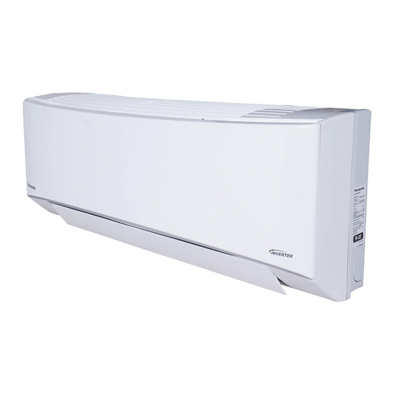
Panasonic CS/CU-EU12AKY Series Operating & Installation Instructions Manual

Panasonic CS/CU-EU12AKY Series Operating & Installation Instructions Manual

Advertisement

Operating & Installation
Instructions
Air conditioner
Model No.
CS/CU-EU12AKY series
CS/CU-EU18AKY series
CS/CU-EU24AKY series
CS/CU-VU18AKY series
CS/CU-KU12AKY series
CS/CU-KU18AKY series
CS/CU-KU24AKY series
CS/CU-YU12AKY series
CS/CU-YU18AKY series
CS/CU-YU24AKY series
CS/CU-NU12ZKY series
CS/CU-NU18ZKY series
CS/CU-NU24ZKY series
CS/CU-TU12AKY series
CS/CU-TU18AKY series
CS/CU-TU18ZKY series
CS/CU-SU12ZKY series
CS/CU-SU18ZKY series
CS/CU-SU24ZKY series
CS/CU-KZ18AKY series
CS/CU-KZ24AKY series
This symbol shows that this equipment uses a
flammable refrigerant. If the refrigerant is leaked,
together with an external ignition source, there is
WARNING
a possibility of ignition.
This symbol shows that a service personnel
should be handling this equipment with reference
to the Installation Instructions.
Installation & Operating Instructions
Air Conditioner
Thank you for purchasing Panasonic Air Conditioner.
Before installation & operating the unit, please read these
instructions thoroughly and keep them for future reference.
Before installation, the installer should:
Read the Installation & Operating Instructions, then request
the customer keep them for future reference.
Remove the remote control packed with the indoor unit.
This symbol shows that the Operation
Instructions should be read carefully.
This symbol shows that there is information
included in the Operation Instructions
and/or Installation Instructions.
* Images are for
Illustration purpose
only.
ACXF55-38530-AA
ACXF55-38530-AA

Advertisement

Table of Contents
loading

Summary of Contents for Panasonic CS/CU-EU12AKY Series

  • Page 1 CS/CU-KZ18AKY series CS/CU-KZ24AKY series Installation & Operating Instructions Air Conditioner Thank you for purchasing Panasonic Air Conditioner. Before installation & operating the unit, please read these instructions thoroughly and keep them for future reference. Before installation, the installer should: Read the Installation & Operating Instructions, then request the customer keep them for future reference.
  • Page 2: Table Of Contents

    Table of contents Safety precautions ......4-9 How to use ........10-11 To Learn more........12 • Replace the batteries when remote display Cleaning instructions ......13 blinks “ ”. Troubleshooting ........14 Installation instructions ....16-26 Safety precautions ......27 BEE Regulation ......
  • Page 3 MODE TEMP SMART POWERFUL POWERFUL POWERFUL SMART SMART MODE SWING MODE SWING SLEEP FAN SPEED SWING TEMP TEMP FAN SPEED FAN SPEED SWING SWING DISPLAY CLEAN converti7 TIMER SLEEP CLEAN SLEEP CLEAN converti7 converti7 CANCEL TIMER TIMER CANCEL CANCEL CHECK LOCK RESET CHECK...
  • Page 4: Safety Precautions

    Safety precautions To prevent personal injury, injury to others or property damage, please comply with the following: WARNING Incorrect operation due to failure to follow instructions below may cause harm or damage, the seriousness of which is classified as below: Indoor unit and outdoor unit This appliance is not intended for use by This appliance is filled with R32 (mild...
  • Page 5 Remote control Precaution for using R32 refrigerant The basic installation work procedures are the same as Do not allow infants and small children to play conventional refrigerant (R410A, R22) models. with the remote control to prevent them from accidentally swallowing the batteries. Since the working pressure is higher than that of refrigerant R22 models, some of the piping and Power supply...
  • Page 6 Safety precautions Prevent water leakage by ensuring drainage 2. Servicing 2-1. Service personnel pipe is: • Any qualifi ed person who is involved with - Connected properly, working on or breaking into a refrigerant - Kept clear of gutters and containers, or circuit should hold a current valid certifi cate - Not immersed in water from an industry-accredited assessment...
  • Page 7 2-4. Presence of fi re extinguisher 2-8. Checks to electrical devices • If any hot work is to be conducted on the • Repair and maintenance to electrical refrigeration equipment or any associated components shall include initial safety parts, appropriate fi re extinguishing checks and component inspection equipment shall be available at hand.
  • Page 8 Safety precautions 4. Repair to intrinsically safe components 8. Removal and evacuation • When breaking into the refrigerant circuit to make • Do not apply any permanent inductive or repairs – or for any other purpose – conventional capacitance loads to the circuit without procedures shall be used.
  • Page 9 10. Decommissioning 12. Recovery • Before carrying out this procedure, it is • When removing refrigerant from a system, essential that the technician is completely either for servicing or decommissioning, familiar with the equipment and all its details. it is recommended good practice that all •...
  • Page 10: How To Use

    How to use (For COOLING Models) Remote control receiver and AUTO - For your convenience indicator Unit run with optimised settings. You can change the temperature according to your comfort. COOL - To enjoy cool air To reduce power consumption during COOL mode, TIMER TIMER POWERFUL...
  • Page 11 AUTO (Quiet) (Low) (Medium) (High) TIMER CANCEL Example: Select ON or OFF To adjust airflow direction OFF at 14:00 AIR SWING timer • Press the OFF button. Set the time (Vertical) • Press OFF button again to increase timer time in step (Horizontal) of “10”...
  • Page 12: To Learn More

    To Learn more... To select different Performance modes This operation Changes Air Conditioner Performance in COOL Mode only. converti7 • Step 1 : “HC” is display on Unit and Remote. Unit will operate in High Capacity Mode. • Step 2 : “FC” is display on Unit and Remote. Unit Input Power will be upto 100%. •...
  • Page 13: Cleaning Instructions

    *Ag Clean Dust filters Filter PM0.1 Filters Dust filters • Wash/rinse the dust filters gently with water to avoid damage to the filter surface. • Dry the dust filters thoroughly under shade, away from fire or direct sunlight. • Replace any damaged filters. Please remove the Ag Clean Filter / PM0.1 Filter before wash/rinse the dust filter with water.
  • Page 14: Troubleshooting

    Wi-Fi LED stays ON during unit turn OFF. Unit’s Wi-Fi connection with the router is activated. Wi-Fi LED continuously blinking. Check unit’s Wi-Fi connection with router. The unit stops and some alpha-numeric codes appear on IDU display.
  • Page 15 Notes...
  • Page 16: Installation Instructions

    Installation instructions Select the Best Location Indoor Unit Outdoor Unit • Do not install the unit in excessive oil fume area such • If an awning is built over the unit to prevent direct as kitchen, workshop and etc. sunlight or rain, be careful that heat radiation from •...
  • Page 17 Indoor / Outdoor Unit Installation Diagram WARNING Installation parts you should purchase ( ) Flare connection only at outside of building Attaching the remote control holder to the wall Installation Remote control holder fi xing screws plate Bushing-Sleeve ( ) Remote control Sleeve ( )
  • Page 18 Installation instructions Indoor Unit How to Fix Installation Plate The mounting wall shall be strong and solid enough to prevent it from vibration. Wall Wall Wall More than More than Indoor unit More than screw 128 mm 241.5 mm 241.5 mm Installation plate Measuring Tape...
  • Page 19 Indoor Unit Installation • Do not turn over the unit without it’s shock absorber during pull out the piping. It may cause intake grille damage. • Use shock absorber during pull out the piping to protect the intake grille from damage. Piping Piping Shock absorber...
  • Page 20 Installation instructions Step-4 Cut and fl are the embedded piping Insert the connection cable When determining the dimensions of the piping, • slide the unit all the way to the left on the installation Connection cable plate. Gas side piping Refer to the section “Cutting and fl...
  • Page 21 Connect the Cable to the Indoor Unit The power supply cord, indoor and outdoor unit connection cable can be connected without removing the front grille. Install the indoor unit on the installing holder that mounted on the wall. Open the front panel and grille door by loosening the screw. Cable connection to the power supply through Isolating Devices (Disconnecting means).
  • Page 22 Installation instructions Wire Stripping And Connecting Requirement Wire stripping Indoor/outdoor connection terminal board Conductor Conductor over Conductor not fully inserted inserted fully inserted No loose strand when inserted ACCEPT PROHIBITED PROHIBITED 5 mm or more (gap between wires) RISK OF FIRE JOINING OF WIRES MAY CAUSE OVERHEATING AND FIRE.
  • Page 23 Installation instruction Outdoor Unit Install the Outdoor Unit • After selecting the best location, start installation to Indoor/Outdoor Unit Installation Diagram. 1. Fix the unit on concrete or rigid frame firmly and horizontally by bolt nut (ø10 mm). 2. When installing at roof, please consider strong wind and earthquake. Please fasten the installation stand firmly with bolt, screws or nails.
  • Page 24 4. Close the Low side valve of the charging set and turn off the vacuum pump. Make sure that the needle in the Liquid side Indoor unit Outdoor unit Two-way valve gauge does not move after approximately five minutes. Note : BE SURE TO TAKE THIS PROCEDURE IN ORDER TO AVOID REFRIGERANT GAS Close LEAKAGE.
  • Page 25 Cutting and Flaring the Piping Please cut using pipe cutter and then remove the burrs. Remove the burrs by using reamer. If burrs is not removed, gas leakage may be caused. Turn the piping end down to avoid the metal powder entering the pipe. Improper fl...
  • Page 26 In Case of Reusing Existing Refrigerant Piping Observe the followings to decide reusing the existing refrigerant piping. Poor refrigerant piping could result in product failure. • In the circumstances listed below, do not reuse any refrigerant piping. Instead, make sure to install a new piping. Heat insulation is not provided for either liquid-side or gas-side piping or both.
  • Page 27: Safety Precautions

    Safety precautions SAFETY PRECAUTIONS • Read the following “SAFETY PRECAUTIONS” carefully before installation. • Electrical work must be installed by a licensed electrician. Be sure to use the correct rating of the power plug and main circuit for the model to be installed. •...
  • Page 28: Bee Regulation

    BEE Regulation (For COOLING Models) Testing Guidelines Cooling Test Mode for Full Load (100%) and Half Load (50%) • Turn on the unit. 1) Mode : Select ‘COOL’ 2) Temperature : a) 16 ºC for Full Load (100%) : b) 17 ºC for Half Load (50%) 3) Air Swing et vane position to 3rd step from top (For Full Load)
  • Page 29 BEE Regulation (For HOT & COLD Models) Testing Guidelines Cooling Capacity Test Method (For COOL Mode) • Turn on the main power supply to unit. 1) Mode : Select ‘COOL’ 2) Temperature : a) Set Temp. 16 ºC for Full QUIET CLEAN Load (100%)
  • Page 30: Warranty Card

    Sr.No.A - Dear Customer, Thank you for buying this Panasonic product. This card entitles you to enjoy 1 year warranty on the product. Additionally, the Rotary Compressor fitted in all Panasonic Domestic One to One Split Air-Conditioners up to 5 Ton &...
  • Page 31 Purchase Invoice (“Warranty Period”); For Rotary Compressor in all Panasonic Domestic one to one Split Air-Conditioners up to 5 Ton and Scroll Compressor fitted in One to One High wall split Inverter model up to 2.5 Ton the warranty shall be valid 10 years (1 year Comprehensive + 9 years Additional) from the date of purchase mentioned on Purchase Invoice (“Warranty Period”);...
  • Page 32: Information

    Panasonic service center when disposing of this product. Customer care number ( Toll free ) : 1800 103 1333 ,1800 108 1333 Please see the Panasonic website for further information on collection centers, etc. or call the customer care toll-free number http://www.panasonic.com/in/corporate/sustainability/panasonic-india-i-recycle-program.html Do’s &...

Table of Contents