Advertisement
Quick Links
Installation and Operation Manual
The following guidelines should be followed to achieve
optimum pump performance.
Mounting Location
1. Locate in a dry position with adequate ventilation
and no more than 3 metres from the tank. Ensure the
pump cannot be submerged in water in normal use
and not likely to be sprayed.
2. Pump can be mounted horizontally or vertically (we
recommend the pump head is below motor level).
3. Feet positions are adjustable to allow replacement
of other pump types. Use No. 8 stainless steel screws
to fasten pump to solid surface, which supports the
pump securely.
Electrical
1. Use specified fuse, as indicated on motor label, in
the circuit.
2. Connect red wire to positive, black wire to
negative - recommended wire size is 2.5mm² (AWG
13).
3. Fit an isolating switch with adequate current
rating on the positive side of the supply.
4. To prevent the pump running continuously, turn off
at isolating switch when vehicle is left unattended or
water supply has been allowed to empty.
Plumbing
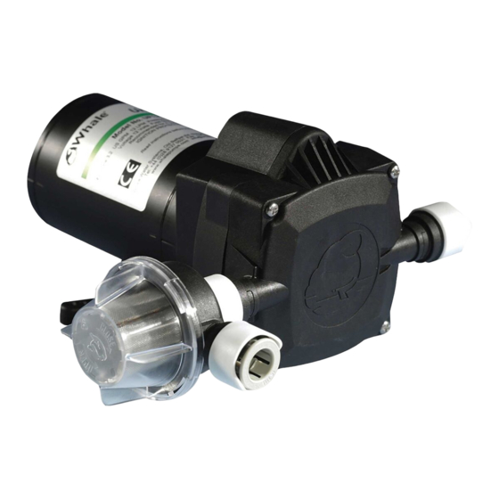
1. Ensure that the strainer provided is attached to the
pump head inlet (as shown below).
2. Check pump flow direction (as indicated on pump
body).
3. Never use pipe sealant or sealing tapes on
To Retro fit other Pumps:
Use 1 / 2 " BSP Adaptor
(Retail Version Only: 2 fittings included)
Fittings included in
retail models only
White Signal Wire (Battery Voltage 12/24V +ve)
Battery
Universal Filter / Strainer
(Included)
Black(-ve)
Fuse
Universal Freshwater Pressure Pump
threaded adaptors, as these may enter the pump and
cause failure.
Winterizing
If water is allowed to freeze in the system, serious
damage to the pipework and pump may occur. To best
avoid this damage, completely drain the water system.
1. Drain the tank either using the pump or a drain
valve.
2. Open all the faucets (including drain valve) and
allow pump to purge the water from the system, then
turn the pump off.
3. Disconnect the pump and turn on to purge into an
adequate basin. Only reconnect the pump when the
water system it is to be used.
4. Remember to leave all faucets including showers
open to avoid any damage.
Service Kits
AK1316- Replacement Head Service Kit
AK1317- Microswitch Service Kit
AK1319- Replacement Strainer
Declaration of Conformity
We herewith declare that the Universal Pump range
conforms to the requirements of the EMC directive
89/336/EEC, and to the CE Marking Directive 93/68/EEC
AK1318 - Replacement Head Service Kit
Red(+ve)
For Flexible Hose Systems:
1 /
Use
" Barbed Adaptor
2
(Retail Version Only: 2 fittings included)
(UF1215BL: ⅝" barbed adaptor included)
Flow Direction
#8 Screw (Not Included)
Advertisement

Related Manuals for Whale UF1215


Summary of Contents for Whale UF1215
- Page 1 Universal Freshwater Pressure Pump threaded adaptors, as these may enter the pump and Installation and Operation Manual cause failure. The following guidelines should be followed to achieve optimum pump performance. Winterizing If water is allowed to freeze in the system, serious Mounting Location damage to the pipework and pump may occur.
- Page 2 Trouble Shooting Fault Cause Solution Check power supply No power to pump Attach leads/clean connections Check faucet microswitch if present Pump does not run Fuse has blown Replace fuse Blockage in pipework Check pipework for kinks Check that water tank is not empty Check strainer is not blocked No water getting to pump Check all connections from tank to inlet of pump...
Need help?
Do you have a question about the UF1215 and is the answer not in the manual?
Questions and answers
Is it possible to adjust my pump UF1215 it momentarily pumps about every minute when all taps are off there appears to be no leaks