Table of Contents
Advertisement
Quick Links
Instruction Manual
D100391X012
Fisher™ EDR and ETR easy-e™ Valves
Contents
. . . . . . . . . . . . . . . . . . . . . . . . . . . . . . . . .
. . . . . . . . . . . . . . . . . . . . . . . . . . . . .
. . . . . . . . . . . . . . . . . . . . . . . . . . . . . . . . .
. . . . . . . . . . . . . . . . . . . . . . . . . . . . . . .
. . . . . . . . . . . . . . . . . . . . . . . . .
. . . . . . . . . . . . . . . . . . . . . . . . . . . . . . . . . .
. . . . . . . . . . . . . . . . . . . . . . . . . . . . . . . . .
. . . . . . . . . . . . . . . . . . . . . . . . . . .
. . . . . . . . . . . . . . . . . . . . . . . . .
. . . . . . . . . . . . . . . . . . . . . . . . . . . . . . .
. . . . . . . . . . . . . . . . . . . . . . . . . . . . . . . . .
. . . . . . . . . . . . . . . . . . . . . . . . . . . . . . . . . . .
. . . . . . . . . . . . . . . . . . . . . . . . . . . . . . . . . . .
Introduction
Scope of Manual
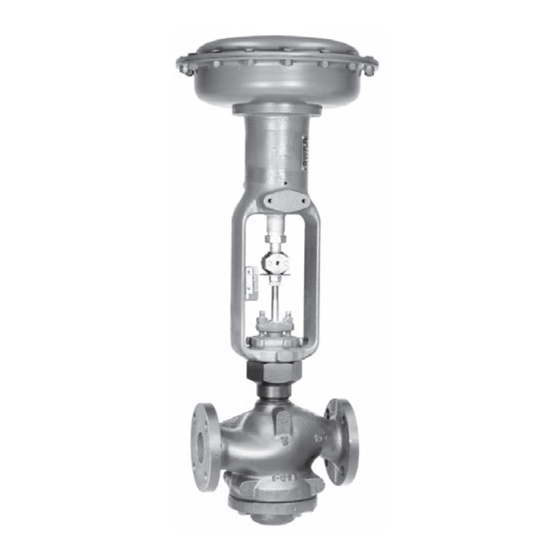
This instruction manual includes installation, maintenance, and parts information for NPS 1 through 4 EDR and ETR
valves (see figure 1). The valves are available in CL150 through 600 ratings.
The valves are also available with full-size and restricted-trim designs. Refer to separate manuals for instructions
covering the actuator and accessories.
Do not install, operate, or maintain an EDR or ETR valve without being fully trained and qualified in valve, actuator, and
accessory installation, operation, and maintenance. To avoid personal injury or property damage, it is important to
carefully read, understand, and follow all the contents of this manual, including all safety cautions and warnings. If you
have any questions about these instructions, contact your
proceeding.
Description
The EDR and ETR are single-port, globe-style valves that feature cage guiding, a balanced plug design, and
push-down-to-open valve plug action. The valve constructions are available with metal-to-metal or
metal-to-composition seats. These constructions permit access to the internal trim parts through the bottom flange
without removing the actuator from the valve.
www.Fisher.com
Figure 1. Reverse Acting easy-e Valve with Actuator
1
1
1
2
2
4
5
5
9
15
16
19
20
W2080-1
Emerson Process Management sales office
EDR and ETR Valves
March 2016
before
Advertisement
Table of Contents

Related Manuals for Emerson fisher ETR


Summary of Contents for Emerson fisher ETR
-
Page 1: Table Of Contents
To avoid personal injury or property damage, it is important to carefully read, understand, and follow all the contents of this manual, including all safety cautions and warnings. If you have any questions about these instructions, contact your Emerson Process Management sales office before proceeding. -
Page 2: Specifications
1. The pressure/temperature limits in this manual and any applicable standard or code limitation for the valve should not be exceeded. 2. Certain bonnet bolting material selections may require a CL600 easy‐e valve assembly to be derated. Contact your Emerson Process Management sales office. - Page 3 Instruction Manual EDR and ETR Valves D100391X012 March 2016 Figure 2. Actuator Mounting CAP SCREWS STEM CONNECTOR INDICATOR SCALE INDICATOR DISK ACTUATOR YOKE STEM LOCKNUTS PACKING FLANGE NUTS YOKE LOCKNUT BONNET W2080‐1 Table 2. Available Valve Constructions VALVE MATERIAL AND END CONNECTION STYLE VALVE Carbon Steel, Alloy Steel, or Stainless Steel Valve Cast Iron Valve...
-
Page 4: Installation
Shrunk‐fit pieces and threaded connections may loosen. In general, if post weld heat treating is to be performed, all trim parts should be removed. Contact your Emerson Process Management sales office for additional information. -
Page 5: Maintenance
Instruction Manual EDR and ETR Valves D100391X012 March 2016 Maintenance WARNING Avoid personal injury from sudden release of process pressure. Before performing any maintenance operations: D Do not remove the actuator from the valve while the valve is still pressurized. D Always wear protective gloves, clothing, and eyewear when performing any maintenance operations to avoid personal injury. - Page 6 Instruction Manual EDR and ETR Valves March 2016 D100391X012 Figure 3. Valve Plug Assembly STEM DISK SEAT DISK VALVE PLUG CAGE CASTLE NUT 40A5479‐B B2360 COTTER PIN ETR OR EDR NOTE: ETR USES A SEAL RING (KEY 24) AND A BACKUP RING (KEY 25) (SEE FIGURE 11). CAUTION Take care when removing the bottom flange (key 31) in the following procedure, to prevent possible product damage from parts unexpectedly falling out of the valve body.
- Page 7 4, 4 x 2‐1/2, or 4 x 3 1. Determined from laboratory tests. 2. SA193‐B8M annealed. 3. For other materials, contact your Emerson Process Management sales office. Replacing the Seal or Piston Ring CAUTION Be careful not to scratch the surface of the ring groove in the valve plug (key 2), or the new ring may not seal properly.
- Page 8 Instruction Manual EDR and ETR Valves March 2016 D100391X012 D For EDR, if the piston ring (key 6) is visibly damaged, remove the ring and replace it with a new part. Refer to the Parts List at the end of this manual for a replacement part. D For ETR, if the seal ring and backup ring (keys 24 and 25) are visibly damaged, remove the rings by prying or cutting them from the groove.
-
Page 9: Packing Maintenance
Instruction Manual EDR and ETR Valves D100391X012 March 2016 Installing the Parts into the Valve Body 1. Stack the valve trim parts using figures 11 and 12 to determine the sequence of parts. 2. Lubricate the stud bolts (key 15) before installing the valve trim into the valve body. (Note: For ease of installing trim parts, remove all packing parts from the packing box before installing the trim parts.) 3. - Page 10 Instruction Manual EDR and ETR Valves March 2016 D100391X012 actuator and release all pressure from the actuator. Use lock‐out procedures to be sure that the above measures stay in effect while you work on the equipment. 2. Exhaust all actuator pressure, disconnect the operating lines from the actuator, and disconnect any leakoff piping from the actuator.
- Page 11 Instruction Manual EDR and ETR Valves D100391X012 March 2016 6. Avoid scratching the packing box walls when removing the old packing parts. Clean the packing box (see figure 4), and clean, inspect, or replace metal packing parts. Generally, the metal packing parts are not part of the packing kits listed in the Parts List section, and they must be ordered individually.
- Page 12 Instruction Manual EDR and ETR Valves March 2016 D100391X012 Figure 5. Packing Arrangements UPPER WIPER UPPER WIPER (KEY 12) (KEY 12) PACKING PACKING FOLLOWER FOLLOWER FEMALE (KEY 13) (KEY 13) FEMALE ADAPTOR ADAPTOR PACKING RING PACKING RING MALE MALE ADAPTOR WASHER ADAPTOR SPACER (KEY 8)
- Page 13 Instruction Manual EDR and ETR Valves D100391X012 March 2016 Figure 6. Packing Arrangements UPPER WIPER (KEY 12) PACKING FOLLOWER (KEY 13) PACKING RING (KEY 7) LANTERN RING (KEY 8) PACKING BOX RING (KEY 11) 9.5 mm 12.7 mm 19.1 mm 12A8188‐A (3/8 INCH) (1/2 INCH)
- Page 14 Instruction Manual EDR and ETR Valves March 2016 D100391X012 Installing Packing If the trim is removed, refer to Trim Maintenance procedures, and install the trim (including the valve stem) before installing the packing. If necessary, use the Lapping Metal Seats procedures before installing packing. Key number locations are shown in figure 5 or 6 unless otherwise indicated.
-
Page 15: Parts Ordering
WARNING Use only genuine Fisher replacement parts. Components that are not supplied by Emerson Process Management should not, under any circumstances, be used in any Fisher valve, because they may void your warranty, might adversely affect the... -
Page 16: Packing Kits
Instruction Manual EDR and ETR Valves March 2016 D100391X012 Packing Kits Standard Packing Repair Kits (Non Live‐Loaded) Standard Packing Repair Kits (non live‐loaded) Stem Diameter, mm (Inches) 9.5 (3/8) 12.7 (1/2) 19.1 (3/4) Yoke Boss Diameter, mm (Inches) 54 (2‐1/8) 71 (2‐13/16) 90 (3‐9/16) PTFE (Contains keys 6, 8, 10, 11, and 12) - Page 17 Instruction Manual EDR and ETR Valves D100391X012 March 2016 ENVIRO‐SEAL Packing Repair Kits Repair kits include parts to replace the “soft” packing materials in valves that already have ENVIRO‐SEAL packing arrangements installed or in valves that have been upgraded with ENVIRO‐SEAL retrofit kits. Refer to figure 8 for key numbers for PTFE packing, to figure 9 for key numbers for graphite packing, and to figure 10 for key numbers for duplex packing.
- Page 18 Instruction Manual EDR and ETR Valves March 2016 D100391X012 Figure 8. Typical ENVIRO‐SEAL Packing System Figure 9. Typical ENVIRO‐SEAL Packing System with PTFE Packing with Graphite ULF Packing STUD (KEY 200) SPRING HEX NUT PACK (KEY 212) ASSEMBLY (KEY 217) PACKING GUIDE FLANGE...
-
Page 19: Parts Kits
Instruction Manual EDR and ETR Valves D100391X012 March 2016 Parts Kits Note Kits do not apply to alloy C (N10276 & CW2M), Alloy 20 (N08020 & CN7M), or alloy 400 (N04400 & M35‐1) trims. Kits for full‐ and restricted‐ capacity trims with service temperature to 593_C (1100_F) include S31600 [316 stainless steel (SST)] shim and N06600/graphite spiral wound gasket. -
Page 20: Parts List
27 Pipe nipple for optional lubricator/isolating valve 30* Lower Wiper, PTFE 31* Male Adapter, PTFE 32* Female Adaptor, PTFE Note Contact your Emerson Process Management sales office for Part Ordering information. Valve Assembly (figures 11 and 12) 1 Valve Body Bonnet Assembly (figure 4) If you need a valve body as a replacement part, order by valve... -
Page 21: D100391X012 March
Instruction Manual EDR and ETR Valves D100391X012 March 2016 Group 1 Actuators by Type Number 54 mm (2‐1/8 inches), 71 mm (2‐13/16 inches), or 90 mm (3‐9/16 inches) Yoke Boss 585C Series—50.8 mm (2 inches) maximum travel 585C 644 & 645 657 &... - Page 22 Instruction Manual EDR and ETR Valves March 2016 D100391X012 Figure 11. EDR and ETR with Full‐Size Trim Valve Assembly FLOW DIRECTION WHISPER TRIM STANDARD TRIM 40A5480‐D...
- Page 23 Instruction Manual EDR and ETR Valves D100391X012 March 2016 Figure 12. EDR and ETR with Restricted Trim Valve Assembly FLOW DIRECTION WHISPER TRIM 40A5482‐D STANDARD TRIM...
- Page 24 Responsibility for proper selection, use, and maintenance of any product remains solely with the purchaser and end user. Fisher, easy-e, ENVIRO-SEAL, and Whisper Trim are marks owned by one of the companies in the Emerson Process Management business unit of Emerson Electric Co.
Need help?
Do you have a question about the fisher ETR and is the answer not in the manual?
Questions and answers