Table of Contents
Advertisement
Quick Links
FOR YOUR SAFETY
If you smell gas:
1. Open windows.
2. DO NOT try to light any appliance.
3. DO NOT use electrical switches.
4. DO NOT use any telephone in
your building.
5. Extinguish any open flame.
6. Leave the building.
7. Immediately call your local gas
supplier after leaving the building.
Follow the gas supplier's
instructions.
8. If you cannot reach your gas
supplier, call the Fire Department.
WARNING
Fire Hazard
Keep all flammable objects, liquids and
vapors the minimum required clear-
ances to combustibles away from
heater.
Some objects will catch fire or explode
when placed close to heater.
Failure to follow these instructions can
result in death, injury or property
damage.
WARNING
Improper installation, adjustment, alteration, service
or maintenance can result in death, injury or
property damage. Read the Installation, Operation
and Service Manual thoroughly before installing or
servicing this equipment.
Installation must be done by a contractor qualified
in the installation and service of gas-fired heating
equipment or your gas supplier.
© 2012 Roberts-Gordon LLC
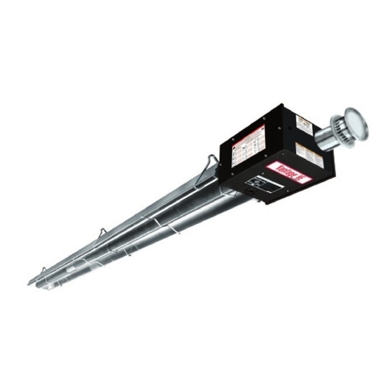
Vantage
Gas-Fired, Low Intensity
Unitary Heater Designed for
Harsh Environments
Installation, Operation &
Please take the time to read and understand
these instructions prior to any installation.
Installer must give a copy of this manual to the owner.
Keep this manual in a safe place in order to provide
your serviceman with necessary information.
Roberts-Gordon LLC
1250 William Street
P.O. Box 44
Buffalo, New York 14240-0044
Telephone: +1.716.852.4400
Fax: +1.716.852.0854
Toll Free: 800.828.7450
www.rg-inc.com
www.radiantheaters.com
®
HE
Service Manual
HE-40
HE-60
HE-80
HE-100
HE-125
HE-150
HE-175
Installer
Owner
P/N 132100NA Rev. H 03/12
Advertisement
Table of Contents
Troubleshooting

Subscribe to Our Youtube Channel
Related Manuals for Roberts Gorden Vantage HE-40


Summary of Contents for Roberts Gorden Vantage HE-40
- Page 1 FOR YOUR SAFETY If you smell gas: 1. Open windows. ® Vantage 2. DO NOT try to light any appliance. 3. DO NOT use electrical switches. 4. DO NOT use any telephone in your building. 5. Extinguish any open flame. 6.
-
Page 3: Table Of Contents
TABLE OF CONTENTS SECTION 1: Heater Safety............1 8.12 Outside Combustion Air Supply....... 40 1.1 Manpower Requirements ..........1 SECTION 9: Gas Piping............43 1.2 Safety Labels and Their Placement ......1 SECTION 10: Wiring.............. 45 1.3 California Proposition 65 ..........1 10.1 Line Voltage Thermostat Wiring....... - Page 5 TABLE OF FIGURES Figure 1: Top and Bottom Panel Label Placement ....2 Figure 2: Side and Back Panel Label Placement ...... 3 Figure 3: Standard Reflector ............ 7 Figure 4: One Side Reflector............ 7 Figure 5: Two Side Reflectors ..........7 Figure 6: 45°...
-
Page 7: Section 1: Heater Safety
SECTION 1: H EATER AFETY SECTION 1: HEATER SAFETY Your Safety is Important to Us! 1.1 Manpower Requirements This symbol is used throughout To prevent personal injury and damage to the heater, the manual to notify you of possi- two persons will be required for installation. ble fire, electrical or burn hazards. -
Page 8: Figure 1: Top And Bottom Panel Label Placement
HE-S ERIES NSTALLATION PERATION AND ERVICE ANUAL FIGURE 1: Top and Bottom Panel Label Placement Logo Label Rating Plate Label Bottom Panel Proposition 65 Label Top Panel Description Part Number Logo Label 91013201 Rating Plate Label 91010401 Gas Connection Label 91018122 Proposition 65 Label 91070015... -
Page 9: Figure 2: Side And Back Panel Label Placement
SECTION 1: H EATER AFETY FIGURE 2: Side and Back Panel Label Placement Control Side Panel Clearances to Combustibles Label Control Side Panel (Inside) Wiring Label Vent Length Label Back Panel Lighting Instruction Plate Label Description Part Number Clearances to Combustibles Label 91013415 Wiring Label 91013300... -
Page 10: Section 2: Installer Responsibility
HE-S ERIES NSTALLATION PERATION AND ERVICE ANUAL SECTION 2: INSTALLER RESPONSIBILITY The installer is responsible for the following: system which minimizes the lateral movement or swing which might damage reflectors. See Page • To install the heater, as well as the gas and elec- 17 , Figure 15. -
Page 11: Corrosive Chemicals
SECTION 2: I NSTALLER ESPONSIBILITY 2.2 Corrosive Chemicals CAUTION Product Damage Hazard Do not use heater in area containing corrosive chemicals. Refer to appropriate Material Safety Data Sheets (MSDS). Failure to follow these instructions can result in product damage. Roberts-Gordon LLC cannot be responsible for ensuring that all appropriate safety measures are undertaken prior to installation;... -
Page 12: Section 3: Clearances To Combustibles
HE-S ERIES NSTALLATION PERATION AND ERVICE ANUAL SECTION 3: CLEARANCES TO COMBUSTIBLES • Maintain clearances from swinging and overhead doors, overhead cranes, vehicle lifts, partitions, 3.1 Required Clearances to Combustibles storage racks, hoists, building construction, etc. WARNING • In locations used for the storage of combustible materials, signs must be posted to specify the maximum permissible stacking height to maintain required clearances from the heater to the com-... -
Page 13: Figure 3: Standard Reflector
SECTION 3: C LEARANCES TO OMBUSTIBLES NOTE: 1. All dimensions are from the surfaces of all tubes, couplings and elbows. 2. Clearances B, C and D can be reduced by 50% after 25' (7.5 m) of tubing downstream from where the burner and burner tube connect. FIGURE 3: STANDARD REFLECTOR (inches) (centimeters) -
Page 14: Figure 6: 45° Tilt Reflector
HE-S ERIES NSTALLATION PERATION AND ERVICE ANUAL NOTE: 1. All dimensions are from the surfaces of all tubes, couplings and elbows. 2. Clearances B, C and D can be reduced by 50% after 25' (7.5 m) of tubing downstream from where the burner and burner tube connect. °... -
Page 15: Figure 9: U-Tube, Opposite 45° Reflector
SECTION 3: C LEARANCES TO OMBUSTIBLES NOTE: 1. All dimensions are from the surfaces of all tubes, couplings and elbows. 2. Clearances B, C and D can be reduced by 50% after 25' (7.5 m) of tubing downstream from where the burner and burner tube connect. °... -
Page 16: Figure 12: Venting
HE-S ERIES NSTALLATION PERATION AND ERVICE ANUAL NOTE: 1. All dimensions are from the surfaces of all tubes, couplings and elbows. 2. Clearances B, C and D can be reduced by 50% after 25' (7.5 m) of tubing downstream from where the burner and burner tube connect. FIGURE 12: VENTING (inches) (centimeters) -
Page 17: Section 4: National Standards And Applicable Codes
SECTION 4: N ATIONAL TANDARDS AND PPLICABLE ODES SECTION 4: NATIONAL STANDARDS AND APPLICABLE CODES 4.1 Gas Codes 4.3 Public Garages The type of gas appearing on the nameplate Installation in garages must be in accordance must be the type of gas used. Installation must with the following codes: comply with national and local codes and United States: Refer to Standard for Parking... -
Page 18: Section 5: Major Components
HE-S ERIES NSTALLATION PERATION AND ERVICE ANUAL SECTION 5: MAJOR COMPONENTS FIGURE 13: Major Component Descriptions Burner with Tube Gasket Reflector Must be installed with the (Stainless Steel flame observation or Aluminum) window facing down. Alternate overlap as shown on overview and on Page 19, Figure 17. -
Page 19: Standard Parts List
SECTION 5: M AJOR OMPONENTS 5.1 Standard Parts List Table 1: Contents of Heater Burner Carton Part No. Description HE-40 HE-60 HE-80 HE-100 HE-125 HE-150 HE-175 032XXXXX Burner Assembly (Rate and Fuel Varies) 02568200 Gasket (Burner to Burner Tube) 132100NA Installation, Operation and Service Manual 94273914 Hex Head Bolts 5/16-18 Rolok... -
Page 20: Table 3: Component Package Guide
HE-S ERIES NSTALLATION PERATION AND ERVICE ANUAL Table 3: Component Package Guide Core and Extension Packages Model Tubing Length Aluminized Stainless Steel HE-40 10' (3 m) CP10ALUM CP10ALUMSS HE-60 20' (6 m) CP20ALUM CP20ALUMSS HE-80 20' (6 m) CP20ALUM CP20ALUMSS HE-100 30' (9 m) CP30ALUM... -
Page 21: Section 6: Heater Installation
SECTION 6: H EATER NSTALLATION SECTION 6: HEATER INSTALLATION Expansion and contraction of the tube dictates that the minimum suspension lengths in the table on WARNING Page 16, Figure 14 be maintained. Severe Injury Hazard Secure burner to burner tube with bolts and lockwashers. -
Page 22: Figure 14: Critical Hanger Placement (Indoor Installation)
HE-S ERIES NSTALLATION PERATION AND ERVICE ANUAL FIGURE 14: Critical Hanger Placement (Indoor Installation) Typical Suspension Details Beam Clamp Concrete Beam Wood Beam Anchor Locknut Screw Hook 3/8" Chain Size 3/16" Washers Rod 3/8" Minimum 24" min.* (61 cm) “X”* S-hooks Turnbuckle * Allows for thermal expansion of system... -
Page 23: Outdoor Mounting
SECTION 6: H EATER NSTALLATION 6.1 Outdoor Mounting may be parked within the clearances to combustibles. The heater is meant for stationary mounting in all sit- uations and should not be suspended from any struc- The bottom of the combustion air inlet shall not be ture which may become mobile or from any organic less than 12"... -
Page 24: Figure 16: Linear Heater Assembly Overview
HE-S ERIES NSTALLATION PERATION AND ERVICE ANUAL FIGURE 16: Linear Heater Assembly Overview... -
Page 25: Figure 17: Linear Heater Layout Overview
SECTION 6: H EATER NSTALLATION FIGURE 17: Linear Heater Layout Overview LEGEND Burner Reflector Tube HE-40 10' (3 m) Tube Length Tube/Reflector Hanger Coupling Assembly Vent Adapter a = 14" (36 cm) reflector width (not shown) HE-60 b = 2" (5 cm) 20' (6 m) Tube Length HE-80 end cap to burner... -
Page 26: Burner Tube Installation
HE-S ERIES NSTALLATION PERATION AND ERVICE ANUAL Step 6.2 Burner Tube Installation Hanging hardware shown is for indoor installation only. See Page 17 , Figure 15 for outdoor suspension details. NOTE: Tubing requires a downward slope of 1/2" (1.3 cm) Offset mounting per 20' (6 m) away hole must be... -
Page 27: Coupling And Tube Assembly
SECTION 6: H EATER NSTALLATION Step 6.4 Coupling and Tube Assembly Close coupling Start Slide bar/Coupling Lock with tab onto coupling Slide Bar/Coupling Lock Wide End Coupling Open 3" (8 cm) to 4" (10 cm) Closed Insert tubes into coupling Tighten coupling to join tubes Slide Bar/Coupling Lock Coupling... -
Page 28: Turbulator Installation
HE-S ERIES NSTALLATION PERATION AND ERVICE ANUAL Step 6.4.2 Coupling and Tube Assembly (Continued) Model Tube Length HE-40 10' (3 m) HE-60 20' (6 m) HE-80 20' (6 m) HE-100 30' (9 m) HE-125 40' (12 m) HE-150 50' (15 m) HE-175 60' (18 m) 7' 6"... -
Page 29: Reflector Installation
SECTION 6: H EATER NSTALLATION Step 6.6 Reflector Installation WARNING Fire Hazard Support reflector with reflector hanger and support strap. Reflector must not touch tube. Failure to follow these instructions can result in death, injury or property damage. NOTE: All tube surfaces must be covered by a reflector, except for a U-Tube. - Page 30 HE-S ERIES NSTALLATION PERATION AND ERVICE ANUAL Step 6.6.1 Reflector, U-Clip and Reflector Support Installation The pictorial drawings of the heater construction in tor supports and U-clips depends on the individual Section 6 are schematic only and provide a general installation.
-
Page 31: Burner Installation
SECTION 6: H EATER NSTALLATION Step 6.7 Burner Installation Hanging hardware shown is for indoor instal- lation only. See Page 17 , Figure 15 for out- door suspension details. Gasket S-hook Burner Tube Burner Lock Washer Description Part Number Bolt 94273914 Burner 032XXXXX... -
Page 32: Section 7: Optional Heater Accessories
HE-S ERIES NSTALLATION PERATION AND ERVICE ANUAL SECTION 7: OPTIONAL HEATER ACCESSORIES WARNING Cut/Pinch Hazard Wear protective gear during installation, operation and service. Edges are sharp. Failure to follow these instructions can result in injury. 7.1 U-Tube Configuration Heaters (except HE-40) are approved for optional U- Tube configurations. -
Page 33: Figure 18: U-Tube Heater Assembly Overview
SECTION 7: O PTIONAL EATER CCESSORIES FIGURE 18: U-Tube Heater Assembly Overview U-tube Support Bracket Reflector Support Vent Vent Adapter Burner Vent Turbulator Reflector (With Select Models) Tube Clamp Tube Burner Package Tube U-tube, Standard Couplings U-clips Reflector U-tube, Full 45° End Caps Tight U-bolt Loose U-bolt... -
Page 34: Figure 19: U-Tube Heater Layout Overview
HE-S ERIES NSTALLATION PERATION AND ERVICE ANUAL FIGURE 19: U-Tube heater Layout Overview... -
Page 35: Elbow Package Configuration
SECTION 7: O PTIONAL EATER CCESSORIES 7.2 Elbow Package Configuration Step 7.2.1 Elbow Installation Tube Coupling Minimum Distance Required Between Burner and Elbow Model Minimum Distance Description Part Number HE-40 Elbow Package 02718702 HE-60 10' (3 m) 90° Elbow 90° Elbow 01335801 HE-80 10' (3 m) -
Page 36: Figure 20: Reflector Joint Detail
HE-S ERIES NSTALLATION PERATION AND ERVICE ANUAL Step 7.2.4 Reflector Joint Installation Step 7.2.5 Reflector Joint Detail FIGURE 20: Reflector Joint Detail... -
Page 37: Reflector Side Extension (Not For Outdoor Use)
SECTION 7: O PTIONAL EATER CCESSORIES 7.3 Reflector Side Extension (Not For Outdoor Use) Step 7.3.1 Bracket Installation Tube Reflector Tube and Reflector Hanger Reflector Support Reflector Side Extension Bracket (2 per Reflector) Use additional supports in high air movement applications. -
Page 38: Lower Clearance Shield Installation (Not For Outdoor Use)
HE-S ERIES NSTALLATION PERATION AND ERVICE ANUAL 7.4 Lower Clearance Shield Installation (Not For Outdoor Use) Step 7.4.1 Shield Support Strap Assembly Reflector 12" (30 cm) 17" (43 cm) Align Pilot Holes Lower Clearance Shield Locknuts Washers Description Part Number Lower Clearance Shield Package 01397501 Shield Support Strap... - Page 39 SECTION 7: O PTIONAL EATER CCESSORIES Step 7.5.2 Frame Shield Installation Description Part Number Deco Grille Shield 01365900 Step 7.5.3 Reflector Side Extension Installation for Decorative Grilles Distance "A" Extension Minimum Maximum Part No. Width 2" (4 cm) 6" (15 cm) 01370408 8"...
-
Page 40: Protective Grille Installation (Not For Outdoor Use)
HE-S ERIES NSTALLATION PERATION AND ERVICE ANUAL 7.6 Protective Grille Installation (Not For Outdoor Use) Step 7.6.1 Silicone Cap Installation Silicone Cap Description Part Number Grille Grille Section 08050001 Finger Grille End Cap 08050002 Silicone Cap 91915951-6P Step 7.6.2 Grille End Cap Installation Grille Grille End Cap Bend up 90°. -
Page 41: Section 8: Venting
SECTION 8: V ENTING SECTION 8: VENTING FIGURE 21: Outdoor Vent Cap Installation WARNING Carbon Monoxide Hazard Heaters installed unvented must be interlocked with sufficient building exhaust. Apply Heaters must be installed according to the Silicone installation manual. Sealant Vent Cap Burner Failure to follow these instructions can result in death or injury. -
Page 42: Unvented Operation
HE-S ERIES NSTALLATION PERATION AND ERVICE ANUAL 8.1.1 United States Requirements FIGURE 22: Tube Termination Vent must terminate at least 3' (.9 m) above any forced air inlet located within 10' (3.1 m). Vent must terminate at least 4' (1.2 m) below, 4' (1.2 m) horizontally from, or 1' (.3 m) above any door, operable window, or gravity air inlet into any building. -
Page 43: Venting Options
SECTION 8: V ENTING 8.7 Venting Options Indoor Harsh/Corrosive Environments 4" (10 cm) Fresh Single Air In Wall Pipe Burner Tube Burner Vent Out Vent Adapter Vent Vent Terminal Indoor Vented and Unvented Burner Tube Vent Burner Vent Out Vent Adapter Vent Terminal Burner Tube Vent Terminal... -
Page 44: Horizontal Ventilation 4" (10 Cm) Pipe
HE-S ERIES NSTALLATION PERATION AND ERVICE ANUAL 8.8 Horizontal Ventilation 4" (10 cm) Pipe Description Part Number Vent Terminal (Comb. Wall) 90502100 Vent Terminal 02537801-XX Vent Cap 4" (10 cm) 90502300 8.9 Vertical Ventilation 4" (10 cm) Pipe Description Part Number Vent Cap 4"... -
Page 45: Common Sidewall Venting
SECTION 8: V ENTING 8.10 Common Sidewall Venting TOP VIEW Vent Terminal Tjernlund VH1-6 or Equivalent Outside Wall Outside Wall Sweeping 'T' 6" (15 cm) Single Wall Pipe Vent Adapter Connection Vent Adapter 4" (10 cm) Single Wall Pipe Vent Terminal Tjernlund VH1-6 or Equivalent Outside Wall 6"... -
Page 46: Common Vertical Venting
HE-S ERIES NSTALLATION PERATION AND ERVICE ANUAL 8.11 Common Vertical Venting Requirements: • Maximum of four heaters can be commonly vented through the roof. • Heaters must be of the same BTU output. • Heaters must be controlled by a common thermostat. - Page 47 SECTION 8: V ENTING pressure or corrosive contaminants, such as 8.12.1 Length Requirements halogenated hydrocarbons, are present in the air, an Follow the constraints listed on Page 36, Section 8.6. outside combustion air supply to the heater is required. Seal all combustion air pipe joints. Use of optional outside combustion air is not recommended with unvented heaters.
- Page 48 HE-S ERIES NSTALLATION PERATION AND ERVICE ANUAL 8.12.4 Vertical Outside Air Supply for Double Heater Installation Vent Cap Roof 6" (15 cm) Single Wall Pipe Sweeping 'T' Connection Flex Hose (Recommended) Burner Burner 4" (10 cm) Flex Hose Band Clamp Single Wall Pipe (Recommended) (Recommended)
-
Page 49: Section 9: Gas Piping
SECTION 9: G IPING SECTION 9: GAS PIPING There is an expansion of the tube with each firing cycle, this will cause the burner to move with respect WARNING to the gas line. This can cause a gas leak resulting in an unsafe condition if the gas connection is not made strictly in accordance with Figure 23. -
Page 50: Figure 23: Gas Connection With Flexible Gas Hose
HE-S ERIES NSTALLATION PERATION AND ERVICE ANUAL FIGURE 23: Gas Connection with Flexible Gas Hose CORRECT POSITIONS CAUTION Product Damage Hazard Shut-Off Valve (included with gas hose) must Hold gas nipple securely with pipe wrench be parallel to burner gas inlet. The 3" (8 cm) when attaching gas hose. -
Page 51: Section 10: Wiring
SECTION 10: W IRING SECTION 10: WIRING Management System. Section 10.1 below illustrates the connection for heaters controlled by a line voltage thermostat. NOTE: In order to use line voltage ther- DANGER mostats, the low voltage terminal located at the back of each burner must be connected as shown in the detail. -
Page 52: Low Voltage Thermostat Wiring With Multiple Burners
HE-S ERIES NSTALLATION PERATION AND ERVICE ANUAL 10.3 Low Voltage Thermostat Wiring with Multiple Burners 10.4 Electrical Connection to the Burner Box using Line Voltage Thermostat on Control Connect wires together with suitable approved wire connections. White Green Black Green to Gnd. White to L2 Black to L1 Gnd. -
Page 53: For External Thermostat Connection
SECTION 10: W IRING 10.5 For External Thermostat Connection Run two wires from low voltage thermostat through connections off the ends of the blue and purple wires conduit as shown. The purple wire from the valve and and strip the ends approximately 1/2" (1.3 cm). Con- the blue wire from the transformer have 1/4"... -
Page 54: Ladder Diagram
HE-S ERIES NSTALLATION PERATION AND ERVICE ANUAL 10.8 Ladder Diagram TRANSFORMER WHITE BLACK BLUE ORANGE VALVE THERMOSTAT WHITE PRESSURE SWITCH YELLOW YELLOW PURPLE HOT SURFACE IGNITER WHITE WHITE WHITE BLACK GREY FLAME DOOR MOTOR SENSOR SWITCH WHITE BLACK... -
Page 55: Section 11: Operation And Maintenance
SECTION 11: O PERATION AND AINTENANCE SECTION 11: OPERATION AND MAINTENANCE WARNING DANGER Electrical Shock Hazard Explosion Hazard Burn Hazard Cut/Pinch Hazard Turn off gas supply to Allow heater to cool Wear protective gear Disconnect electric heater before service. before service. during installation, before service. -
Page 56: Maintenance Checklist
HE-S ERIES NSTALLATION PERATION AND ERVICE ANUAL ation of the heating system, service and annual Installation Code and Annual Inspections: inspections must be done by a contractor qualified in All installation and service of ROBERTS GORDON ® the installation and service of gas-fired heating equipment must be performed by a contractor equipment. - Page 57 SECTION 11: O PERATION AND AINTENANCE Reflector Support Straps Verify that the reflector support straps are securely clamped to tube and reflector. See Page 24, Step 6.6.1. Verify tight and loose screws at reflector overlaps. Tubes Make sure there are no cracks. Make sure tubes are connected and suspended securely.
-
Page 58: Section 12: Troubleshooting
HE-S ERIES NSTALLATION PERATION AND ERVICE ANUAL SECTION 12: TROUBLESHOOTING DANGER Electrical Shock Hazard Disconnect electric before service. Heater must be properly grounded. Failure to follow these instructions can result in death or electrical shock. WARNING Fire Hazard Explosion Hazard Burn Hazard Cut/Pinch Hazard Keep all flammable... -
Page 59: Honeywell Smartvalve
SECTION 12: T ROUBLESHOOTING 12.1 Honeywell SmartValve II Troubleshooting ® WARNING This heater is supplied with the Honeywell Smart- Valve II control system. This system is equipped with ® a diagnostic function that will assist in performing troubleshooting. The LED (Light Emitting Diode) indi- cator at the top of the SmartValve II control will flash ®... -
Page 60: Troubleshooting Flow Chart
HE-S ERIES NSTALLATION PERATION AND ERVICE ANUAL 12.2 Troubleshooting Flow Chart... - Page 61 SECTION 12: T ROUBLESHOOTING...
-
Page 62: Manifold Gas Pressure Setting
HE-S ERIES NSTALLATION PERATION AND ERVICE ANUAL 12.3 Manifold Gas Pressure Setting Valve Outlet Valve Inlet Top View of Heater Manometer 3.5 in wc 10.5 in wc Natural Gas LP Gas... -
Page 63: Section 13: Replacement Parts
SECTION 13: R EPLACEMENT ARTS SECTION 13: REPLACEMENT PARTS WARNING DANGER Electrical Shock Hazard Explosion Hazard Carbon Monoxide Hazard Fire Hazard Use only genuine ROBERTS GORDON ® replacement parts per this installation, operation and service manual. Failure to follow these instructions can result in death, electric shock, injury or property damage. - Page 64 HE-S ERIES NSTALLATION PERATION AND ERVICE ANUAL Motor and Blower Assembly Blower Inlet Gasket Door Switch Burner Cup Assembly Orifice Mica Window Assembly Air Adapter Collar Gas Valve Hot Surface Igniter Pressure Switch Gas Valve Flame Sensor Tube Gasket Blower Side Burner Side Air Pressure Tap Transformer...
- Page 65 SECTION 13: R EPLACEMENT ARTS Description Part Number Gas Valve (Natural) 90068300 Gas Valve (LP) 90068302 Tube Gasket 02568200 Blower Inlet Gasket 03050900 Motor and Blower Assembly 90708600-P Air Adapter Collar 91911700 Door Switch 90436800 Burner Cup Assembly 03020100 90436603K Hot Surface Igniter 02553203 Mica Window Assembly...
-
Page 66: Section 14: General Specifications
HE-S ERIES NSTALLATION PERATION AND ERVICE ANUAL SECTION 14: GENERAL SPECIFICATIONS 14.1 Material Specifications 14.3 Suspension Specifications 14.1.1 Reflectors Hang heater with materials with a minimum working load of 75 lbs (33 kg). See Page 16, Figure 14. .024 Aluminum or .024 Stainless Steel Type 304 14.4 Controls Specifications 14.2 Heater Specifications Time switches, thermostats, etc. -
Page 67: Section 15: The Roberts Gordon Vantage He Warranty
SECTION 15: T ROBERTS GORDON VANTAGE HE W ® ® ARRANTY SECTION 15: THE ROBERTS GORDON The ownership of the ROBERTS GORDON ® VANTAGE ® ® HE is moved or transferred. This warranty is VANTAGE HE WARRANTY ® nontransferable. ROBERTS-GORDON LLC WILL PAY FOR: Roberts-Gordon LLC is not permitted to inspect the damaged equipment and/or component parts Within 36 months from date of purchase by buyer or 42...
Need help?
Do you have a question about the Vantage HE-40 and is the answer not in the manual?
Questions and answers