Table of Contents
Advertisement
Quick Links
WiFi Thermostat 563
Compatible With
• Conventional systems:
2-stage heating, 2-stage cooling, fan and 2 accessories
• Heat pump systems:
4-stage heating, 2-stage cooling, fan,reversing valve and 1 accessory
• Supports dual fuel systems
• Accessory options:
Humidifier, dehumidifier, HRV/ERV ventilator, heat pump loop valve
Installation Manual
Advertisement
Table of Contents

Related Manuals for Watts tekmar 563


Summary of Contents for Watts tekmar 563
- Page 1 Installation Manual WiFi Thermostat 563 Compatible With • Conventional systems: 2-stage heating, 2-stage cooling, fan and 2 accessories • Heat pump systems: 4-stage heating, 2-stage cooling, fan,reversing valve and 1 accessory • Supports dual fuel systems • Accessory options: Humidifier, dehumidifier, HRV/ERV ventilator, heat pump loop valve...
-
Page 2: Table Of Contents
Table of Contents Important Safety Information ..................3 Installation ......................4 Preparation ......................4 Removing The Thermostat Base ...............4 Mounting The Thermostat ..................5 Relay Power Jumpers ..................5 Application 563-1 ....................6 Application 563-2 ....................7 Application 563-3 ....................8 Application 563-4 ....................9 Sequence of Operation ..................10 Heating and Cooling Operation ............... 10 Relative Humidity Operation ................12 HRV / ERV Ventilator Operation ..............13 Heat Pump Loop Valve Operation ..............13 User Interface ....................... 14 User Settings ......................15 Away ........................ 15 Schedule ...................... -
Page 3: Important Safety Information
Important Safety Information It is your responsibility to ensure that this thermostat is safely installed according to all applicable codes and standards. tekmar is not responsible for damages resulting from improper installation and/or maintenance. This is a safety-alert symbol. The safety alert symbol is shown alone or used with a signal word (DANGER, WARNING, or CAUTION), a pictorial and/or a safety message to identify hazards. When you see this symbol alone or with a signal word on your equipment or in this Manual, be alert to the potential for death or serious personal injury. This pictorial alerts you to electricity, electrocution, and shock hazards. This symbol identifies hazards which, if not avoided, could result in death or serious injury. This symbol identifies hazards which, if not avoided, could result in minor or moderate injury. This symbol identifies practices, actions, or failure to act which could result in property damage or damage to the equipment. Read Manual and all product labels BEFORE using the equipment. Do not use unless you know the safe and proper operation of this equipment. Keep this Manual available for easy access by all users. Replacement Manuals are available at tekmarControls.com • It is the installer's responsibility to ensure that this thermostat is safely installed ac- cording to all applicable codes and standards. • Improper installation and operation of this thermostat could result in damage to the equipment and possibly even personal injury or death. • This thermostat is not intended for use as a primary limit control. Other controls that are intended and certified as safety limits must be placed into the control circuit. Do not attempt to service the thermostat. There are no user serviceable parts inside the thermostat. Attempting to do so voids warranty. 3 of 36... -
Page 4: Installation
Installation -- -- - - - - ---- - - - - - ----- - - - - - - - - - - - - - - - - - - - - - - - - - - - - - - - - - - - -- -- - - - - ---- - - - - - ----- - - - - - - - - - - - - - - - - - - - - - - - - - - - - - - - - - - - Preparation Tools Required... -
Page 5: Mounting The Thermostat
- ---- - - - - - - - - - - - - - - - - - - - - - - - - - - - - - - - - - - - - - - - - ---- - - - - - - - - - - - - - - - - - - - - - - - - - - - - - - - - - - - - - - - Mounting The Thermostat To prevent the risk of personal injury and/or death, make sure power is... -
Page 6: Application 563-1
Application 563-1 The WiFi Thermostat 563 operates a one or two-stage furnace for heating, a one or two-stage air conditioner for cooling, a humidifier, and a heat recovery ventilator. - - --- --- - - - - - ---- - - - - - -- - - - - - - - - - - - - - - - - - - - - - - - - - - - - - - - - - - - - --- --- - - - - - ---- - - - - - -- - - - - - - - - - - - - - - - - - - - - - - - - - - - - - - - - - - Mechanical HRV = Heat or Energy Recovery Ventilator... -
Page 7: Application 563-2
Application 563-2 The WiFi Thermostat 563 operates a first stage radiant floor and a second stage fan coil for heating, and two-stage air conditioner for cooling and dehumidification, and a humidifier. - -- - - - ----- - - - - ----- - - - - - - - - - - - - - - - - - - - - - - - - - - - - - - - - - - - - - - - -- - - - ----- - - - - ----- - - - - - - - - - - - - - - - - - - - - - - - - - - - - - - - - - - - - - - Mechanical S2 = Optional Humidity &... -
Page 8: Application 563-3
Application 563-3 The WiFi Thermostat 563 operates a first stage radiant floor and a two-stage air-to-air heat pump for heating, cooling, and dehumidification, a backup electric heater, and a humidifier. - - -- --- - - - - - ---- - - - - - --- - - - - - - - - - - - - - - - - - - - - - - - - - - - - - - - - - - - - -- --- - - - - - ---- - - - - - --- - - - - - - - - - - - - - - - - - - - - - - - - - - - - - - - - - - Mechanical Legend... -
Page 9: Application 563-4
Application 563-4 The WiFi Thermostat 563 operates a two-stage water-to-air heat pump for heating and cooling. The heat pump absorbs or rejects heat to a hydronic water loop that is heated by a boiler and cooled using a cooling tower to maintain a constant temperature of approximately 70°F (21°C). - - -- --- - - - - - ---- - - - - - --- - - - - - - - - - - - - - - - - - - - - - - - - - - - - - - - - - - - - -- --- - - - - - ---- - - - - - --- - - - - - - - - - - - - - - - - - - - - - - - - - - - - - - - - - - Mechanical Legend... -
Page 10: Sequence Of Operation
Sequence of Operation ---- - - - - - - - - - - - - - - - - - - - - - - - - - - - - - - - - - - - ---- - - - - - - - - - - - - - - - - - - - - - - - - - - - - - - - - - - - Heating and Cooling Operation • The Heat On symbol is shown on the display when the thermostat is heating. - Page 11 When radiant floor heating is installed, it is always the first stage of heating, followed by the heat pump, and lastly any backup heating. This allows the floor to remain warm in the heating season. Equipment Setting 1HP/ 1HP/ 2HP/ 2HP/ 1Aux 2Aux 1Aux 2Aux First stage heating Second stage heating - Third stage heating Fourth stage heating First stage cooling Second stage cooling - Accessory 1 Choice of: Humidifier, Dehumidifier, HRV/ERV ventilator Accessory 2 Reversing valve O or B.
-
Page 12: Relative Humidity Operation
by afternoon sun through large windows. When the sun sets, it can take a long time for the floors to get warm again. This may cause the room to cool off too much in the early evening. A floor minimum setting can help with this condition by maintaining a floor minimum temperature. Keep in mind the floor minimum temperature will override the air temperature, and if set too high, may overheat the room. A floor maximum is recommended for rooms with hardwood floors. Setting floor minimum and maximum temperatures is a way of enhancing the comfort of the living space while protecting floor coverings. If there are more than one floor temperature sensors, the temperature is averaged. Cooling Differentials The first stage cooling turns on when the air temperature rises 1.5°F (1°C) above the Cool To setting and shuts off when the air temperature reaches the Cool To setting. The second stage cooling has an adjustable differential and time delay setting to determine when the stage turns on, and shuts off when it reaches 0.5°F (0.25°C) above the Cool To setting. Heat Pump Balance Point An air source heat pump's Coefficient of Performance (COP) declines with falling outdoor air temperature. The Balance Point is the outdoor temperature at which it is more economical to shut off the heat pump (relays Y1 and Y2) and operate the backup heating equipment (relays W1 and W2). Dual Fuel Dual fuel systems include a heat pump together with a backup heat source such as a furnace or a hydronic fan coil. When Dual Fuel is set to on, the heat pump (relays Y1 and Y2) is shut off whenever the backup heating equipment (relays W1 and W2) is operating. Warm Weather Shut Down (WWSD) The heating system can automatically shut off based upon the outdoor temperature and the WWSD setting. This provides a convenient way to shut off the heating system. Cold Weather Shut Down (CWSD) The cooling system can automatically shut off based upon the outdoor temperature and CWSD setting. This prevents unwanted cooling during the winter. -
Page 13: Hrv / Erv Ventilator Operation
The thermostat can operate 3 types of humidifiers: Stand Alone • The humidifier is not connected to the HVAC system. • The thermostat Mode can be set to Heat, Cool, Auto or Off. Steam • The steam humidifier is ducted to the HVAC system. • The thermostat Mode can be set to Heat, Cool, Auto or Off. • Requires the system fan to turn on when operating. Evaporative • A drum style humidifier which requires the heating system to operate to evaporate the water. • This system requires the system fan to operate. • The thermostat Mode must be set to Heat or Auto. Humidifier Window Protection During cold weather, condensation will form on windows when the relative humidity (RH) is too high. The optional window protection feature automatically calculates the indoor dew point based upon the outdoor temperature and the quality of the windows installed. The humidifier is then operated to the highest possible RH that is below the Humidify To setting. Dehumidifier Operation The thermostat controls the relative humidity (RH) by operating either the Accessory 1 or Accessory 2 relay. This is an installer configurable setting. When the RH is above the Dehumidify To setting by 3%, the Accessory 1 or 2 relay is closed to operate the dehumidifier. The dehumidifier is shut off when the RH reaches the Dehumidify To setting. The thermostat can operate 2 types of dehumidifiers: Stand Alone • The dehumidifier is not connected to the HVAC system. • The thermostat Mode can be set to Heat, Cool, Auto or Off. DX Coil • The HVAC cooling system is used for dehumidification. • The Accessory 1 or Accessory 2 relay activates the DHUM operation on the air handling unit to operate the system fan at low speed. • The cooling compressor Y1 and Y2 relays are operated. The chilled DX coil condenses moisture from the air. • The cooling system can over cool the room temperature by 2°F (1°C) during dehumidification. - - - - - - - - - - - - - - - - - - - - - - - - - - - - - - - - - - - - - - - - - - - - - - - - - - - - - - - - - - - - - - - - - - - - - - - - - - - - - - HRV / ERV Ventilator Operation... -
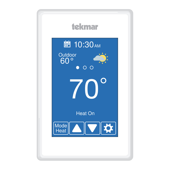
Page 14: User Interface
User Interface After 60 seconds of inactivity, the thermostat home screen displays only the time and the temperature. Go to schedule Current time Swipe to view: • Weather • Outdoor temperature • Floor temperature • Heat To setting • Cool To setting Current temperature • Relative Humidity Equipment operation Humidifier or Heat, Cool and Fan On Dehumidifer operation Change operating mode Go to settings Mode MENU SELECTION Emergency Heat AWAY SCHEDULE Heat DISPLAY TIME Touch or to Cool adjust temperatures Auto Heat-Cool WIFI... -
Page 15: User Settings
User Settings - - --- -- --- - - - - - - - - - - - ----- - - - - - - - - - - - - - - - - - - - - - - - - - - - - - - - - - - - - - - - --- -- --- - - - - - - - - - - - ----- - - - - - - - - - - - - - - - - - - - - - - - - - - - - - - - - - - - - - Away Use the Away setting to... -
Page 16: Display
- -- -- -- - ----- - ----- - - - - - --- - - - - - - - - - - - - - - - - - - - - - - - - - - - - - - - - - - - -- -- -- - ----- - ----- - - - - - --- - - - - - - - - - - - - - - - - - - - - - - - - - - - - - - - - - - Display Setting... -
Page 17: Time
- - - -- -- -- -- - - - - -- - - - - ----- - - - - - - - - - - - - - - - - - - - - - - - - - - - - - - - - - - - - - - - - - -- -- -- -- - - - - -- - - - - ----- - - - - - - - - - - - - - - - - - - - - - - - - - - - - - - - - - - - - - - Time When connected to the Internet, the time can be set automatically. -
Page 18: Wifi
- - - -- -- -- -- - - - - -- - - - - ----- - - - - - - - - - - - - - - - - - - - - - - - - - - - - - - - - - - - - - - WiFi Before using the WiFi features of this product, you must accept the Terms of Use, as amended from time to time and available at Watts.com/terms-of-use. If you do not accept these terms, this product can still be used without WiFi features. The thermostat includes a step by step tutorial to setup the WiFi connection. -
Page 19: Wifi And Connectivity Troubleshooting
• The router has DHCP enabled with enough available addresses for all Internet devices. • The router firewall is not blocking the outbound UDP or TCP ports: 53, 123, (1) WiFi Signal Strength 443, 8883. • The WiFi signal must measure between 0 • The router firewall is not blocking and -69 dB to have a reliable connection connections to *.azure-devices.net to the Watts cloud. • The router firewall is not blocking the • A WiFi extender is recommended to be thermostat based upon a MAC filter list. installed if the WiFi signal is between -70 to -100 dB. Network Troubleshooting (2) Internet Connected • tekmar provides free access to a network troubleshooting tool called RouteThis • The WiFi information screen will show Helps. -
Page 20: Installer Settings
Installer Settings - - --- -- -- - - - - ---- - - - - - ---- - - - - - - - - - - - - - - - - - - - - - - - - - - - - - - - - - - - - - - - --- -- -- - - - - ---- - - - - - ---- - - - - - - - - - - - - - - - - - - - - - - - - - - - - - - - - - - - - - Setup The Setup menu contains seven sub-menus that determine... -
Page 21: Setup - Temp
-- --- - - - - - ---- - - - - - --- - - - - - - - - - - - - - - - - - - - - - - - - - - - - - - - - - - -- --- - - - - - ---- - - - - - --- - - - - - - - - - - - - - - - - - - - - - - - - - - - - - - - - - - Setup - Temp Setting... -
Page 22: Setup - Sensors
---- - - - - ----- - - - - - -- - - - - - - - - - - - - - - - - - - - - - - - - - - - - - - - - - ---- - - - - ----- - - - - - -- - - - - - - - - - - - - - - - - - - - - - - - - - - - - - - - - - Setup - Sensors Setting... -
Page 23: Setup - Alerts
- - - - ---- - - - - - ---- - - - - - - - - - - - - - - - - - - - - - - - - - - - - - - - - - - - - - - - - - - ---- - - - - - ---- - - - - - - - - - - - - - - - - - - - - - - - - - - - - - - - - - - - - - - Setup - Alerts Setting... -
Page 24: Setup - Relays
- --- - - - - - ---- - - - - - - - - - - - - - - - - - - - - - - - - - - - - - - - - - - - - --- - - - - - ---- - - - - - - - - - - - - - - - - - - - - - - - - - - - - - - - - - - - Setup - Relays (1 of 3) Setting... - Page 25 - --- - - - - ----- - - - - - - - - - - - - - - - - - - - - - - - - - - - - - - - - - - - - --- - - - - ----- - - - - - - - - - - - - - - - - - - - - - - - - - - - - - - - - - - - Setup - Relays (2 of 3) Setting...
- Page 26 - - - - - - ----- - - - - - - - - - - - - - - - - - - - - - - - - - - - - - - - - - - - - - - - - - - - ----- - - - - - - - - - - - - - - - - - - - - - - - - - - - - - - - - - - - - - Setup - Relays (3 of 3) Setting...
-
Page 27: Setup - Humidity
---- - - ---- - - - - - ---- - - - - - - - - - - - - - - - - - - - - - - - - - - - - - - - - - - ---- - - ---- - - - - - ---- - - - - - - - - - - - - - - - - - - - - - - - - - - - - - - - - - - Setup - Humidity Humidity... -
Page 28: Tekmar Connect Web And Mobile App
--- - - - - ----- - - - - - - - - - - - - - - - - - - - - - - - - - - - - - - - - - - Add Thermostat to App Sign In REGISTRATION To finish registering your thermostat, enter the code displayed below in the Watts Home mobile app. 12345678 The registration code will expire in 30:00 minutes. Create Account Step 1 Step 2 Step 3 Create a new account. Then... - Page 29 - - ----- - - - - - ---- - - - - - - - - - - - - - - - - - - - - - - - - - - - - - - - - - - - - - - - - - ----- - - - - - ---- - - - - - - - - - - - - - - - - - - - - - - - - - - - - - - - - - - - - - - - Using the App Settings...
-
Page 30: Error Messages
Error Messages When an error occurs an email notification will be sent to the registered mobile account owner. Description MEMORY ERROR The thermostat memory settings are corrupted. To clear, load the factory defaults in the Toolbox menu. The thermostat will not operate any heating or cooling equipment while this error message is present. INTERNAL ROOM SENSOR FAULT Due to an open or short circuit, the thermostat is unable to read the internal room temperature sensor. If sensor 1, 2 or 3 is set to room the thermostat continues to operate, otherwise operation stops. The error cannot be field repaired. Contact your tekmar sales representative for warranty or repair procedures. INTERNAL HUMIDITY SENSOR FAULT Due to an open or short circuit, the thermostat is unable to read the internal humidity sensor. The thermostat stops controlling the humidifier or dehumidifier unless an external humidity sensor is installed on Sensor 3. The error cannot be field repaired. Contact your tekmar sales representative for warranty or repair procedures. SENSOR 1 FAULT Due to an open or short circuit, the thermostat is unable to read the sensor wired to S1 and Com. The thermostat stops normal operation if sensor 1 is the only active room or floor sensor or if a floor maximum temperature has been set. Check the auxiliary sensor wire for short circuits according to the sensor installa- tion manual. It may be necessary to replace the auxiliary sensor. Once the error has been corrected, the error message automatically clears. SENSOR 2 FAULT Due to an open or short circuit, the thermostat is unable to read the sensor wired to S2 and Com. The thermostat stops normal operation if sensor 2 is the only active room or floor sensor or if a floor maximum temperature has been set. - Page 31 Description INTERNET UNAVAILABLE The thermostat has a WiFi connection to the router but is unable to communicate to the internet. Steps to clear the error include: 1) power off and on the router, 2) power off and on the thermostat. ROOM HOT WARNING The room temperature is above the Room Hot Warning setting in the Alerts menu. The warning will automatically clear once the room temperature falls below the setting. ROOM COLD WARNING The room temperature is below the Room Cold Warning setting in the Alerts menu. The warning will automatically clear once the room temperature rises above the setting. LOW HUMIDITY WARNING The relative humidity is below the Low Humidity Warning setting in the Alerts menu. The warning will automatically clear once the relative humidity rises above the setting. HIGH HUMIDITY WARNING The relative humidity is above the High Humidity Warning setting in the Alerts menu. The warning will automatically clear once the relative humidity falls below the setting. AUXILIARY HEAT RUN TIME WARNING The auxiliary heat has been operating continuously longer than the Aux Heat Run Time Warning setting in the Alerts menu. The error clears when the auxiliary heat turns off. There may be problem with your heat pump. Contact your heating professional for service. CHANGE AIR FILTER WARNING The fan run time has exceeded the Change Air Filter setting in the Alerts menu and requires replacement. To clear the warning, press the Air Filter Replaced button.
- Page 32 Page intentionally left blank 32 of 36...
- Page 33 Page intentionally left blank 33 of 36...
- Page 34 Page intentionally left blank 34 of 36...
-
Page 35: Technical Data
Technical Data WiFi Thermostat 563 Conventional 2H/2C or Heat Pump 4H/2C Literature 563_C, 563_D, 563_J, 563_U Control Microprocessor control. This is not a safety (limit) control. Packaged weight 0.7 lb. (300 g) Dimensions 4-5/8" H x 3" W x 15/16" D (118 x 76 x 24 mm) Display 3.5" color touchscreen Enclosure White PVC plastic, NEMA Type 1 Approvals Meets Class B: ICES & FCC Part 15 Indoor use only, 32 to 122°F (0 to 50°C), RH ≤90% non- Ambient conditions condensing Environmental Do not use in presence of ammonia (animal barns). Power supply 15 to 30 V (ac/dc), 2 VA, Class 2 Relays 30 V (ac/dc), 2 A, Class 2 circuits Humidity sensor 0 to 90% ±4% RH Temperature sensor NTC thermistor, 10 kΩ @ 77°F (25°C ±0.2°C) ß=3892 – Included None – Optional tekmar type # 070, 072, 073, 076, 077, 079, 084, 086, 087 Communications... -
Page 36: Limited Warranty
Warranty Limited Warranty The liability of tekmar under this Any representations or warranties about the Products warranty is limited. The Purchaser, by taking receipt made by Purchaser to its customers which are different of any tekmar product (“Product”), acknowledges from or in excess of the tekmar Limited Warranty are the terms of the Limited Warranty in effect at the the Purchaser’s sole responsibility and obligation.
Need help?
Do you have a question about the tekmar 563 and is the answer not in the manual?
Questions and answers