Watts tekmar 562 Manual
Wifi thermostat
Hide thumbs
Also See for tekmar 562:
- User manual (12 pages) ,
- User manual (8 pages) ,
- User manual (9 pages)
Table of Contents
Advertisement
Quick Links
Installation, Operation and Maintenance
WiFi Thermostat 562
Works with the
Watts
®
Home Mobile App
Compatible With
• 2-stage heating, 1-stage cooling and fan
• Supports optional floor sensor for radiant floor heating applications
WARNING
!
Please read carefully before proceeding with
installation. Your failure to follow any attached
instructions or operating parameters may lead to the
product's failure.
Keep this Manual for future reference.
IOM-T-562
Advertisement
Table of Contents

Related Manuals for Watts tekmar 562


Summary of Contents for Watts tekmar 562
- Page 1 IOM-T-562 Installation, Operation and Maintenance WiFi Thermostat 562 Works with the Watts ® Home Mobile App Compatible With • 2-stage heating, 1-stage cooling and fan • Supports optional floor sensor for radiant floor heating applications WARNING Please read carefully before proceeding with installation. Your failure to follow any attached instructions or operating parameters may lead to the product’s failure.
-
Page 2: Table Of Contents
Table of Contents Important Safety Information ..................3 Installation ......................4 Preparation ......................4 Removing The Thermostat Base ...............4 Mounting The Thermostat ..................5 Relay Power Jumper ..................5 Application 562-1 ....................6 Application 562-2 ....................7 Application 562-3 ....................8 Application 562-4 ....................9 Sequence of Operation ..................10 Heating Operation .................... 10 Cooling Operation .................... 10 User Interface ....................... 11 User Settings ......................12 Away ........................ 12 Schedule ......................12 Display ......................13 Time ......................... 14 Fan ........................ -
Page 3: Important Safety Information
Important Safety Information It is your responsibility to ensure that this thermostat is safely installed according to all applicable codes and standards. tekmar is not responsible for damages resulting ® from improper installation and/or maintenance. This is a safety-alert symbol. The safety alert symbol is shown alone or used with a signal word (DANGER, WARNING, or CAUTION), a pictorial and/or a safety message to identify hazards. When you see this symbol alone or with a signal word on your equipment or in this Manual, be alert to the potential for death or serious personal injury. This pictorial alerts you to electricity, electrocution, and shock hazards. This symbol identifies hazards which, if not avoided, could result in death or serious injury. This symbol identifies hazards which, if not avoided, could result in minor or moderate injury. This symbol identifies practices, actions, or failure to act which could result in property damage or damage to the equipment. Read Manual and all product labels BEFORE using the equipment. Do not use unless you know the safe and proper operation of this equipment. Keep this Manual available for easy access by all users. Replacement Manuals are available at tekmarControls.com • It is the installer's responsibility to ensure that this thermostat is safely installed ac- cording to all applicable codes and standards. • Improper installation and operation of this thermostat could result in damage to the equipment and possibly even personal injury or death. • This thermostat is not intended for use as a primary limit control. Other controls that are intended and certified as safety limits must be placed into the control circuit. Do not attempt to service the thermostat. There are no user serviceable parts inside the thermostat. Attempting to do so voids warranty. IOM-T-562 2215 © 2022 tekmar... -
Page 4: Installation
Installation Preparation Tools Required • Wire stripper • Drill (for wall anchor) • tekmar or jeweler screwdriver • 3/16" drill bit (for wall anchor) • Phillips head screwdriver Materials Required • 18 AWG LVT Solid Wire (Low Voltage Connections) Installation Location Consider the following: • Interior Wall. • Keep dry. Avoid potential leakage onto the control. • Relative Humidity less than 90%. Non-condensing environment. • No exposure to extreme temperatures beyond 32-122°F (0-50°C). • No draft, direct sun, or other cause for inaccurate temperature readings. • Away from equipment, appliances, or other sources of electrical interference. • Easy access for wiring, viewing, and adjusting the display screen. • Approximately 5 feet (1.5 m) off the finished floor. • The maximum length of wire is 500 feet (150 m). • Strip wire to 3/8" (10 mm) for all terminal connections. • Use standard 8 conductor, 18 AWG wire. -
Page 5: Mounting The Thermostat
Mounting the Thermostat To prevent the risk of personal injury and/or death, make sure power is not applied to the thermostat until it is fully installed and ready for final testing. All work must be done with power to the circuit being worked on turned off. Please be aware local codes may require this thermostat to be installed or connected by an electrician. Stud Thermostat Base Thermostat Front Switch " (83 mm) Thermostat Front Wall Thermostat Stud Base Relay Power Jumpers AWAY The thermostat includes three relay power jumper connectors located below the wiring hole. • Set Jumper J1 to On to connect power R J1 J2 J3 to the Rh1 terminal. RELAY POWER JUMPER • Set Jumper J2 to On to connect power R to the Rh2 wiring terminal. -
Page 6: Application 562-1
Application 562-1 The WiFi Thermostat 562 operates a one or two-stage furnace for heating and an air conditioner for cooling. Mechanical Legend C1 = Air Conditioner F1 = Furnace T1 = WiFi Thermostat 562 Electrical Thermostat AWAY jumpers: WiFi Thermostat 562 J1 = On Furnace Terminals J2 = On J3 = On J1 J2 J3 AWAY RELAY POWER JUMPER IOM-T-562 2215 © 2022 tekmar... -
Page 7: Application 562-2
Application 562-2 The WiFi Thermostat 562 operates a first stage radiant floor and a second stage furnace for heating, and an air conditioner for cooling. Mechanical Legend F1 = Furnace S1 = Optional Floor Sensor 079 B1 = Boiler PS = System Pump S2 = Optional Indoor Sensor 084 BP = Boiler Pump T1 = WiFi Thermostat 562 ZVC1 = Zone Valve Control 304V, 306V C1 = Air Conditioner V1 = Zone Valve ZVC1 Electrical AWAY Thermostat AWAY jumpers: ZVC1 J1 = On J2 = Off J3 = Off WiFi Thermostat 562 J1 J2 J3 RELAY Furnace POWER JUMPER Terminals AWAY IOM-T-562 2215 ©... -
Page 8: Application 562-3
Application 562-3 The WiFi Thermostat 562 operates a first stage radiant floor and a second stage fan coil for heating, and an air conditioner for cooling. Mechanical Legend F1 = Fan Coil T1 = WiFi Thermostat 562 B1 = Boiler PS = System Pump V1 = Radiant Zone Valve BP = Boiler Pump S1 = Optional Floor Sensor 079 V2 = Fan Coil Zone Valve C1 = Air Conditioner S2 = Optional Indoor Sensor 084 ZVC1 = Zone Valve Control 304V, 306V ZVC1 Electrical AWAY Thermostat Handling ZVC1 Unit jumpers: AWAY Terminals J1 = On J2 = Off J3 = Off WiFi Thermostat 562 J1 J2 J3 RELAY POWER JUMPER AWAY IOM-T-562 2215 ©... -
Page 9: Application 562-4
Application 562-4 The WiFi Thermostat 562 operates a first stage baseboard/radiator and a second stage fan coil for heating, and an air conditioner for cooling. Mechanical Legend F1 = Fan Coil T1 = WiFi Thermostat 562 B1 = Boiler PS = System Pump V1 = Radiant Zone Valve BP = Boiler Pump S1 = Optional Floor Sensor 079 V2 = Fan Coil Zone Valve C1 = Air Conditioner S2 = Optional Indoor Sensor 084 ZVC1 = Zone Valve Control 304V, 306V ZVC1 Electrical AWAY Handling ZVC1 Thermostat Unit AWAY jumpers: Terminals J1 = On J2 = Off J3 = Off WiFi Thermostat 562 J1 J2 J3 RELAY POWER JUMPER AWAY IOM-T-562 2215 ©... -
Page 10: Sequence Of Operation
Sequence of Operation Heating Operation The heating setpoint can be set from 40 to 95°F (4.5 to 35°C). The Heat On symbol is shown on the display when the thermostat is heating. Heating for freeze protection is provided whenever the air or floor temperature falls below 40°F (4.5°C), regardless of operating mode. Regular Heating W1 relay is on when the air temperature falls 1.5°F (1°C) below the Heat To setting. When the temperature reaches the Heat To setting, the relay turns off. The W2 relay turns on based on settings selected in the Setup menu. W2 turns off when the air temperature is 0.5°F (0.25°C) below the Heat To setting. Radiant Floor Heating When Radiant Floor Heating is selected in the setup menu, the W1 relay operates using Pulse Width Modulation. This improves comfort for radiant systems with high mass floors. • 100% on time at Heat To setting -1.5°F • 50% on time at Heat To setting • 0% on time at Heat To setting + 1.5°F Room Sensor and Averaging The thermostat can measure room temperature between -46 to 212°F (-43 to 100°C). The room temperature can be measured using a combination of the built-in and auxiliary sensors. • Built-in room sensor only • Built-in room sensor with auxiliary room sensor(s) (temperature is averaged) • Auxiliary room sensor only Floor Sensor for Radiant Floor Heating If a floor sensor is connected, floor minimum and maximum settings are available. For a combination of air and floor temperature control, leave the internal air sensor on in the setup menu. A floor minimum can be used to prevent a fast drop in temperature caused by receding... -
Page 11: User Interface
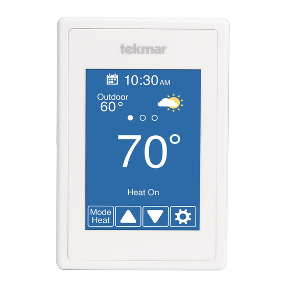
User Interface After 60 seconds of inactivity, the thermostat home screen displays only the time and the temperature. Go to schedule Current time Swipe to view: • Weather • Outdoor temperature Current temperature • Floor temperature • Heat To setting Equipment operation • Cool To setting (Heat or Cool On) Change operating mode Go to settings Mode MENU SELECTION Heat AWAY SCHEDULE Cool DISPLAY TIME Touch or to Auto Heat-Cool adjust temperatures WIFI SETUP Select either Heat To or Cool To Temperature Adjustment WIFI: Connected... -
Page 12: User Settings
User Settings Away Use the Away setting to • Selecting the Away Home / Away save energy when the setting on a thermostat or the mobile app will affect building is unoccupied all devices linked to that location through the app. Operates normally At Home • The Away temperature can Operates using the Away Away be adjusted in the Setup / temperature selected in Temps menu. the Setup menu Save Info Schedule Go to the next group Schedule Current group of of program days. program days. Mon Tue Wed Thu Fri Wake 6:00 AM 70°... -
Page 13: Display
Display Setting Range Default TEMPERATURE UNITS °F or °C °F Select °F or °C. ENERGY USE 0 to 24 (daily) View the number of hours the heating or cooling has 0 hours 0 to 744 (monthly) operated either daily or monthly. Energy Use Daily Usage Today 0 hrs 0 hrs View each day's run Yesterday 0 hrs 0 hrs 0 hrs 0 hrs time for both heating 0 hrs 0 hrs and cooling. 0 hrs 0 hrs 0 hrs... -
Page 14: Time
Time When connected to the Internet, the time can be set TIME & DATE automatically. 2019 The time and date can be manually set by highlighting a field and then using the or buttons. OPTIONS Choose from the time options listed below. Setting Range Default TIME FORMAT 12 or 24 hour 12 hour Select the time format. TIME SOURCE If Internet is available, the time source can Automatic, Manual Auto be either automatically or manually set. Hawaii, Alaska, Pacific, TIME ZONE Mountain, Central, Eastern, Eastern Select the local time zone. Atlantic, Newfoundland DAYLIGHT SAVING TIME Off, On Select the brightness when not in use. Incorrectly setting the time and date manually may prevent the thermostat from communicating to the mobile app. Automatic time source is recommended when using an Internet connection. -
Page 15: Wifi
WiFi Before using the WiFi features of this product, you must accept the Terms of Use, as amended from time to time and available at Watts.com/terms-of-use. If you do not accept these terms, this product can still be used without WiFi features. The thermostat includes a step by step tutorial to setup the WiFi connection. Tutorial WIFI NETWORK SSID Before first using WiFi features Select a network of this product, you must accept from the list: the Terms of Use available at https://www.watts.com/terms- Your House of-use by pressing AGREE below. -
Page 16: Wifi And Connectivity Troubleshooting
• The router is using WPA2-Personal security. • The router has DHCP enabled with enough available addresses for all Internet devices. (1) WiFi Signal Strength • The router firewall is not blocking the • The WiFi signal must measure between 0 outbound UDP or TCP ports: 53, 123, and -69 dB to have a reliable connection 443, 8883. to the Watts cloud. • The router firewall is not blocking • A WiFi extender is recommended to be connections to *.azure-devices.net installed if the WiFi signal is between -70 • The router firewall is not blocking the to -100 dB. thermostat based upon a MAC filter list. (2) Internet Connected Network Troubleshooting • The WiFi information screen will show • tekmar provides free access to a network... -
Page 17: Installer Settings
Installer Settings Setup The Setup menu contains five sub-menus that determine SETUP MENU how the thermostat operates. The Access Level setting in the Toolbox menu TOOLBOX TEMP determines how many settings are available to the user. SENSORS ALERTS Press back to return to RELAYS the main Settings menu. Setup - Toolbox Setting Range Default ERROR Displays any error messages. ACCESS LEVEL User, Select between user and installer access levels. User Installer Installer access level restricts access in the Setup Menu. WWSD, STATUS CWSD, The current status of warm weather shut down, cold W1, W2, weather shut down and each of the relays. Y1, G1 SOFTWARE VERSION J1255A Display the software version. -
Page 18: Setup - Temp
Setup - Temp Setting Range Default Screen Page 1 Off, 40 to 95°F HEAT TO AWAY Select the heating temperature when away. Off, 4.5 to 35.0°C Off, 40 to 95°F HEAT TO MIN LIMIT Select the minimum heating temperature limit. Off, 4.5 to 35.0°C Off, 40 to 95°F HEAT TO MAX LIMIT Select the maximum heating temperature limit. Off, 4.5 to 35.0°C Off, 45 to 100°F COOL TO AWAY Select the cooling temperature when away. Off, 7.0 to 38.0°C Off, 45 to 100°F COOL TO MIN LIMIT Select the minimum cooling temperature limit. -
Page 19: Setup - Sensors
Setup - Sensors Setting Range Default SENSOR 1 Off, Select the type of sensor connected to S1 and Com Room, wiring terminals. Floor Off, SENSOR 2 Room, Select the type of sensor connected to S2 and Com Floor, wiring terminals. Outdoor INTERNAL ROOM SENSOR Off, Select if the internal room temperature sensor is on or off. Only available when Sensor 1 or 2 is set to read a room or floor sensor. Off, ROOM OFFSET Manual offset correction of the room temperature -5 to +5°F measurement. -3.0 to 3.0°C Setup - Alerts Setting Range Default ROOM HOT WARNING Off, 40 to 100°F... -
Page 20: Setup - Relays
Setup - Relays Setting Range Default EQUIPMENT 1 Heat/1 Cool, 1Heat/1 Select the number states of the heating and cooling 2 Heat/1 Cool Cool equipment. RADIANT FLOOR HEATING No, Select if the first stage W1 heats a radiant floor. W2 DIFFERENTIAL 2 to 10°F 2°F Select when the second stage W2 heating turns on. 1.0 to 5.5°C 1.0°C Turn on point is the heat to minus the differential. W2 DELAY Select the time delay when the second stage W2 0 to 180 heating turns on. The time starts counting after the W1 minutes minute relay is turned on. Y MIN RUN TIME Select the minimum time the cooling compressor must 0:30 to 10:00 2:00 run before shutting off. This helps prevent compressor minutes... -
Page 21: Error Messages
Error Messages When an error occurs an email notification will be sent to the registered tekmar Connect mobile or web app account owner. Description MEMORY ERROR The thermostat memory settings are corrupted. To clear, load the factory defaults in the Toolbox menu. The thermostat will not operate any heating or cooling equipment while this error message is present. INTERNAL ROOM SENSOR FAULT Due to an open or short circuit, the thermostat is unable to read the internal room temperature sensor. If sensor 1 or 2 is set to room the thermostat continues to operate, otherwise operation stops. The error cannot be field repaired. Contact your tekmar sales representative for warranty or repair procedures. SENSOR 1 FAULT Due to an open or short circuit, the thermostat is unable to read the sensor wired to S1 and Com. The thermostat stops normal operation if sensor 1 is the only active room or floor sensor or if a floor maximum temperature has been set. Check the auxiliary sensor wire for short circuits according to the sensor installa- tion manual. It may be necessary to replace the auxiliary sensor. Once the error has been corrected, the error message automatically clears. SENSOR 2 FAULT Due to an open or short circuit, the thermostat is unable to read the sensor wired to S2 and Com. The thermostat stops normal operation if sensor 2 is the only active room or floor sensor or if a floor maximum temperature has been set. Check the auxiliary sensor wire for short circuits according to the sensor installa- tion manual. It may be necessary to replace the auxiliary sensor. Once the error has been corrected, the error message automatically clears. ROOM HOT WARNING The room temperature is above the Room Hot Warning setting in the Alerts menu. The warning will automatically clear once the room temperature falls below the setting. -
Page 22: Technical Data
Technical Data WiFi Thermostat 562 Two Stage Heat, One Stage Cool, Fan Literature 562_C, 562_D, 562_J, 562_U Control Microprocessor control. This is not a safety (limit) control. Packaged weight 0.7 lb. (300 g) Dimensions 4-5/8" H x 3" W x 15/16" D (118 x 76 x 24 mm) Enclosure White PVC plastic, NEMA Type 1 Approvals Meets Class B: ICES & FCC Part 15 Indoor use only, 32 to 122°F (0 to 50°C), RH ≤90% non- Ambient conditions condensing Power supply 15 to 30 V (ac/dc), 2 VA standby, Class 2 Relays 30 V (ac/dc), 2 A, Class 2 circuits Sensor NTC thermistor, 10 kΩ @ 77°F (25°C ±0.2°C) ß=3892 – Included None – Optional tekmar type # 070, 072, 073, 076, 077, 079, 084 Communications WiFi 802.11n, 2.4 GHz, WPA2 encryption Mobile app Apple iOS 12 or higher, Android 10 or higher IOM-T-562 2215 ©... - Page 23 Notes _ _ _ _ _ _ _ _ _ _ _ _ _ _ _ _ _ _ _ _ _ _ _ _ _ _ _ _ _ _ _ _ _ _ _ _ _ _ _ _ _ _ _ _ _ _ _ _ _ _ _ _ _ _ _ _ _ _ _ _ _ _ _ _ _ _ _ _ _ _ _ _ _ _ _ _ _ _ _ _ _ _ _ _ _ _ _ _ _ _ _ _ _ _ _ _ _ _ _ _ _ _ _ _ _ _ _ _ _ _ _ _ _ _ _ _ _ _ _ _ _ _ _ _ _ _ _ _ _ _ _ _ _ _ _ _ _ _ _ _ _ _ _ _ _ _ _ _ _ _ _ _ _ _ _ _ _ _ _ _ _ _ _ _ _ _ _ _ _ _ _ _ _ _ _ _ _ _ _ _ _ _ _ _ _ _ _ _ _ _ _ _ _ _ _ _ _ _ _ _ _ _ _ _ _ _ _ _ _ _ _ _ _ _ _ _ _ _ _ _ _ _ _ _ _ _ _ _ _ _ _ _ _ _ _ _ _ _ _ _ _ _ _ _ _ _ _ _ _ _ _ _ _ _ _ _ _ _ _ _ _ _ _ _ _ _ _ _ _ _ _ _ _ _ _ _ _ _ _ _ _ _ _ _ _ _ _ _ _ _ _ _ _ _ _ _ _ _ _ _ _ _ _ _ _ _ _ _ _ _ _ _ _ _ _ _ _ _ _ _ _ _ _ _ _ _ _ _ _ _ _ _ _ _ _ _ _ _ _ _ _ _ _ _ _ _ _ _ _ _ _ _ _ _ _ _ _ _ _ _ _ _ _ _ _ _ _ _ _ _ _ _ _ _ _ _ _ _ _ _ _ _ _ _ _ _ _ _ _ _ _ _ _ _ _ _ _ _ _ _ _ _ _ _ _ _ _ _ _ _ _ _ _ _ _ _ _ _ _ _ _ _ _ _ _ _ _ _ _ _ _ _ _ _ _ _ _ _ _ _ _ _ _ _ _ _ _ _ _ _ _ _ _ _ _ _ _ _ _ _ _ _ _ _ _ _ _ _ _ _ _ _ _ _ _ _ _ _ _ _ _ _ _ _ _ _ _ _ _ _ _ _ _ _ _ _ _ _ _ _ _ _ _ _ _ _ _ _ _ _ _ _ _ _ _ _ _ _ _ _ _ _ _ _ _ _ _ _ _ _ _ _ _ _ _ _...
-
Page 24: Limited Warranty And Product Return Procedure
Warranty Limited Warranty The liability of tekmar under this Any representations or warranties about the Products warranty is limited. The Purchaser, by taking receipt made by Purchaser to its customers which are different of any tekmar product (“Product”), acknowledges from or in excess of the tekmar Limited Warranty are the terms of the Limited Warranty in effect at the the Purchaser’s sole responsibility and obligation.
Need help?
Do you have a question about the tekmar 562 and is the answer not in the manual?
Questions and answers