
Related Manuals for Watts tekmar 560


Summary of Contents for Watts tekmar 560
- Page 1 IOM-T-560 Installation Manual Thermostat 560 Compatible With • 1-stage heating • Supports optional floor sensor for radiant floor heating applications...
-
Page 2: Table Of Contents
Table of Contents Important Safety Informati ........................3 Installation .............................4 Preparation ............................4 Removing The Thermostat Base ......................5 Mounting The Thermostat ........................5 Application 560-1 ..........................6 Application 560-2 ..........................7 Application 560-3 ..........................8 Application 560-4 ..........................9 Sequence of Operation ........................10 Heating Operation ..........................10 User Interface ............................11 User Settings............................12 Away ..............................12 Schedule ............................12... -
Page 3: Important Safety Informati
Important Safety Information It is your responsibility to ensure that this thermostat is safely installed according to all applicable codes and standards. tekmar is not responsible for damages resulting from improper installation and/ or maintenance. This is a safety-alert symbol. The safety alert symbol is shown alone or used with a signal word (DANGER, WARNING, or CAUTION), a pictorial and/or a safety message to identify hazards. -
Page 4: Installation
Installation Preparation Tools Required • Wire stripper • Drill (for wall anchor) • tekmar or jeweler screwdriver • 3/16" drill bit (for wall anchor) • Phillips head screwdriver Materials Required • 18 AWG LVT Solid Wire (Low Voltage Connections) Installation Location NOTICE Consider the following: •... -
Page 5: Removing The Thermostat Base
Removing The Thermostat Base While holding the base section in one hand, pull the lower half of the display front towards you to pivot it away from the base. Moving The Thermostat To prevent the risk of personal injury and/or death, make sure power is not applied to the thermostat until it is fully installed and ready for final testing. -
Page 6: Application 560-1
Application 560-1 The Thermostat 560 operates a radiant floor heating system. The thermostat uses the built-in air tem- perature sensor. Mechanical Legend B1 = Boiler BP = Boiler Pump PS = System Pump T1 = Thermostat 560 V1 = Zone Valve ZVC1 = Zone Valve Control 304V or 306V ZVC1 Electrical... -
Page 7: Application 560-2
Application 560-2 The Thermostat 560 operates a radiant floor heating system based upon the floor temperature sen- sor. The built-in air sensor is disabled. Mechanical Legend B1 = Boiler BP = Boiler Pump PS = System Pump T1 = Thermostat 560 S1 = Floor Sensor 079 V1 = Zone Valve ZVC1 = Zone Valve Control 304V or 306V... -
Page 8: Application 560-3
Application 560-3 Mechanical The Thermostat 560 operates a radiant floor heating system. The thermostat uses both air and floor temperature sensors. The air temperature sensor can be either built-in and/or external. Legend B1 = Boiler S1 = Floor Sensor 079 BP = Boiler Pump S2 = Optional Indoor Sensor 084 PS = System Pump... -
Page 9: Application 560-4
Application 560-4 Mechanical The Thermostat 560 operates a baseboard/radiator using an air temperature sensor. The air tempera- ture sensor can be either built-in and/or external. Legend B1 = Boiler S1 = Optional Indoor Sensor 084 BP = Boiler Pump V1 = Zone Valve PS = System Pump ZVC1 = Zone Valve Control 304V or 306V T1 = Thermostat 560... -
Page 10: Sequence Of Operation
Sequence of Operation Heating Operation The Heat On symbol is shown on the display when the thermostat is heating. Heating for freeze protection is provided whenever the air or floor temperature falls below 40°F (4.5°C), regardless of operating mode. Regular Heating W1 relay is on when the air temperature falls 1.5°F (1°C) below the Heat To setting. -
Page 11: User Interface
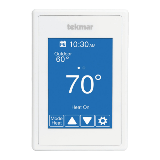
User Interface After 60 seconds of inactivity, the thermostat home screen displays only the time and the temperature. Go to schedule Current time Swipe to view: • Outdoor temperature • Floor temperature Current temperature • Heat To setting Equipment operation (Heat On) Go to settings Change operating mode... -
Page 12: User Settings
User Settings Away Use the Away setting to save Home / Away energy when the building is unoccupied Operates normally At Home • The Away temperature can Operates using the Away Away be adjusted in the Setup / temperature selected in the Temps menu. -
Page 13: Display
Display Setting Range Default Temperature units °F or °C °F Select °F or °C. ENERGY USE 0 to 24 (daily) 0 hours View the number of hours the heating or cooling has operated 0 to 744 (monthly) either daily or monthly. Daily Usage Today 0 hrs... -
Page 14: Time
Time TIME & DATE 2016 The time and date is manually set by highlighting a field and then using the buttons. OPTIONS Choose from the time options listed below. Setting Range Default TIME FORMAT 12 or 24 hour 12 hour Select the time format. -
Page 15: Installer Settings
Installer Settings Setup The Setup menu contains five sub-menus that determine SETUP MENU how the thermostat operates. The Access Level setting in the Toolbox menu deter- TOOLBOX TEMP mines how many settings are available to the user. SENSORS ALERTS Press back to return to RELAYS the main Settings menu. -
Page 16: Setup - Temp
Setup - Temp Setting Range Default Screen Page 1 FLOOR MIN Off, 40 to 95°F Select the floor temperature minimum. Applies when there Off, 4.5 to 35.0°C is both floor and an air sensors and when no schedule is set. FLOOR MIN - WAKE Off, 40 to 95°F Select the floor temperature while in the wake schedule. -
Page 17: Setup - Sensors
Setup - Sensors Setting Range Default SENSOR 1 Off, Room, Select the type of sensor connected to S1 and Com wiring Floor terminals. Off, SENSOR 2 Room, Select the type of sensor connected to S2 and Com wiring Floor, terminals. Outdoor INTERNAL ROOM SENSOR Off,... -
Page 18: Error Messages
Error Messages Error icon will appear on the home screen when an error is present. Description MEMORY ERROR The thermostat memory settings are corrupted. To clear, load the factory defaults in the Toolbox menu. The thermostat will not operate any heating equipment while this error message is present. INTERNAL ROOM SENSOR FAULT Due to an open or short circuit, the thermostat is unable to read the internal room temperature sen- sor. -
Page 19: Technical Data
Technical Data THERMOSTAT 560 ONE STAGE HEAT Literature ES-T-560, IOM-T-560, 560_J, UserManual-T-560 Control Microprocessor control. This is not a safety (limit) control. Packaged weight 0.6 lb. (270 g) Dimensions 4-5/8" H x 3" W x 15/16" D (118 x 76 x 24 mm) Enclosure White PVC plastic, NEMA Type 1 Approvals... -
Page 20: Limited Warranty And Product Return Procedure
Representative. Need help? Go to our website or contact us. watts.com/tekmar | tekmar.customerservice@wattswater.com | 1-800-438-3903 Tel: 1-800-438-3903 • Fax: (250) 984-0815 watts.com/tekmar ©2021 tekmar Control Systems Ltd.
Need help?
Do you have a question about the tekmar 560 and is the answer not in the manual?
Questions and answers