
Related Manuals for Haier HR18D2VAE


Summary of Contents for Haier HR18D2VAE
- Page 1 13 SEER 1.5 to 5.0 Tons HR18D2VAE HR24D2VAE HR30D2VAE HR36D2VAE HR42D1VAE HR48D1VAE HR60D1VAE No.0150505381 D...
- Page 2 ! WARNING These instructions are intended as an aid to qualified, licensed service personnel for proper installation, adjustment and operation of this unit. Read these instructions thoroughly before attempting installation or operation. Failure to follow these instructions may result in improper installation, adjustment, service or maintenance possibly resulting in fire, electrical shock, property damage, personal injury or death.
-
Page 3: Table Of Contents
Give this manual to the owner and explain its provisions. The owner should retain this manual for future reference. 2.NOMENCLATURE FOR MODEL NUMBER Brand symbol-H:Haier System type-C:Air conditioner;R:Heat pump Nominal capacity in (000) Btu/h SEER designation. D=13,E=14 Design series. -
Page 4: Specification
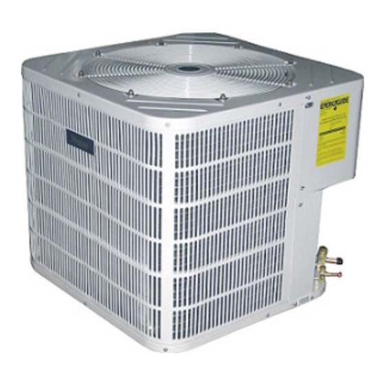
3.SPECIFICATION The dimensions for the condensing unit are illustrated in Figure 1. Physical and electrical specifications are provided in Table 1 for 13 SEER systems respectively. The Figure 2 show a schematic of a heat pump on the cooling cycle and the heating cycle. Table1: Model:HR18-36D2VAE HR42-60D1VAE... - Page 5 Figure 1 Table2: System Capacity cooling ARI data of indoor Cooling Capacity with different outdoor temperature Outdoor Indoor Indoor fan speed Capacity SEER HR18D2VAE HB2400VD2M20 18000 20340 19746 19080 18000 17730 17460 17190 16920 HR24D2VAE HB2400VD2M20 24000 27120 26328 25440...
- Page 6 Heat Pump Refrigerant Circuit Figure 2 Cooling DISCHARGE TEMP. SENSOR CHECK VALVE SERVICE PORT REVERSING VALVE SERVICE VALVE HIGH PRESSURE LOW PRESSURE SWITCH SWITCH ACCUMULATOR COMPRESSOR SERVICE PORT SERVICE PORT DEFROST SENSOR INDOOR COIL OUTDOOR COIL DRIER SERVICE VALVE DISTRIBUTOR DISTRIBUTOR Heating DISCHARGE TEMP.
-
Page 7: Unit Inspection
4.UNIT INSPECTION This product has been inspected at the factory and released to the transportation agency without known damage. Inspect exterior of carton for evidence of rough handling in shipment. Unpack carefully. If damage is found, report immediately to the transportation agency. 5.EQUIPMENT PROTECTION FROM ENVIRONMENT The metal parts of the unit may be subject to rust or corrosion in adverse environmental conditions. -
Page 8: Unit Clearances
Provide a level concrete slab. To prevent transmission of noise or vibration, slab should not be connected to building structure. Some sort of sound-absorbing material should be placed between the condenser and the slab. A good material to use is rubber and cork pad. For rooftop application, make sure the building construction can support the weight and that proper consideration is given to the weather-tight integrity of the roof. - Page 9 OUTDOOR UNIT ADDITIONAL SUCTION LINE PITCH SUCTION LINE TOWARD OUTDOOR OIL TRAP FOR EACH 20 FOOT UNIT 1/2" FOR EVERY 10' OF LINE RISE OF PIPE INDOOR UNIT ABOVE OR LEVEL TO OUTDOOR UNIT LIQUID LINE MAX. OUTDOOR UNIT SUCTION LINE OIL INDOOR UNIT TRAP WHEN INDOOR INDOOR UNIT...
- Page 10 Refrigerant Line Sizing Check the following table (Table 3) for correct suction and liquid line sizes for any combination of the unit size and the maximum refrigerant line length. Refrigerant Line Length (Ft) Unit Size Up to 25 26-50 51-75 (Ton) Seer Suction...
- Page 11 Replace the existing indoor unit fixed orifice with the orifice supplied with the outdoor unit. See table 4 for the fixed orifice size for each unit. Table 4 Fixed orifice size outdoor model indoor model orifice size HR18D2VAE HB2400VD2M20 HR24D2VAE HB2400VD2M20 HR30D2VAE HB3600VD2M20-T...
- Page 12 Evacuation All new installations must be evacuated to a deep vacuum in order that all noncondensible gases and moisture are removed prior to charging the system. Air in a system causes high condensing pressure, which increases power consumption and reduces performance. The presence of moisture in a system can render it inoperable in a very short time.
-
Page 14: System Startup
The condensing unit rating plate and the tables of "Physical and Electrical Specifications / Outdoor Units" (Table 1) provide pertinent data necessary for the selection of proper size electrical service and over-current protection devices. Table 6 provides data on the minimum copper wire size as a function of supply wire length and circuit ampacity. -
Page 15: Operation
11.If checking the unit on the heating cycle in the wintertime, when the outdoor coil is cold enough to actuate the defrost control, observe at least one defrost cycle to make sure the unit defrosts properly. 12.Check the refrigerant charge (see Instructions under "Charging the System"). 13.Replace service port caps. - Page 16 Table 7 Trouble-shooting guide Power off or loose electrical connection Make sure main switch is ON. Check and tighten all connections. Incorrect thermostat setting Set thermostat correctly No cooling/heating Defective contactor Check for 24V at contactor coil. Open circuit breaker of blown fuses Reset or replace Defective transformer Check wiring - Replace it.
- Page 17 HR18-36D2VAE HR42-60D1VAE...
Need help?
Do you have a question about the HR18D2VAE and is the answer not in the manual?
Questions and answers