Table of Contents
Advertisement
Central Air Conditioning
SERVICE MANUAL
●Features
Efficient performance and economical operation
Benchmark hermetic compressor design
Haier Hi-Efficiency aluminium fin and copper tube design
Compact design
Durable construction
Quick, easy installation and service
Heat pump, Value Series HR13-D2
Powder coated full metal jacket
Manual code: SYJS-014-07REV.0
Models
HR18D2VAR
HR24D2VAR
HR30D2VAR
HR36D2VAR
Edition: 2007-04-02
Advertisement
Table of Contents
Troubleshooting

Related Manuals for Haier HR18D2VAR


Summary of Contents for Haier HR18D2VAR
-
Page 1: Service Manual
HR24D2VAR HR30D2VAR HR36D2VAR ●Features Efficient performance and economical operation Benchmark hermetic compressor design Haier Hi-Efficiency aluminium fin and copper tube design Compact design Durable construction Quick, easy installation and service Heat pump, Value Series HR13-D2 Powder coated full metal jacket Manual code: SYJS-014-07REV.0... -
Page 2: Table Of Contents
Central Air Conditioning Model: Heat Pump, HR13-D2 CONTENTS 1. DESCRIPTION OF PRODUCTS & FEATURES……………………...3 2. PHYSICAL AND ELECTRICAL SPECIFICATIONS………………..5 3. SAFETY PRECAUTION…………………………………………….…...8 4. SYSTEM COMPONENTS AND FUNCTIONS ………………………..8 5. ELECTRICAL CONTROL DEVICES…………………………….……..10 6. APPLICATION…………………..……………………………………..…11 7. REFRIGERANT DIAGRAM ………………………………..…….……..13 8. INSTALLATION INSTRUCTIONS………………………..…………...13 9. -
Page 3: Description Of Products & Features
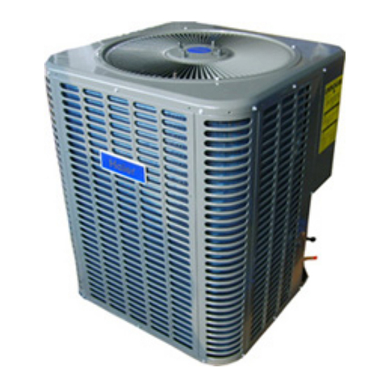
1.2 NOMENCLATURE FOR MODEL NUMBER Model number explanation---indoor unit Nominal Electric Electric Design Airflow Unit Efficiency Haier Blower unit capacity in Continuation heater Designation code series configuration Width(in.) (1000) Btu/h Y:575V-3Ph-60Hz;... - Page 4 Central Air Conditioning Model: Heat Pump, HR13-D2 CABINETS: Constructed of powder painted galvanized steel to provide a durable finish and protection for the outdoor coil. Fig.1-1 FAN GUARD AND MOTOR BRACKET: Welded powder coated guard with independent rod and band motor bracket, unit top has a deep draw fan venturi for efficient air flow.
-
Page 5: Physical And Electrical Specifications
Central Air Conditioning Model: Heat Pump, HR13-D2 2. PHYSICAL AND ELECTRICAL SPECIFICATIONS Specifications Subject to Change without Prior Notice Model Number HR18D2VAR HR24D2VAR HR30D2VAR HR36D2VAR Comments 1.5-Ton Outdoor HP 2-Ton Outdoor HP 2.5-Ton Outdoor HP 3-Ton Outdoor HP Model Status... - Page 6 Plastic mesh Optional Optional Optional Optional Features Lug. Galvanized Steel Cabinet Coil Design Haier Enhanced Coil Haier Enhanced Coil Haier Enhanced Coil Haier Enhanced Coil Fully Enclosed Motor Removable Top Grill Assembly Elevated Base Pan High and Low Pressure Switches...
- Page 7 26 7/8 Cubic Volume (Cu. Ft) 11.92 11.92 11.92 13.38 Warranty(Haier Brand Only) Parts Compressor Noise level dB(A) Notes: 1- 120-second fan delay for air handler 2- R-22 Charge for the outdoor unit with matching indoor unit and 25' line set.
-
Page 8: Safety Precaution
Central Air Conditioning Model: Heat Pump, HR13-D2 3. SAFETY PRECAUTIONS CAUTION : please read all instructions prior to installing, operating, maintaining or repairing the product. WARNING: THE MANUFACTURER’S WARRANTY DOES NOT COVER DAMAGE TO CAUSED BY THE USE OF ANSUTHORIZED COMPONENTS OR ACCESSORIES, THE USE OF SUCH UNAUTHORIZED COMPONENTS OR ACCESSORIES MAY ENDANGER LIFE AND PROPERTY. - Page 9 Central Air Conditioning Model: Heat Pump, HR13-D2 Both compressor types are protected internally against over-current and over-temperature conditions. Some scroll compressors have an additional thermostat mounted externally in series electrically with the contactor coil. FAN AND BLOWER MOTORS (Fig. 4-2 and Fig. 4-3) The outdoor component of split system contains an fan motor.
-
Page 10: Electrical Control Devices
Central Air Conditioning Model: Heat Pump, HR13-D2 REFRIGERANT CIRCUIT (Fig. 4-5) All 13SEER units outdoor coils are multi-circuit. Refrigerent gas or liquid is uniformly distributed to from 4 to 10 circuits to improve heat transfer and reduce capacity losses due to pressure drops. Fig.4-5 SERVICE VALVES There are two types of service valve used on these air conditioning units. -
Page 11: Application
Central Air Conditioning Model: Heat Pump, HR13-D2 RELAYS Relays provide a method for control switching. Relays may switch either low(24VAC) or line voltage. Generally relays used in air conditioning use 24VAC coils. Contact voltage may be either low or line voltage. COMPREESSOR CONTACTOR The coil uses 24 volts but the contacts carry line voltage .The heater contactor is a large relay, which controls the compressor and the outdoor fan operation. -
Page 12: Unit Dimensions
● Diffuser and return air grille location and sizing Unit Dimensions Model: HR18-36D2VAR Dimensions W(inch[mm]) D(inch[mm]) H(inch[mm]) Unit 24 1/4[616] 24 1/4[616] 26 7/8[683] HR18D2VAR Shipping 26 7/8[682] 26 7/8[682] 28 1/2[725] Unit 24 1/4[616] 24 1/4[616] 26 7/8[683] HR24D2VAR Shipping... -
Page 13: Refrigerant Diagram
Indoor (Installed in (placed in speed outdoor) package bag) HR18D2VAR HB2400VD1M20 HR24D2VAR HB2400VD1M20 HR30D2VAR HB3600VD1M22 HR36D2VAR HB3600VD1M22 Table 6-2 Piston size The air distribution system has the greatest effect. On the quality of the installation and the owner satisfaction, the duct system is totally in the responsibility of the contractor. These are numerous thchnical associations and reference that recommend correct procedures. - Page 14 Central Air Conditioning Model: Heat Pump, HR13-D2 Heat Pump Refrigerant Circuit Figure 7...
-
Page 15: Equipment Protection From Environment
Central Air Conditioning Model: Heat Pump, HR13-D2 This product is designed and manufactured to permit installation in accordance with National Codes. It is the installer's responsibility to install the product in accordance with National Codes and/or prevailing local codes and regulations. The manufacturer assumes no responsibility for equipment installed in violation of any codes or regulations. -
Page 16: Unit Clearances
Central Air Conditioning Model: Heat Pump, HR13-D2 Power supply and wiring. Consideration be given so that operating sounds will not disturb owner or neighbors. Location with no risk of combustible gas leakage. Location where natural water drainage does not collect around the unit. Location where roof runoff does not pour directly on the unit. -
Page 17: Refrigerant Piping
Central Air Conditioning Model: Heat Pump, HR13-D2 8.5 REFRIGERANT PIPING Properly sized and installed refrigerant piping is very important for the efficient operation of the air conditioning system. Note the following guidelines The total run, both vertical and horizontal, should be less than 50 feet or line size correction may be necessary. - Page 18 Central Air Conditioning Model: Heat Pump, HR13-D2 Liquid lines do not necessarily need insulation, however, if they are run in high ambient spaces such as kitchens, boiler rooms, hot attics or on the roof, then, they should be insulated as well. Make sure to use proper size copper tubing for the liquid line to prevent liquid refrigerant flashing.
-
Page 19: Charging The System
Central Air Conditioning Model: Heat Pump, HR13-D2 1.Tubing should be cut square. Make sure it is round and free of burrs at the connecting ends. Clean the tubing to prevent contamination from entering the system. 2.Make sure that both refrigerant shutoff valves at the outdoor unit are closed. 3.Push the tubing into the fitting until it stops. -
Page 20: Electrical Wiring
Central Air Conditioning Model: Heat Pump, HR13-D2 System Superheat Ambient Return Air Temperature ( ) ℉ Temperature At Condenser Inlet ℉ Table 8-2: System charging table by superheat 8.8 ELECTRICAL WIRING ! WARNING A means of strain relief must be installed to this appliance at the electrical service entrance. The interconnecting wires between indoor and outdoor units must be in accordance with the national electric code and all code regulations. - Page 21 Central Air Conditioning Model: Heat Pump, HR13-D2 Copper Wire Size - AWG (1% Voltage Drop) Supply Circuit Supply Wire Length - Ft Ampacity Table8-3: Minimum Wire Size Based on N.E.C. for 60 C Type Copper Conductors Below 100 Ampacity. The installer must be familiar with the location of the over-current protection, properly size for this this application and the proper procedure for disconnecting power service to the unit.
-
Page 22: System Startup
Central Air Conditioning Model: Heat Pump, HR13-D2 8.10.SYSTEM STARTUP 1.Turn thermostat to "OFF", turn on power supply at disconnect switch. 2.Turn temperature setting above the room temperature. 3.Turn fan switch to "ON". Indoor blower should run. Be sure it is running in the right direction. 4.Turn fan switch to "AUTO". -
Page 23: Maintenance Instructions
Central Air Conditioning Model: Heat Pump, HR13-D2 9.MAINTENANCE INSTRUCTIONS FILTERS WARNING: DISCONNECT MAIN ELECTRICAL POWER TO THE UNIT BEFORE ATTEMPTING ANY SERVICE OR MAINTENANCE. The air conditioning system operates must efficiently with clean air filters, check filters monthly to determine how frequently your filters need be cleaned. A new home require more frequent filter attention until dust and fibers from the construction is removed. - Page 24 Central Air Conditioning Model: Heat Pump, HR13-D2 of refrigerant into the air. Proper charging of refrigerant system may require removing some refrigerant when the system is overcharged. and is to be used by personnel with appropriate industry experience recover the excess refrigerant. Recovery means to collect the refrigerant in a special holding container.
- Page 25 Central Air Conditioning Model: Heat Pump, HR13-D2 OUTDOOR UNIT INSTALLATION ………….Unit level with proper clearances for air flow and service …………..Proper elevation of outdoor unit …………..Solid pad …………..Coil free from dirt and debris …………..Unit charged according to manufacturer’s instructions …………..No evidence of refrigerant leaks REFRIGERANT LINES ………….Proper length according to manufacturer’s instructions …………..Proper size according to manufacturer’s instructions...
- Page 26 Central Air Conditioning Model: Heat Pump, HR13-D2 Run capacitor Fig.10-2 Some compressors require the assistance of a hard start kit to start, it is urgest to consult the compressor manufactores recommendations for start kits. follow the manufactores installation information. WARNING:DISCONNECT ALL POWER TO THE OUTDOOR UNIT BEFORE BEGINNING THIS TEST .
- Page 27 Central Air Conditioning Model: Heat Pump, HR13-D2 characteristics. CONDENSER FAN BLADE LOCATION Dimension “A” will be from 2” to 4” depending on the unit model number. Be sure to check this dimension BEFORE removing the fan blade. Note: When parts combination results in motor /blade interference ,the fan blade should be located to provide 1/8”...
- Page 28 Central Air Conditioning Model: Heat Pump, HR13-D2 to suffers lack of dehumidify in cooling. insufficient air flow while cooling may result in coil freeze up, excessive dehumifification and lost capacity. Checking air flow is the most important diagonistics a service technican can perform. Instructions are rrovided to show how to measure pressure drop across the coil.
- Page 29 Central Air Conditioning Model: Heat Pump, HR13-D2 B. The ohm reading from the Start TERMINAL TO COMMON TERMINAL will be the middle ohm value measured between the terminals and be approximately 2.0 to 3.0 ohms The ohm reading from the Start TERMINAL TO Run terminal will be the highest ohm value of the three measurements and will be approximately the sum of the first two measurements.
- Page 30 Central Air Conditioning Model: Heat Pump, HR13-D2 After pump down and compressor stops, observe the suction pressure on the compound gauge. A. The suction pressure holds as steady pressure. this is a normal condition. B. Suction pressure rises above the stopping point, but then stops and holds steady. Some refrigerant finally evaporating in the coil, and registering on the gauge.
- Page 31 Central Air Conditioning Model: Heat Pump, HR13-D2 4. Remove the failed compressor. A. Unsolder the suction and discharge lines at the compressor stubs. B. Remove the compressor hold down bolts. C. Place the failed compressor on a smooth surface to remove the mounting grommets and sleeves for use with the new compressor .
-
Page 32: Troubleshooting Guide
Central Air Conditioning Model: Heat Pump, HR13-D2 7. Other Check Points A. Verify the operating voltage is within the specified range. B. Check that all wiring connections are tight. C. Verify that all fuses or circuit breakers are of the proper type and operational. D. - Page 33 Central Air Conditioning Model: Heat Pump, HR13-D2 Run or start capacitor defective Replace Loose connection Check and tighten all connections. Compressor stuck, grounded or open Wait for 2 hours for overload to reset. Condenser fan runs, motor winding, open internal overload Replace compressor if still open.
- Page 34 Central Air Conditioning Model: Heat Pump, HR13-D1 Electric control board and function for central air conditioner Heat pump control board 1. Failure code Note: 1/2 second flash sycle indicates problem indication. Failure indication: LED will flash for alarm. Flash frequency: 0.5 second on and 0.5 second off with a 2 seconds interval between flashes.
- Page 35 Central Air Conditioning Model: Heat Pump, HR13-D1 When LED is used as a status indicator, the following codes will be shown: 1.5 In defrost, the LED will flash 2 seconds on, 2 senconds off. 1.6 In the normal operation state and the compressor is running – outdoor PCB LED will be in the ON state. 1.7 In normal state, if compressor not running –...
- Page 36 Central Air Conditioning Model: Heat Pump, HR13-D1 3.2 Outdoor discharging temp. sensor: R80=50K±3%, B25/80=4450K±3%, with copper terminal 3.3 High pressure switch: N.C. type pressure switch, the open pressure: 435Psi / close pressure: 377Psi; (adjustable) 3.4 Low pressure switch: N.C. type pressure switch, the open pressure: 7.25Psi / close pressure: 21.75Psi;...
- Page 37 Central Air Conditioning Model: Heat Pump, HR13-D1 4.6 CN7 — — discharging temp. sensor connector; the discharging temp. sensor connected /disconnected failure: 30seconds later alarm; the failure can be resumable. When compressor is running, if the discharging temp. >248℉, compressor will stop; if the discharging temp.<203℉ for 3 minutes, compressor will run.
-
Page 38: Defrosting Operation
Central Air Conditioning Model: Heat Pump, HR13-D1 (The unit of temp. is 5. Defrosting operation ℉ 5.1 Defrosting procedure:SW1-1: OFF; SW1-2: OFF heat pump mode record Tp0 after compressor on for 8 min Check and reconnect Is Tp(pipe temp)< 35.6 for 10 sec 90 min >... - Page 39 Central Air Conditioning Model: Heat Pump, HR13-D1 5.3 Troubleshooting: does the unit work properly? does there show any default refer to other fault solution code ? does the dip switch at proper change the dip switch to right position position?(refer to wire diagram) check the resistance of pipe replace pipe sensor sensor,whether at normal...
-
Page 40: Heat Pump Wiring Diagram
CT once continuous on - 24VAC supplied to Y terminal of defrost control. Flash on/off - System in defrost operation. HR18D1VAR HR42D1VAR HR18D2VAR HR42D2VAR HR18E1VAR HR42E1VAR 1/2 + 1/2 1 flash - Pipe/coil sensor open or short circuit. HR24D1VAR... - Page 41 Central Air Conditioning Model: Heat Pump, HR13-D2 Sincere Forever Haier Group Haier Industrial Park, No.1, Haier Road 266101, Qingdao, China http://www.haier.com...
Need help?
Do you have a question about the HR18D2VAR and is the answer not in the manual?
Questions and answers