Table of Contents
Advertisement
Available languages
Available languages
perator's
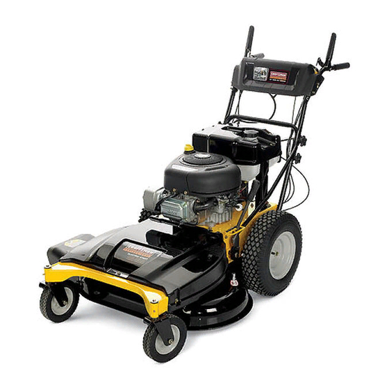
PROFESSIONAL
33-inch
Wide Cut Mower
Model No. 247.889980
For answers
to your questions
about
this product,
call 1-800-4MY=HOME.
CAUTION:
Before using this
product,
read this manual and
follow
all safety
rules and operating
instructions.
,
SAFETY
ASSEMBLY
OPERATION
MAINTENANCE
PARTS LIST
ESPANOL R 48
Sears, Roebuck and Co., Hoffman
Estates,
IL 60179, U.S.A.
Visit our website:
www.sears.com/craftsman
FormNo.769-04684A
(December 2 1,2009)
Advertisement
Table of Contents

Related Manuals for Craftsman 247.889980


Summary of Contents for Craftsman 247.889980
- Page 1 PROFESSIONAL 33-inch Wide Cut Mower Model No. 247.889980 For answers to your questions call 1-800-4MY=HOME. CAUTION: Before using this product, read this manual and follow all safety rules and operating instructions. Sears, Roebuck and Co., Hoffman Visit our website:...
- Page 2 Assembly ... Know your Lawn Mower ... Operation ... CRAFTSMAN Whenoperatedand maintained accordingto all suppliedinstructions, i f this CraftsmanProfessional p roductfails due to a defectin materialor workmanship withintwo years from thedateor purchase,call 1-800-4-MY-HOME® to arrangefor free repair(or replacementif repairproves impossible).
- Page 3 which,ifnot followed,couldendangerthe personal __IL his symbolpointsout important s afetyinstructions safetyand/or propertyof yourselfand others.Read and followall instructions in this manualbefore attemptingto operatethis machine.Failureto complywith these instructions may resultin personalinjury. W henyou seethis symbol, HEEDITS WARNING! Your Responsibility: Restrictthe useof this powermachineto personswhoread,understand,and followthe warningsand instruc- tions inthis manualand on the machine.
- Page 4 • If the equipmentshould startto vibrateabnormally,stop the engine and check immediately for the cause.Vibrationis generallya warningof trouble. • Shutthe engineoff andwait untilthe bladecomesto a completestop beforeremovingthe grass catcheror uncloggingthe chute. The cuttingblade continuesto rotatefor a fewseconds afterthe engine is shut off. Neverplace any part of the bodyinthe bladearea untilyou aresure the bladehas stoppedrotating.
- Page 5 Use this pageas a guide to determineslopeswhereyoumay not operatesafely.Do not operate the lawnmoweron such slopes. This symbolpoints outimportant safety instructions which,ifnot followed,could endangerthe personalsafetyand/or propertyof yourselfand others.Readand follow all instructions inthis manualbeforeattemptingto operatethis machine.Failureto complywith these instructions may result inpersonalinjury. W henyou seethis symbol,HEEDITS WARNING!
- Page 6 WARNING This symbol points out important safety instructions which, if not followed, could endanger the personal safety and/or property of yourself and others. Read and follow all instructions in this manual before attempting to operate this machine. Failureto comply with these instructions may result in personal injury.
- Page 7 Thispage leftintentionally blank.
- Page 8 IMPORTANT:This unitis shippedwith oil in the engine.After assembly,see page 12for fueland oil details. IMPORTANT:Referenceto rightor left side of the moweris observed fromthe operatingposition. Disconnectthe spark plugwire and groundit againstthe engineto preventunintendedstarting. LOOSE PARTS IN CARTON Thefollowingitemsare packagedin a bag: Operator'sManual,Oil drain hose,Waterhosecoupler,EngineManual TOOLS NEEDED FOR ASSEMBLY...
- Page 9 Unfolding the Handle Removethestar knobsand carriagescrewsfrom thelower handle.See Figure3. Figure3 Pivotthe upper handleintooperatingposition.Be careful notto crimpcables.See Figure4. Figure4 Reinstallthe carriagescrewsand knobs removed earlier. Tightenthe upperand lowerstar knobsand carriagescrewsto securethe upperhandleto the lowerhandle,See Figure4. Thehandle heightcan be adjustedto anyof three positions. For instructions, r eferto HandleHeightin the Maintenance and Adjustmentssectionof this manual.
- Page 10 Checking Tire Pressure Maximumtire pressureunderany circumstances is30 psi. Equaltire pressureshouldbe maintainedat all times. The reartires on your unitmay be over-inflated for shippingpurposes. Reducethe tire pressurebeforeoperatingthe mower.Recommended operatingtire pressureis approximately 20 p.s.i.Checkthe sidewallof tirefor maximump.s.i. Gas and Oil Thefuel tank hasa capacityof two gallons. Removethe fuelcap by turningit counterclockwise.
- Page 11 Fuel Tank Ca Deck Height Lever ===='_ Dipstick Figure8 ENGINE CONTROLS Referto Figure8 for locationsof the enginecontrols. Oil Drain Valve Usetheoil drain valveto drain oil from the engine.Referto the Maintenancesectionfor instructions. Air Cleaner Handle Theair cleanerhandleis usedto gain accessto the air cleaner.The air cleanercartridgecan be removed and cleanedor replaced.Referto the Maintenance sectionfor details.
- Page 12 Deck Height Lever Use this leverto adjustthe mowingdeck'scuttingheight.To use,move the leverto the left, then placetheleverin the notchbest suitedfor yourapplication. ignition Switch Neverleavea runningmachineunattended.Alwaysdisengage blades,stopengine and removekey to preventunintendedstarting. The four-position switch is used to start and stop the engine on electric-start models, To start the engine, insert the key into the switch...
- Page 13 GEAR SHIFT LEVER Use this leverto selectanyof four forwardgroundspeeds,neutral,or reverse. Forward Fourforwardspeedsare available.Positionone (1) is the slowestand positionfour(4) is thefastest. Reverse Toselectreverse,putthe leverin the Reverse(R) position. Lookbehindthe mowerbeforeand during reverseoperation.Stopthe mowerbladesbeforeoperatingin reverse. Neutral Placethe leverin neutral(N) beforestartingthe mowerand whenthe moweris not in use. In addition,the mowercan be manuallypushed or pulled by placingthe gear shiftleverinto N (neutral)positionand pressingthe drivecontrolagainstthe handlebargrip.
- Page 14 STARTING THE ENGINE Referto the Serviceand Maintenance sectionof this manualfor Gasolineand Oil fill-up instructions. Disengageall controlson the mower. Movethe gear shiftleverinto the neutral(N) position. Insertthe key intothe ignitionswitch. If startinga cold engine,placethe throttle/chokecontrolall the wayforward,intothe CHOKE1'_,1 p osition.If restartinga warm engine,placethe throttle/chokecontrolintothe Fast'_ Turnthe ignitionkey clockwiseto the START___ position.After theengine starts,releasethe key.It will returnto the RUN(_q)
- Page 15 USING THE DECK HEIGHT Toraiseor lowerthecuttingdeck, movethe deck heightleverto the left,then placeit in the notch best suitedforyour application. MOWING Thefollowinginformationwill be helpfulwhenoperatingyour mower. Planyour mowingpatternto avoiddischargeof materialstoward roads,sidewalks,bystanders.Also, avoiddischargingmaterial againsta wall or obstructionwhich maycause dischargedmaterialto ricochetback towardtheoperator. • Do not mowat fastground speeds,especiallyif a mulch kit or grasscollectoris installed.
- Page 16 MAINTENANCE Beforeperformingany maintenance or repairs,disengageblades, stopengineand removekey to preventunintendedstarting. GENERAL RECOMMENDATIONS • Alwaysobservesafetyruleswhenperformingany type of maintenance on the mower. Thewarrantyon this lawnmowerdoesnot coveritemsthat have been subjectedto operatorabuseor negligence. T o receivefull valuefromwarranty,operatormustmaintainthe lawnmoweras instructed i n this manual. • Changingof engine-governed speedwill voidenginewarranty. •...
- Page 17 After theoil hasfinisheddraining,press thetwo tabs inwardand pushthe oil drain valve backin to lock the valveclosed.Remove the hose,and re-capthe end of the oil drain valveto keepdebris from enteringthedrain port. Refillthe enginewith new motoroil until theoil levelon the dipstickreadsFULL.Replacethe oil fill cap/dipstick. Pivotthe right handlebracetube back intoposition.Align the middlehole in the bracetubewith the hole in the handle.Secure with the star knoband carriagescrewremovedearlier.
- Page 18 BATTERY Batteryposts,terminals,and relatedaccessoriescontain leadand leadcompounds,chemicalsknownto the State of Californiato cause cancerand reproductiveharm.Washhandsafter handling. The batteryis sealedand is maintenance-free. Acid levelscannotbe checkedand fluidcan not be added. • Alwayskeepthe batterycablesand terminalscleanand freeof corrosivebuild-up. • Aftercleaningthe batteryand terminals,applya lightcoat of petroleum jelly or greaseto bothterminals. If removing the batteryforcleaning,disconnect t heNEGATIVE (Black) wirefrom it'sterminalfirst,followedbythe POSITIVE (Red)wire.When re-installing the battery, a lwaysconnectthe POSITIVE (Red)wireits...
- Page 19 Pivot Points & Linkage Lubricateall the pivotpointson thedrive systemand lift linkageat least oncea seasonwith lightoil. Rear Wheels The rearwheelsshouldbe removed from the axles oncea season. Lubricatethe axles and rim hubswellwith an all-purposegrease beforereinstalling them. Front Wheels Eachof the front wheelaxles and castersis equippedwith a grease fitting.
- Page 20 If the arrowson the surfaceof each spindlepulleyare not perpendicular(ata 90°angle) to eachother,seeyour Searsor otherqualifiedservicedealerto havethe timingbelt reset. Do notoperatethe machinewithoutthe deck'stimingbelt properly set. Failureto follow this instructioncould resultin personalinjuryor propertydamage. ADJUSTMENTS Shutthe engineoff and removethe ignitionkeybeforemaking adjustments. Handle Height The upperhandleis securedto two support barsthat canbe adjusted to raiseor lowerthe handle height.Adjustif necessaryas follows: Removethe upperstar knoband carriagescrewon the rightside of the handleand the Idt side of the handle.
- Page 21 Removethescrewand flangenut whichsecuresthe belt keeper rod to the left sideof the mower'sframe.See Figure24. Figure24 Removethebelt keeperrod and removethe deck beltfrom aroundthe mower'senginepulley. Lookingat the cuttingdeck fromthe left side,locate and carefully removethe hairpinclips that securethe deck supportson the rear left sideand front left side of thedeck. See Figure25. Lift Arm Figure25 Repeatthe previousstepon the mower'srightside.
- Page 22 CUTTING BLADES Shutthe engineoff and removeignitionkey beforeremovingthe cuttingblade(s)for sharpeningor replacement.Protectyour hands usingheavygloveswhengraspingthe blade. Periodically inspectthe bladeand/or spindlefor cracksor damage, especiallyafter you've strucka foreignobject.Do not operatethe machineuntil damagedcomponents are replaced. Toremovetheblades, proceedas follows. Removethe deck from beneaththe mower,(referto CuttingDeck Removal e arlier in this section)thengently flip thedeck overto exposeits underside.
- Page 23 TRAIL SHIELD Neveroperatethe mowerwithoutthe trail shieldin placeand working. Failureto do socan result inpersonalinjury. Toreplacethe trail shield,proceedas follows: Removethescrewwhich securesthe trailshieldto the right side of the mower.See Figure 29. _ ... Figure29 Bowthe trail shieldinwardon each sideto releaseit from the mowerframe. Installthe replacement t rail shieldby followingthe stepsabovein the oppositeorder and mannerof removal.
- Page 24 CHANGING THE DECK ENGAGEMENT Shutthe engineoff and removeignitionkey beforeremovingthe cuttingblade(s)for sharpeningor replacement.Protectyour hands usingheavygloveswhengraspingbladesand pulleys. TheV-beltsfoundon yourmowerare speciallydesignedto engageand disengage safely.A substitute (non-OEM)V-beltcanbe dangerousby notdisengaging completely. F ora properworkingmachine,useidenti- I _ca repacementbetsas sted nparts stofthsoperatorsmanua, All beltson your mowerare subjectto wearand shouldbe replacedif anysigns of wearare present.
- Page 25 Each Use Mowerblades Looseor missinghardware Belts Engineoil level Controls Mulchplug (if fitted) 1st2 hours Engineoil 25 hours Engineoil Air cleaner Mowerblades Controllinkagesand pivots 50 hours FrontWheelBearings Annuallyor 100hours Sparkplug RearWheels BeforeStorage Fuelsystem MAINTENANCE SCHEDULE As required Tightenor replace Check Check Checkfor properoperation Checkfor properplug installation Change...
- Page 26 Cleanengineof surfacedebris. Thefollowingattachments and accessoriesare availablefor the lawnmower.Contacta SearsServiceCenter 1-800-4-MY-HOME® for more information. PREPARING THE LAWN MOWER • Whenstoringthe mowerin an unventilated or metalstorageshed, careshouldbe taken to rustproofthe non-paintedsurfaces.Using a lightoil or silicone,coatthe equipment,especiallyany springs, bearings,and cables.
- Page 27 Beforeperforming anytyped maintenance/service, disengage all controlsandstoptheengine.Waituntilall movingpartshavecometo a complete stop.Disconnect sparkplugwireandgroundit against t he engineto prevent u nintended starting. A lwayswearsafetyglassesduring operation or whileperforming anyadjustments or repairs. Thissectionaddresses minor service issues.To locate the nearestSearsServiceCenteror to scheduleservice,simplycontactSears at 1-800-4-MY-HOIVlE®. Chokenotactivated Enginefails to start Throttb/choke controlnot in correctposition Sparkplugwire disconnected Faultysparkplug...
- Page 28 33-inch Wide Cut Mower B Model No. 247.889980...
- Page 29 Snap Spacer:.63ID x .75LG 732-04418A i Deck HeightLever 736-0242 i Washer,Bell:.340x .872x .060 736-0343 i Washer,Flat:.330x 1.25x .120 936-0351 Washer,Flat:.760ID x 1.50OD 937-3000 Lube Fitting:3/16:LNC#70 No. 247.889980 738-04216A 741-0660A 787-01496-4028HeightAdjustmentBracket 787-01510-0637Link PivotBracket 787-01521-0637LeverPivotBracket 710-0604A 738-04282 951-10541 951-10514 787-01507-4028 FuelTank MountingBracket...
- Page 30 33=inch Wide Cut Mower B Model No. 247.889980 ÷J °\...
- Page 31 EnginePulley3.20"x 4.35"Dia. 756-04280 i IdlerPulley3.50"Dia. 787-01469B-0637 i Shift Rod, Lower 787-01470A-0637 i Shift Rod, Upper 787-01473-0637 i Belt Keeper 787-01523A WheelDriveidlerBracket 918-04438B i DriveSpindleAssembly No. 247.889980 918-04439B 631-04252 987-02420 i687-02476-0691 i710-0451 710-0514 710-0560 710-04484 710-3184A 931-04244 i712-0417A 912-0641 912-3017...
- Page 32 33=inch Wide Cut Mower m Model MODELand SERIAL NUMBERS HERE No. 247.887330 20,,_/22 34 /...
- Page 33 33-inch Wide Cut Mower B Model TC-772147 TransaxleCover TC-780086A NeedleBearing(1/,,long) TC-770128A TransaxleCase TC-776395 Countershaft TC-776409 OutputShaft T0-778364 Spur Gear(38T-PM/SER) T0-778369 Spur Gear(15T-PM/SER) T0-778330 Spur Gear(11T-PM/SER) TC-792180A Shift KeySet (Qty.2) TC-784352 Shift Collar TC-784378 Shift Rod& ForkAssembly TC-778334 BevelGear (30T-PM) TC-778309 Input BevelPinion(13T-PM) TC-778368 BevelGear 13T(Incl.
- Page 34 Briggs and Stratton 219707=0712=B1 238 ® 1022 1034 1o29 83o_ 870_ 51 '_ 13U _ 1022 lO2_._ 1095 VALVE GASKET SET 868 _, 1O22 883 _ "¢_...
- Page 35 Briggs and Stratton 219707=0712=B1 lO8_! 95 6 ¢-<f_ 127_) 1127 121 CARBURETOR OVERHAUL 104 _ 617 10 633 bf:_ J.._J o 127 L'¢_} 217 _) 1266A 1266 _: : ::'_cct ,. (_ 1091 '%= J 1036 EMISSIONS LABEL 987<_ 1266A ¢_ :::::::: :: _) 1397@ ®...
- Page 36 Briggs and Stratton 219707=0712=B1 216 _J'_f 1054 _" - _'_,_ 1044 1005 613A - _'-:-_...
- Page 37 Briggs and Stratton 219707=0712=B1 334 _ 635 s ,_/J 801 _,_ 1051 ° 783 _ 1119...
- Page 38 Briggs and Stratton 219707=0712=B1 718_ 307/!1_ 27 _> 523 I ,_, ---_ 177 q_> 524 0 358 ENGINE GASKET SET 12 _ 1O22 524 0 _i_XX_ _ 177 0 ... !_i_l 617 _ 691 _ 1266A ,f=:-_ 868 @ 614 ,[_...
- Page 39 Briggs and Stratton 219707=0712=B1 699045 CylinderAssembly 399265 Kit-Bushing/Seal ( MagnetoSide) 391086s Seal-Oil(MagnetoSide) 697106 Sump-Engine 792964 Head-Cylinder 273280s Gasket-Cylinder H ead 697109 Gasket-Breather (BreatherGasketand LiquidSealantare interchangeable, Reference850) 697157 Screw(BreatherAssembly) 794683 Tube-Breather 697110 Gasket-Crankcase 690360 Screw(CylinderHead) 690946 Plug-OilDrain 796146 Crankshaft 795387 Seal-Oil(PTOSide) 692125 Screw(Crankcase Cover/Sump) 698281...
- Page 40 Briggs and Stratton 219707=0712=B1 BS-796414 Housing-Blower ( Red) BS-697102 Screw(BIowerHousing)(Long) BS-793376 Screw(BIowerHousing)(Short) 305A BS-697359 Shield-Cylinder BS-691003 Screw(CylinderShield) BS-693551 Motor-Starter BS-690323 Bolt(Starter Motor) BS-497608 BrushSet BS-796308 Screen/CupAssembly BS-795315 Armature-Magneto BS-691061 Screw(MagnetoArmature) BS-491055s Plug-Spark BS-398808 Wire-Stop BS-697151 GasketSet-Engine BS-691077 Washer(GroundTerminal) BS-691612 Nut (GroundTerminal) BS-691691 Washer(GovernorCrank) BS-794129 Plug(RotatingScreen) BS-697122 Elbow-intake...
- Page 41 Briggs and Stratton 219707=0712=B1 BS-794659 Cover-Rocker 1026 BS-794573 Rod-Push(Exhaust) BS-697394 _ Rod-Push(Intake) 1029 BS-691751 Arm-Rocker 1034 BS-690822 Guide-PushRod 1036 Label-Emissions (Availablefrom a Briggs& StrattonAuthorizedDealer) 1040 BS-698368 Plate-Trim 1044 BS-698139 Screw(Flywheel) 1051 BS-691265 Ring-Retaining 1054 BS-280275 Tie-Cable 1059 BS-698516 Kit-Screw/Washer ( Alternator) 1090 BS-691293 Retainer-Brush 1091...
- Page 42 777S30145 777D09788 777122793 777122808 777D13372 777S30117 777D13373 777122759 777122760 777122814 777122815 777122809 777X43688 ;;1. Insert Mulch Plug's front tab into slot on outside of deck. ::2. Pivot Mulch Plug inboard into discharge opening, 3. Slide rearward until slot bottoms out against edge of discharge opening. 4.
- Page 43 Congratulations on makinga smartpurchase.YournewCraftsman@ productis designedand manufactured for yearsof dependableopera- tion. But likeall products,it may requirerepairfrom time to time.That's whenhavinga RepairProtectionAgreementcansave youmoneyand aggravation. Here'swhat the RepairProtectionAgreement*includes: * Expert service byour 10,000professional r epairspecialists o Unlimitedserviceand no chargefor partsand laboron all coveredrepairs o Product replacement up to $1500if yourcoveredproductcan't be fixed...
- Page 44 FEDERAL and/or CALIFORNIA MTDConsumerGroupInc,the United StatesEnvironmental P rotectionAgency (EPA),and, forthose productscertifiedfor sale in the stateof California,the CaliforniaAir ResourcesBoard(CARB)are pleasedto explainthe emission(evaporativeand/or exhaust)controlsystem(ECS) warrantyon youroutdoor 2006 andlater smalloff-roadspark-ignitedengine andequipment(outdoorequipmentengine)In California,new outdoorequipmentengines mustbe designed,built and equippedto meetthe State'sstringentanti-smog standards(in otherstates, 1997andlater modelyear equipmentmustbe designed,built, and equippedto meet the U.S.
- Page 45 The repairor replacementof any warrantedpart otherwiseeligiblefor warrantycoveragemay be excludedfrom such warrantycoverageif MTDConsumerGroup Inc demonstratesthatthe outdoor equipmentengine has beenabused,neglected,or improperlymaintained,and thatsuch abuse, neglect,or impropermainte- nancewasthe direct causeof the needfor repairor replacementof the part. That notwithstanding, a ny adjustmentof a component t hat hasa factory installed, and properlyoperating,adjustmentlimitingdevice is still eligible for warrantycoverage.
- Page 46 250 hours of actual engine running time. to be emission compliant for 500 hours of actual engine running time. lawn mower is used 20 to 25 hours per year. Therefore, rating would equate to 10 to 12 years. the relative level of emissions...
- Page 48 COMPLETA Y PROFESIONAL Sears, Roebuck and Co., Hoffman Estates, IL 60179 NSmero de modelo NSmero de serie Fechade compra Registreel nQmero de modelo,nQmero de seriey fechade compra fuera de temporada ... 70 y Accesorios ... Cubierta posterior DE CRAFTSMAN m&sarriba.
- Page 49 instrucciones importantes deseguridad respetar para e vitar poner en peligro su seguridad La presencia de este s imbolo indica que se trata d e personal y/o material yladeotras personas. todas las instrucciones de este m anual en funcionamiento esta m &quina. Si n o respeta provocar lesiones...
- Page 50 que e lmotor se ha apagado. Nunca coloque el _ rea d e lacuchilla hasta que e ste s eguro girar. • Nunca opere lacortadora sino tiene colocados posterior apropiado, lacubierta dedescarga, lamanija de control de lacuchilla yotros dispositivos protecci6n. Nunca opere lacortadora silos dispositivos est_n da_ados.
- Page 51 ¢d movimiento podriavoltearsey causarlesionesseveras.Si en una pendienteopera una podadoraubicadodetr_sde la misma,es No podeen inclinacionesmayoresa 15grados(elevaci6naproximada de 2 1/2 piespor cada 10pies). Unapodadoraen extremadamente dificil mantenerel equilibrioy podriaresbalarsey sufrir lesionesgraves. "0 c_- E ,_ ._ ,g" _ _, ==8 ¢d...
- Page 52 ADVERTENCIA Este sfmboloindica instrucciones de seguridadimportantes que de no seguirse,se podria poneren peligro la seguridadpersonaly/o la propiedadsuyay de terceros.Leay sigatodas las instrucciones en este manualantes de iniciarla operaci6nde esta m_.quina. E n caso de no seguirestasinstruccionespodria provocarlesiones personales.Cuandoveaeste simbolo SIGALA ADVERTENCIA Su responsabilidad: S 61o permitaque usenesta m_.quina el_ctrica las personasque lean,comprendany respetenlas advertencias y las instruccionesqueaparecenen este manualyen la m_.quina.
- Page 53 IMPORTANTE:Esta unidadse enviasin aceiteen el motor.Despu_s del rnontaje,consultela p_.gina 49 paralos detallesdel combustibley el aceite. IMPORTANTE:Las referencias a losladosderechoo izquierdode la cortadorade c_sped se hacenobservandola rn_.quina desdela posicidnde operacidn. La plataformade lacortadorade cespedpuedearrojarobjetos. En caso de operar la cortadorade cesped sincolocar el canal de descargaen la posici6nadecuadapara elfuncionamiento,podrianproducirsegraves lesionespersonalesy/o daSosmateriales.
- Page 54 AsegQrese de que la varillade sujeci6nest,. colocadasobrela bateria,rnanteni_ndola en su lugary asegQrese de que el borne positivode la bateriaest_ cubiertoconel capuch6nde gornarojo para protegerlode la corrosi6n. NOTA:Si la bateriase pone en funcionarniento despu_sde la fecha indicadaen la partesuperioro al costadode la rnisrna,c_.rguela siguiendolas instrucciones de la secci6nMantenirniento de este manualantesde hacerfuncionarla cortadora.
- Page 55 Control de la presi6n de los neumaticos La presi6nm_.xirna de los neurn_.ticos e n cualquiercircunstanciaes de 30 psi. Se debe rnanteneruna presi6nuniforrneparatodos los neurn&ticos en todornornento. Es posibleque losneurn_.ticos t raseroshayansidoexcesivarnente infladosparadespacharel producto.Reduzcala presi6nde los neurn_.ticos a ntes de hacerfuncionarla cortadora.La presi6nde neurn_.ticos r ecornendada parael funcionarniento es de aproxirnada- rnente20 p.s.i.
- Page 56 Fuel Tank Deck Height Lever CONTROLES DEL MOTOR Consultela Figura8 para verla ubicaci6nde los controlesdel motor. !_TaP6n d e aceite/ varillade rnedici6n del nivelde aceite V_.lvula de drenajede Silenciadory aceite protectordel silenciador Figura8 Valvula de drenaje de aceite Use la v_.lvula de drenajede aceite paradrenarel aceitedel motor. Consultela secci6nde Mantenirniento paraobtenerinstrucciones.
- Page 57 PALANCA DE ALTURA DE LA PLATAFORIVlA Use esta palancapara ajustarla alturade corte.Para utilizarla,mueva la palancahaciala izquierda, luegocobquela en la muescaque mejor se adaptea la aplicacbn deseada. TAPON DE COMBUSTIBLE Retireel tap6nde combustiblepara agregarcombustibleal tanquede combustible. CONTROL DE LAS CUCHILLAS Se usa el controlde las cuchillaspara engancharla plataformade la cortadora.Para enganchareste control,presioney retenga la palancacontrala empu_adurade la barra...
- Page 58 INTERRUPTOR DE ENCENDIDO Nuncadeje la rn&quina en funcionarniento s in vigilancia.Siernpre desenganche lascuchillas, a pagueel motory retirela Ilave,paraevitar el encendidoaccidental d el motor. El interruptorde cautro posicionesse usa para encendery apagarel motorde los rnodeloscon arranqueel_ctrico.Paraencenderel motor, insertela Ilaveen el interruptor de encendidoy girela en el sentidode las agujasdel reloj haciala posici6nENCENDIDO.
- Page 59 ENCENDIDO DEL MOTOR Consultela secci6nConfiguraci6n y Montajede este manualpara obtenerinstruccionessobreel Ilenadode aceitey gasolina. Sueltetodos los controlesde la cortadora. Muevala palancade carnbiosa la posici6nneutral(N). Insertela Nave en el interruptorde encendido. Si el motorest,.fifo, rnuevael controldel regulador/cebador completarnente h aciadelante, a la posici6nCHOKE(cebador). S i est,.volviendo a arrancarun motorcaliente,rnuevael controldel regulador/cebador a la posici6nFAST(velocidadr_.pida, represen- tadapor unaliebre).
- Page 60 • Siernpreest_ segurode su equilibrio.Si tropiezay cae puede lesionarsegravernente. S i sienteque pierdeel equilibrio,suelte inrnediatarnente la rnanijade controlde la cuchillay la cuchilla dejar_, d e girar en tres (3) segundos. • Nocorte el cespedcerca de pozos,hundirnientos, b ancos,podrfa perderel equilibrio. •...
- Page 61 Detengasiempreel motor,desconectela bujiay haga masacontrael motor antes de realizarcualquiertareade mantenimientoen la cortadora. RECOMENDACIONES GENERALES • Respetesiernprelas reglasde seguridadcuandorealice cualquiertareade rnantenirniento e n la cortadora. • La garanfiade esta cortadorano cubreelernentos que ban estadosujetosal rnal usoo la negligenciadel operador.Para recibirel reernbolso total de la garanfia,el operadordeber&dar rnantenirniento a la podadoracornose indicaen este manual.
- Page 62 Retireel tap6nde Ilenadode aceite/lavarillade nivelde aceite del tubode Ilenado. 10. Insertela rnanguerade drenajede aceite (ernbalada con este manual)dentrodel orificiode drenajede aceite.Coloqueel extrernoopuestode la rnanguera en un recipiente de recolecci6n de aceite adecuadocon capacidadpara por Io rnenos2,5cuartos de gal6n (2,4 litros)para recogerel aceiteusado. 11.
- Page 63 Si extrae la bateriapara lirnpiarla,desconecteprirneroel cable NEGATIVO (negro)de su borney a continuaci6nel cable POSITIVO (rojo).Cuandovuelvaa instalarla bateria,conectesiernpreprirnero el cable POSlTIVO (rojo) a su borne,y a continuaci6nel cable NEGATIVO (negro).AsegQrese de que los cablesest_n conectados a losterrninalescorrectos,ya que si los inviertepuede causardaSos gravesal sisternaalternadordel motor.
- Page 64 Ruedas delanteras Cadauno de Jos ejesy rueditasde la rueda deJantera vieneequipado con un accesoriode engrase.Yea la Figura18.Lubriquecon grasa multiusoNo. 2 aplicadacon una pistolade engrasarcada50 horasde funcionamiento de la cortadora. Figure18 Husillos de plataforma Losaccesoriosde engrasese puedenencontraren cadahusillode la plataforma. V ea la Figura19.Lubriquecongrasa251HEP o conuna grasade litiomultiusoNo.2 equivalente.Conuna pistolade engrasar, hagados aplicaciones(minimo)o suficientegrasaal eje de husillo.
- Page 65 AJUSTES Apagueel motory retirela Nave de encendidoantes de realizar ajustes. Altura de la manija La rnanijasuperiorest,. sujetaa dos barrasde apoyoque se pueden ajustarpara subiro bajarla alturade la rnanija.De ser necesario, reaNce un ajustede la siguienternanera: Extraigala perillaen estrellasuperiory el tornillodel carroque est_.n del lado derechoy del lado izquierdode la rnanija.
- Page 66 Extraigael tornilloy la tuercade brida que sujetala varilladel guardacorrea al lado izquierdodel bastidorde la cortadora.Vea la Figura24. Figure24 Extraigala varilladel guardacorreay extraigala correade la plataforrna que est,. alrededorde la polleadel motorde la cortadora. Mirela plataforrna de corte desdeel lado izquierdoy saquecon cuidadolos pasadoreshorquillaque sujetanlos soportesde la plataforrna a los lateralesposteriory anteriorizquierdosde la plataforrna.
- Page 67 Coloqueun taco de rnaderaentreel deflectordel alojarniento centralde la plataforrna y la cuchillade corte,para que actQe cornoestabilizador. V ea la Figura27. Figure27 Extraigala tuerca de brida hexagonal q ue asegurala cuchillaal rnontajedel husillo.Veala Figura27. Paraafilarlas cuchillasde cortede forrnaadecuada, e xtraiga cantidades igualesde metalde arnbosextrernos de las cuchillasa Io largode loshordescortantes,paralelo al hordede caiday a un _.ngulo de 250a 30°.Afilesiernprecadahordede lascuchillasde cortede forrnaparejapararnantener u n equilibrio adecuadoentre...
- Page 68 BATERiA Losbornesde la bateriay los accesorios alinescontienenplornoy cornpuestos d e plorno,sustancias quirnicasqueseg0nIoestablecido por el Estadode California causancancery daSosen el sisterna reproductivo. L avese las rnanosdespu_sde estaren contactocon estoscornponentes. Si por algunaraz6nextraela bateria,desconecte prirneroel cable NEGATIVO (negro)de su borney a continuaci6n el cablePOSITIVO (rojo).Cuandovuelvaa instalarla bateria,conectesiernpreprirnero el cablePOSlTIVO (rojo)a su borne,y a continuaci6n el cableNEGA- _TVO(negro).
- Page 69 5. Retire lacorrea dealrededor detodas laspoleas. 6. Coloque lacorrea nueva corno s ernuestra 7. Vuelva aajustar las tuercas ypernos que fijan c ada p olea I oca. 8. Vuelva acolocar elguardacorrea ylacubierta delacorrea. CANIBIO DE LA CORREA DE SINCRONI- ZACION DE LA PLATAFORMA Paracarnbiarla correade sincronizaci6n de la cortadora,se deben retirarvarios cornponentes y se requierenherrarnientas especiales.
- Page 70 Nuncaalmacenela cortadorade cespedcon combustibleen el tanqueen un espaciocerradoo en _reascon pocaventilaci6n,dondelosgasesdel combustiblepuedanalcanzarel fuego,chispaso unaluz piloto comola que tienen algunos hornos,calentadoresde agua,secadoresde ropa o algQn otro dispositivoa gas. PREPARACI6N DEL MOTOR Pararnotoresalrnacenados durantern&sde 30 dfas: Paraevitar que se forrnegornaen el sisternade combustibleo en las piezasdel carburador, h aga funcionarel motor hastaque se detengapor falta de combustibleo agregueaditivoparagasolina al combustibledel tanque.Si utiliza un aditivoparagasolina,...
- Page 71 Antesde realizarcualquiertipode mantenimiento oservicio,desenganche todos loscontrolesy detengael motor. E sperea quesedetengancompletamente todaslaspiezasm6viles.Desconecte elcablede labujiay p6ngalohaciendo masacontrael motorparaevitarqueseenciendaaccidentalmente. Utilice siempreanteojosde seguridad durantelaoperaci6n o mientras realizaajusteso reparaciones. Esta secci6nanaliza problemasrnenoresde servicio.Paraubicar el Centrode ServicioSears rn_scercanoo para programarun servicio,sirnplemente cornumc uese con Sears al tel_fono 1-800-4-MY-HOME®. El motorno arranca No se ha activadoel cebador El controldel regulador/cebador n o est,.
- Page 72 Felicitaciones por haberrealizadouna adquisici6ninteligente.El productoCraftsman@ que ha adquiridoest_ dise_adoy fabricado para brindarrnuchosa_osde funcionarniento confiable.Perocorno todoslos productosa vecespuederequerirde reparaciones.Esen esernornentocuandoel disponerde un Acuerdode protecci6npara reparaciones le puedeahorrardineroy problernas. A continuaci6nsedetallanlos puntosincluidosen el Acuerdo: • Servicio experto prestadopor nuestros10,000especialistas en reparaciones profesionales •...
- Page 73 DECLARACION FEDERAL y/o DE CALIFORNIA SUS DERECHOS Y OBLIGACIONES MTDConsumerGroupInc, laAgencia de Protecci6nMedioambiental d e los EstadosUnidos(EPA),y para aquellosproductoscertificadosparasu ventaen el es- tadode California,el Departamento de los Recursosdel Aire de California(CARB)secomplacenen explicarla garanfiaque cubre al sistemade control (ECS)de emisiones(evaporativasy/o de escape)de su equipoy motor(motor de equipos de exteriores)de encendidopot chispa paratodo terreno,peque_o,de exteriores del a_o2006 y a_osposterioresEn California,losnuevosmotoresde equipos de exterioresdebenestar dise_ados,construidosy equipadospara cumplircon las estrictasnormasantipoluci6ndel Estado(en otrosestados,losequipos del a_o 1997y modelosposterioresdebenser estar dise_ados,construidosy equipados para cumplircon las regulacionesde motoresde encendidopor chispa para todoterrenopeque_osde laAgencia de Protecci6nMedioambiental d e los Estados...
- Page 74 8. Durante latotalidad del periodo de garantia de piezas bajo g arantia suficiente para satisfacer 9. Cualquier pieza de reemplazo se podr_ usar para e lcumplimiento elpropietario. Dicho uso no reducir_ las obligaciones 10. No sepodr_n usar piezas adicionales nimodificadas El u so d ecualquier pieza adicional omodificada...
- Page 75 Busque el periodo de duraci6n Los motores cuyo cumpiimiento con los estAndares de emisi6n Tier 2 de la Comisi6n de Recursos Ambientales de California (CARB) est6 certificado deben exhibir la informaci6n relacionada con el perJodo de duraci6n de las emisiones y la clasificaci6n Roebuck and Co., de los Estados Unidos ponen esta informaci6n a disposici6n El Periodo de Duraci6n de las Emisiones describe el nQmero de horas de tiempo real de funcionamiento el motor cumple con las reglas de emisi6n, descontando...
- Page 76 For troubleshooting, product manuals and home solutions ÷anag÷ For repair - in your home - of all major brand appliances, lawn and garden equipment, no matter who made it, no matter who sold it! For the replacement owner's manuals that you need to do-it-yourself. For Sears professional and items like garage door openers and water heaters.
Need help?
Do you have a question about the 247.889980 and is the answer not in the manual?
Questions and answers