Table of Contents
Advertisement
Available languages
Available languages
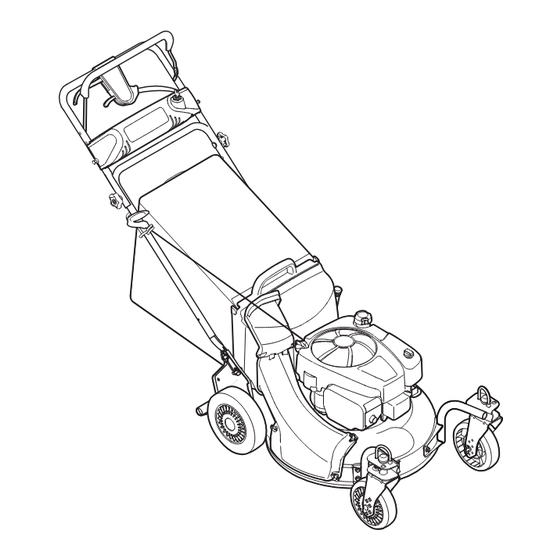
Operator's Manual
21" SELF PROPELLED MOWER
Model No. 247.887761
CAUTION: Before using
this product, read this
manual and follow all
safety rules and operating
instructions.
Sears Brands Management Corporation, Hoffman Estates, IL 60179, U.S.A.
Visit our website: www.craftsman.com
• SAFETY
• ASSEMBLY
• OPERATION
• MAINTENANCE
• PARTS LIST
• ESPAÑOL, p. 39
FORM NO. 769-04706D
6/22/2011
Advertisement
Chapters
Table of Contents

Related Manuals for Craftsman 12AE999P099


Summary of Contents for Craftsman 12AE999P099
- Page 1 CAUTION: Before using • PARTS LIST this product, read this • ESPAÑOL, p. 39 manual and follow all safety rules and operating instructions. Sears Brands Management Corporation, Hoffman Estates, IL 60179, U.S.A. Visit our website: www.craftsman.com FORM NO. 769-04706D 6/22/2011...
-
Page 2: Table Of Contents
FOR TWO YEARS from the date of purchase, this product is warranted against any defects in material or workmanship. Defective product will receive free repair or free replacement if repair is unavailable. For warranty coverage details to obtain repair or replacement, visit the web site: www.craftsman.com. This warranty covers ONLY defects in material and workmanship. Warranty coverage does NOT include: •... - Page 3 SAFETY INSTRUCTIONS WarninG DanGer this machine was built to be operated according to the safe opera- this symbol points out important safety instructions which, if not tion practices in this manual. as with any type of power equipment, followed, could endanger the personal safety and/or property of carelessness or error on the part of the operator can result in serious yourself and others.
- Page 4 SAFETY INSTRUCTIONS • the blade control handle is a safety device. Never attempt to bypass its operation. Doing so makes the safety device inopera- • Mow across the face of slopes; never up and down. exercise tive and may result in personal injury through contact with the extreme caution when changing direction on slopes.
- Page 5 SAFETY INSTRUCTIONS • extinguish all cigarettes, cigars, pipes and other sources • Do not change the engine’s governor setting or over-speed the of ignition. engine. the governor controls the maximum safe operating speed of the engine. • Never fuel machine indoors because flammable vapors will accumulate in the area.
- Page 6 SAFETY INSTRUCTIONS saFeTY sYmbOls this page depicts and describes safety symbols that may appear on this product. Read, understand, and follow all instructions on the machine before attempting to assemble and operate. Symbol Description READ THE OPERATOR’S MANUAL(S) Read, understand, and follow all instructions in the manual(s) before attempting to assemble and operate DANGER —...
-
Page 7: Slope Guide
SLOPE GUIDE... - Page 8 this page left intentionally blank.
-
Page 9: Safety Labels
SAFETY LABELS DO NOT OPERATE UNLESS AN UNDAMAGED DISCHARGE COVER OR ENTIRE GRASS CATCHER IS IN PLACE . AVOID SERIOUS INJURY OR DEATH • KEEP HANDS AND FEET AWAY FROM ROTATING PARTS. • REMOVE OBJECTS THAT CAN BE THROWN BY THE BLADE IN ANY DIRECTION. WEAR SAFETY GLASSES. -
Page 10: Assembly
ASSEMBLY IMPORTANT: this unit is shipped without gasoline or oil in the engine. Be certain to service engine with gasoline and oil as instructed in the Operation section before starting or running your machine. NOTE: Reference to right and left hand side of the Lawn Mower is observed from the operating position. - Page 11 ASSEMBLY the rope guide, which is connected to the support rod, is located on the right side of the lower handle. See Figure 3 below. Hold blade control against upper handle. Pull starter rope out of the engine. Release blade control. Slip starter rope into rope guide.
- Page 12 ASSEMBLY attaching side Discharge Cover Follow steps below to install the side discharge cover: Remove mulching baffle or grass bag adapter from unit by disconnecting wing nuts. attach side discharge cover to unit and secure with the three wing nuts. See Figure 6. aDjUsTmenTs Cutting Height the cutting height adjustment lever is located above the rear left...
-
Page 13: Operation
OPERATION Blade Control Electric Start Ignition Key Drive Control Shift Lever Cutting Height Adjustment Lever Recoil Starter Gas Cap Oil Cap/ Dipstick Side Discharge Cover Figure 9 blaDe COnTrOl eleCTriC sTarT iGniTiOn keY the blade control is attached to the upper handle of the mower. See the electric start ignition key is located on the left side of the handle Figure 9. - Page 14 OPERATION Gas anD Oil Fill-UP IMPORTANT: this unit is shipped without gasoline or oil in the engine. Be certain to service engine with gasoline and oil as instructed in this section before starting or running your machine. (one 18 ounce bottle shipped with unit) First Time Use Remove oil fill dipstick (G).
- Page 15 OPERATION TO sTarT enGine Standing behind the mower, squeeze the blade control handle against upper handle. See Figure 11. this mower has two separate starting systems, electric and recoil. electric start: turn ignition key to the right to start the engine. Release the key after the engine starts.
-
Page 16: Service And Maintenance
SERVICE AND MAINTENANCE mainTenanCe sCHeDUle WarninG Follow the maintenance schedule given below. this chart describes service guidelines only. Use the Service Log column to keep track of Before performing any type of maintenance/service, disengage all completed maintenance tasks. To locate the nearest Sears Service controls and stop the engine. - Page 17 SERVICE AND MAINTENANCE WarninG always stop engine, disconnect spark plug wire, and ground against engine before performing any type of maintenance on your machine. Porcelain electrode General reCOmmenDaTiOns • always observe safety rules when performing any maintenance. • the warranty on this lawn mower does not cover items that have been subjected to operator abuse or negligence.
- Page 18 SERVICE AND MAINTENANCE Check engine Oil Check oil level before each operation. Be sure oil level is maintained. Check the oil with the engine stopped and level. Remove the oil fill dipstick and wipe it clean. Insert and tighten dipstick. Remove it to check the oil level. If the oil level is near or below the lower limit mark on the dipstick, remove the oil filler cap/dipstick, and fill with the recommended oil Oil Fill/ Dipstick...
- Page 19 SERVICE AND MAINTENANCE CleaninG DeCk Clean underside of the mower deck once a season to prevent build-up of grass clippings or other debris. Follow steps below for this job. Disconnect spark plug wire. Drain gasoline from lawn mower or place a piece of plastic under the gas cap. tip mower so that it rests on the housing, keeping the muffler side down.
- Page 20 SERVICE AND MAINTENANCE blaDe Care Periodically inspect the blade adapter for cracks, especially if you strike a foreign object. Replace when necessary. Follow the steps below for blade service. WarninG when removing the cutting blade for sharpening or replacement, protect your hands with a pair of heavy gloves or use a heavy rag to hold the blade.
- Page 21 SERVICE AND MAINTENANCE Open battery cover, remove positive and negative leads from battery, remove and replace with new battery. Connect the positive lead to the positive side of the battery pack, then connect the negative side. NOTE: the battery you have may differ slightly from the one shown in Figure 19.
-
Page 22: Off-Season Storage
OFF-SEASON STORAGE WarninG Never store lawn mower with fuel in tank indoors or in poorly ventilated areas where fuel fumes may reach an open flame, spark, or pilot light as on a furnace, water heater, clothes dryer, or gas appliance. PreParinG THe enGine PreParinG THe laWn mOWer For engines stored over 30 days:... -
Page 23: Troubleshooting
TROUBLESHOOTING WarninG Before performing any type of maintenance/service, disengage all controls and stop the engine. wait until all moving parts have come to a complete stop. Disconnect spark plug wire and ground it against the engine to prevent unintended starting. always wear safety glasses during operation or while performing any adjustments or repairs. -
Page 24: Parts List
PARTS LIST Self Propelled Mower — Model No. 247.887761... - Page 25 PARTS LIST Self Propelled Mower — Model No. 247.887761 Ref. No. Part No. Description Ref. No. Part No. Description 964-04093A Grass Catcher 647-0004A Blade Control 747-0940A-0637 Support Rod w/ Rope Guide 753-0717 Upper Control Housing 747-0939 Pivot Rod 731-0620A Drive Control 747-0937-0637 Grass Catcher Frame 753-0717...
- Page 26 PARTS LIST self Propelled mower — model no. 247.887761...
- Page 27 PARTS LIST self Propelled mower — model no. 247.887761 Ref. No. Part No. Description Ref. No. Part No. Description 682-7528-0637 Chain Cover assembly 914-0474 Cotter Pin 741-0324a Flge Bearing .506 ID x .590 Lg 710-1652 Screw 1/4-14 x .825 682-7526-0637 transmission axle assembly 936-0264 Flat washer.330 ID x.630 OD...
- Page 28 PARTS LIST Craftsman engine model no. 12s905-2732-b1 For Craftsman mower model no. 247.887761 1330 REPAIR MANUAL 48 SHORT BLOCK 1058 OPERATOR’S MANUAL 1329 REPLACEMENT ENGINE 1376 1375 1430 1264 1263...
- Page 29 PARTS LIST Craftsman engine model no. 12s905-2732-b1 For Craftsman mower model no. 247.887761 883A 1034 1029 1022 1023 1026...
- Page 30 PARTS LIST Craftsman engine model no. 12s905-2732-b1 For Craftsman mower model no. 247.887761 957A 1059 216A 1395 137A...
- Page 31 PARTS LIST Craftsman engine model no. 12s905-2732-b1 For Craftsman mower model no. 247.887761 1036 EMISSIONS LABEL 334A...
- Page 32 PARTS LIST Craftsman engine model no. 12s905-2732-b1 For Craftsman mower model no. 247.887761 121 CARBURETOR OVERHAUL KIT 358 ENGINE GASKET SET 883A 1022 1430 1430A 1095 VALVE GASKET SET 883A 1022...
- Page 33 PARTS LIST Craftsman engine model no. 12s905-2732-b1 For Craftsman mower model no. 247.887761 Ref. Ref. Part No. Description Part No. Description Short Block (Not available at this printing) 798947 Cylinder assembly 796596 Gasket-Intake 796961 Kit-Bushing/Seal (Magneto Side) 697316 Rope-Starter 299819S...
- Page 34 PARTS LIST Craftsman engine model no. 12s905-2732-b1 For Craftsman mower model no. 247.887761 Ref. Ref. Part No. Description Part No. Description 690662 695268 adapter-wire 796499 armature-Magneto 795440 Seal-Valve 793454 Screw (Magneto armature) 796492 Base-air Cleaner 334a 796537 Stud (Magneto armature)
- Page 35 NOTES...
- Page 36 (this page applicable in the U.S.a. and Canada only.) sears brands management Corporation (sears), the California air resources board (Carb) and the United states environmental Protection agency (U.s. ePa) emission Control system Warranty statement (Owner’s Defect Warranty rights and Obligations) eMISSION CONtROL waRRaNty COVeRaGe IS aPPLICaBLe tO CeRtI- yeaR 1997 aND LateR eNGINeS wHICH aRe PURCHaSeD aND USeD FIeD eNGINeS PURCHaSeD IN CaLIFORNIa IN 1995 aND tHeReaF-...
- Page 37 look For relevant emissions Durability Period and air index information On Your engine emissions label Engines that are certified to meet the California Air Resources Board (CARB) Tier 2 Emission Standards must display information regarding the Emissions Durability Period and the Air Index. Sears Brands Management Corporation makes this information available to the consumer on our emission labels.
- Page 38 REPAIR PROTECTION AGREEMENT Congratulations on making a smart purchase. Your new Craftsman® product is designed and manufactured for years of dependable operation. But like all products, it may require repair from time to time. That’s when having a Repair Protection Agreement can save you money and aggravation.
-
Page 39: Declaración De Garantía
Los productos defectuosos serán reparados sin costo o reemplazados sin costo si la reparación no está disponible. Para obtener información sobre el alcance de la garantía y solicitar la reparación o el reemplazo, visite el sitio Web: www.craftsman.com. Esta garantía cubre ÚNICAMENTE los defectos en los materiales y en la mano de obra. Esta garantía NO cubre: •... -
Page 40: Instrucciones De Seguridad
INSTRUCCIONES DE SEGURIDAD aDVerTenCia PeliGrO esta máquina fue construida para ser operada de acuerdo con La presencia de este símbolo indica que se trata de instrucciones las reglas de seguridad contenidas en este manual. al igual que importantes de seguridad que se deben respetar para evitar con cualquier tipo de equipo motorizado, un descuido o error por poner en peligro su seguridad personal y/o material y la de otras parte del operador puede producir lesiones graves. - Page 41 INSTRUCCIONES DE SEGURIDAD • Una cubierta de descarga faltante o dañada puede provocar el • Nunca opere la cortadora sin las guardas apropiadas, cubierta de contacto con la cuchilla o lesiones por objetos arrojados. descarga, guarda para recorte, manija de control de la cuchilla y otros dispositivos de seguridad y protección en su lugar y •...
- Page 42 INSTRUCCIONES DE SEGURIDAD niñOs • Nunca saque la tapa del gas ni agregue combustible mientras el motor está caliente o en marcha. Deje que el motor se enfríe por Pueden ocurrir accidentes trágicos si el operador no está atento a la lo menos dos minutos antes de volver a cargar combustible.
- Page 43 INSTRUCCIONES DE SEGURIDAD nO mODiFiqUe el mOTOr • Después de golpear con algún objeto extraño, detenga el motor, desconecte el cable de la bujía y conecte el motor a masa. Para evitar lesiones graves o la muerte, no modifique el motor bajo Inspeccione minuciosamente la máquina para determinar si está...
- Page 44 INSTRUCCIONES DE SEGURIDAD símbOlOs De seGUriDaD esta página representa y describe la seguridad los símbolos que pueden parecer en este producto. Lea, comprenda, y siga todas instrucciones en la máquina antes procurar para reunir y operar. Símbolo Descripción LEA EL MANUAL(S) DEL OPERADOR Lea, comprenda, y siga todas instrucciones en el manual (manuales) antes procurar para reunir y operar.
-
Page 45: Guía De Cuesta
INSTRUCCIONES DE SEGURIDAD... -
Page 46: Montaje
MONTAJE IMPORTANTE: esta unidad se envía sin gasolina ni aceite en el motor. antes de comenzar o correr la máquina cargue el motor con gasolina y aceite como se indica en la sección de operación de este manual NOTA: Las referencias a los lados derecho e izquierdo de la cortadora de césped se hacen observando la máquina desde la posición de operación. - Page 47 MONTAJE La guía de la cuerda, que está conectada a la varilla de sostén, se encuentra sobre el lado derecho de la manija inferior. Vea la Figura 3. Sostenga la manija de control de la cuchilla contra la manija superior. Jale la cuerda de arranque para sacarla del motor.
- Page 48 MONTAJE Conexión de Canal de Descarga lateral Siga los pasos que se indican a continuación para instalar el canal de descarga lateral: extraiga la tolva de abono o el adaptador de la bolsa colectora de la unidad soltando las tuercas de mariposa. acople el canal de descarga lateral y asegure con las tres tuercas mariposa.
-
Page 49: Operación
OPERACIÓN Control de la cuchilla Llave de encendido eléctrico Control de la transmisión Palanca de cambios Palanca de ajuste de la altura de corte arrancador de retroceso tapón de combustible tapón de aceite/varilla de medición del nivel de aceite tolva de descarga lateral Figura 9 COnTrOl De la CUCHilla llaVe De enCenDiDO eléCTriCO... - Page 50 OPeraCiÓn llenaDO De GasOlina Y aCeiTe aceite (se envía una botella junto con la unidad) Primer uso Saque la varilla del nivel de aceite (G). Con la cortadora de césped ubicada en suelo nivelado, vierta el aceite lentamente por dentro del tubo de llenado de aceite del motor hasta la marca de límite alto en la varilla medidora del nivel de Vea la Figura 10.
- Page 51 OPeraCiÓn Para enCenDer el mOTOr Colóquese detrás de la podadora, apriete la manija de control de la cuchilla y sosténgala contra la manija superior. Vea la Figura 11. este cortacésped tiene dos sistemas iniciales separados, eléctricos y retroceso. arrancador eléctrico: Gire la llave de encendido a la derecha para arrancar el motor.
-
Page 52: Servicio Y Mantenimiento
serViCiO Y manTenimienTO PrOGrama De manTenimienTO aDVerTenCia Siga el cronograma de mantenimiento que se presenta a continuación. esta tabla sólo describe pautas de servicio. Utilice la columna Registro antes de realizar cualquier tipo de mantenimiento o servicio, desenganche de Servicio para hacer el seguimiento de las tareas de mantenimiento todos los controles y detenga el motor. - Page 53 serViCiO Y manTenimienTO aDVerTenCia Detenga siempre el motor, desconecte el cable de la bujía y haga masa contra el motor antes de realizar cualquier tarea de mantenimiento a su máquina. Porcelana electrodo reCOmenDaCiOnes Generales • Respete siempre las reglas de seguridad cuando realice tareas de mantenimiento.
- Page 54 serViCiO Y manTenimienTO Comprobar el aceite del motor Comprobar el nivel de aceite antes de cada operación. asegúrese de que el nivel de aceite se mantiene. Revise el aceite con el motor parado y nivelado. Quite la tapa del depósito de aceite/varilla medidora del nivel de Tapón de aceite y límpiela.
- Page 55 serViCiO Y manTenimienTO lUbriCaCiÓn Control de la cuchilla Lubrique con aceite ligero los puntos de pivote del control de la cuchilla al menos una vez cada estación. este controle debe funcionar libremente en ambas direcciones. Vea la Figura 15. ruedas y rueditas Lubrique las ruedas y rueditas una vez por temporada con aceite ligero (o aceite para motor).
- Page 56 serViCiO Y manTenimienTO ajUsTe Del Cable De la PalanCa De CambiOs Puede ser necesario realizar un ajuste periódico del cable de cambios de seis velocidades debido al desgaste normal del cable. el ajuste es necesario si las seis velocidades no funcionan bien. La ménsula ajustable del cable se localiza sobre el lado izquierdo de la cortadora de césped junto al motor.
- Page 57 serViCiO Y manTenimienTO CambiO De la baTería aDVerTenCia Las baterías contienen ácido sulfúrico que puede causar quema- duras. No ponga en corto circuito ni mutile las baterías de ninguna manera. No coloque las baterías sobre fuego dado que pueden explotar o emitir materiales tóxicos. afloje las perillas en estrella que sujetan las manijas inferior y superior y con cuidado doble la manija superior hacia la manija inferior tal como se muestra en la Figura 19.
- Page 58 serViCiO Y manTenimienTO IMPORTANTE: Siempre conecte el conductor del cargador en del paquete de baterías en primer lugar, y luego inserte el enchufe del cargador de baterías en un tomacorriente residencial estándar de 120 voltios. Siga esta secuencia siempre que cargue la batería. aDVerTenCia Utilice únicamente el cargador de baterías suministrado con esta cortadora de césped.
-
Page 59: Almacenamiento Fuera De Temporada
ALMACENAMIENTO FUERA DE TEMPORADA aDVerTenCia Nunca almacene la cortadora de césped con combustible en el tanque en un espacio cerrado o en áreas con poca ventilación, donde los gases del combustible puedan alcanzar el fuego, chispas o una luz piloto como la que tienen algunos hornos, calentadores de agua, secadores de ropa o algún otro dispositivo a gas. -
Page 60: Solución De Problemas
SOLUCIÓN DE PROBLEMAS aDVerTenCia antes de realizar cualquier tipo del mantenimiento/servicio, suelte todos los mandos y pare el motor. espere hasta que todas las partes de movimiento hayan venido a una parada completa. Desconecte el alambre de bujía y báselo contra el motor para prevenir el comienzo involun- tario. - Page 61 (esta página se aplica sólo en ee.UU. y Canadá). sears brands management Corporation, el Consejo de recursos ambientales de California (Carb) y la agencia de Protección ambiental de los estados Unidos (ePa) Declaración de garantía del sistema de control de emisiones (derechos y obligaciones de la garantía de defectos del propi- etario) La COBeRtURa De La GaRaNtÍa De CONtROL De eMISIONeS eS y PaRa LOS MODeLOS CeRtIFICaDOS DeL aÑO 1997 y POSteRIOReS,...
- Page 62 busque el período de duración de emisiones importantes yla información de clasificación de aire en la etiqueta de emisiones de su motor Los motores cuyo cumplimiento con los estándares de emisión Tier 2 de la Comisión de Recursos Ambientales de California (CARB) esté...
- Page 63 ACUERDO DE PROTECCIÓN PARA REPARACIONES Felicitaciones por haber realizado una adquisición inteligente. El producto Craftsman® que ha adquirido está diseñado y fabricado para brindar muchos años de funcionamiento confiable. Pero como todos los productos a veces puede requerir de reparaciones. Es en ese momento cuando el disponer de un Acuerdo de protección para reparaciones le puede ahorrar dinero y problemas.
- Page 64 Get it fixed, at your home or ours! Your Home For troubleshooting, product manuals and expert advice: www.managemylife.com For repair – in your home – of all major brand appliances, lawn and garden equipment, or heating and cooling systems, no matter who made it, no matter who sold it! For the replacement parts, accessories and owner’s manuals that you need to do-it-yourself.
Need help?
Do you have a question about the 12AE999P099 and is the answer not in the manual?
Questions and answers