Table of Contents

Related Manuals for PowerTec UT1008


Summary of Contents for PowerTec UT1008
- Page 1 Model No. UT1008 Owner's Manual Planer Stand Visit us on the web at www.powertecproducts.com You will need this manual for safety instructions, operating procedures, and warranty. Put it and the original sales invoice in a safe, dry place for future reference.
- Page 2 TABLE OF CONTENTS PRODUCT SPECIFICATIONS SECTION PAGE Model No. UT1008 23-1/16" x 20-1/8" Top (covered in Melamine) (585.77 x 511.18 mm) SAFETY RULES Height (with top) 29.5" (749.3 mm) Safety Rules Shelf (steel) PARTS AND CONTENTS Foot Print 26-3/4” x 24-7/8"...
- Page 3 SAFETY RULES FOLLOW ALL STANDARD SHOP SAFETY WARNING PRECAUTIONS, INCLUDING: For your own safety, read all of the rules and precautions before • Keep children and visitors at a safe distance from work area. operating tool. • Keep work area clean. Cluttered work areas invite accidents. WARNING Work area should be properly lit.
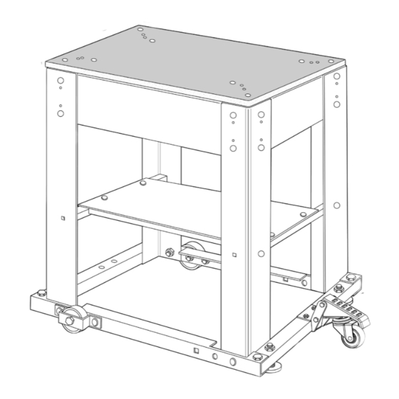
- Page 4 PLANER STAND PARTS AND CONTENTS UNPACKING Refer to Figure 1 • Your new Planer Stand is shipped complete in one carton. Contact the customer service center if any parts are missing. • Examine shipping carton for freight damage before opening. If shipping carton is damaged le a claim with the carrier immediately. •...
- Page 5 ASSEMBLY TOOLS NEEDED See Figure 3. Center Wheel (D) inside Wheel Bracket (E). Align to side-holes on the Long Base Rail (A). Insert 5/16"- • 5/8" and 1/2" open wrench or socket and socket wrench 18 x 2-1/2" Hex Head Half Thread Bolt (O) through center •...
- Page 6 STAND ASSEMBLY LOWER SHELF ASSEMBLY Items Needed Items Needed ITEM DESCRIPTION ITEM DESCRIPTION Legs Shelf Short Upper Flanges Rails 5/16"-18 x 5/8" Carriage Bolts Long Upper Flanges Rails 5/16" Lock Washers Tie Bars 5/16"-18 Nuts 5/16"-18 x 5/8" Carriage Bolts See Figure 7.
- Page 7 PLANER TO STAND WARNING Serious injury could result. Center the planer on the stand. Planer Not Included. Refer to the planer manufacturer’s Failure to center the planer could lead to an unstable assembly. instructions for recommended mounting hardware (sold separately) CAUTION Figure 9 Be careful not to drill into the anges when drilling holes.
- Page 8 30- DAY SATISFACTION GUARANTEE POLICY During the rst 30 days after the date of purchase, if you are dissatis ed with the performance of this POWERTEC tool for any reason, you may return the tool to the retailer from which it was purchased for a full refund or exchange. You must present proof of purchase and return all original equipment packaged with the original product.
Need help?
Do you have a question about the UT1008 and is the answer not in the manual?
Questions and answers