Advertisement
Quick Links
Advertisement

Related Manuals for TOHATSU MFS15C


Summary of Contents for TOHATSU MFS15C
- Page 1 MFS15/20C Disassembling & Reassembling procedure TOHATSU Corporation Japan Service Div.
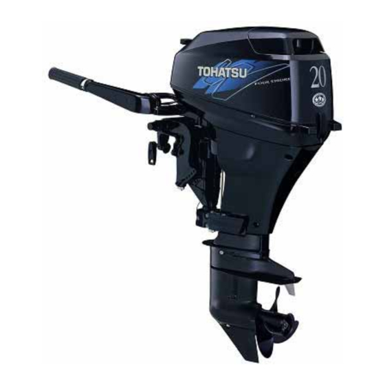
- Page 2 MFS20C Open Packing ~ PDI <Open Packing of carton box ~ PDI> Open the packing Check the carton box for breakage or damage of the packing before opening. Check the contents Open the carton box and check the contents. Main part : Out board motor, with Propeller Enclosed parts : Fuel tank, Fuel hose, Tools, Owner’s manual, Spark plugs (2pcs), Emergency...
- Page 3 Check for external scratches and cracks, according to the PDI sheet. Visual Inspection Throttle Linkage Operation Engine Oil Level Propeller Selection Electric Starter Operation Shift Lever Operation Throttle Handle Operation Indicator Lamp and Buzzer Stop Switch Operation...
- Page 4 Refer to the PDI sheet for each part check points. *Necessity of the PDI Tohatsu outboard motors are produced in a factory and each adjustment is tested by running before shipment. However, dealers and distributors need to adjust for their area.
- Page 5 Customer questions answered by Dealership Personnel Gauge Operation/Warning Symbols Explained Break-in Time Placed on Engine by Dealership Personnel 2-Stroke: Use of Tohatsu 2 stroke/TC-W3 or Equivalent Rated Oil hours: Minutes: 4-Stroke: Use of Tohatsu 4 stroke or Equivalent Rated Oil...
- Page 6 □MFS20C Maintenance section Power head <Disassembly> Remove each terminal of harness to remove the power head , ○ *Battery cable (○ *Remote control harness coupler and connectors (Remote control model) *Warning lamp, starter switch and stop switch *PTT switch coupler, each ground wire (PTT model) ...
- Page 7 *Fuel hose connection (fuel filter’s inlet side) *Cooling water hose connection After removing each connection, remove the apron and power head mounting bolts. (It is possible to detach it smoothly by removing the water pipe lock plate) Remove the power head.
- Page 8 (Oil strainer and Plunger are detached up and down and inversely.) Remove the recoil starter.
- Page 9 ·Loose the flywheel nut using the special tool (Flywheel Puller kit 3B7-72211-0). ·Remove the flywheel from crankshaft using a flywheel Puller. Remove the all electric system and sensor connections, and remove the main harness.
- Page 10 Remove the bolts, and remove the fuel pump. Remove the bolts, and remove the intake manifold with carburetor.
- Page 11 Remove the bolts, and remove the starter motor. Loose the drive pulley nut ○ using crank holder (○ ○ b To prevent the piston and the valve being interfered Crank holder Remove the timing belt, drive pulley, and cam pulley.
- Page 12 Remove the bolts, and remove the cylinder head cover. Remove the bolts, and remove the cylinder head. Remove the bolts, and Remove the oil pump assembly.
- Page 13 Loose the rocker arm lock nut, and loosen adjusting screw as much as possible. Remove the rocker arm, spring, washer and rocker arm shaft. Remove the cam shaft. Compress the valve spring by using compressor. Then, remove cotter, spring and valve.
- Page 14 Remove the oil seal and install new oil seal. Inspect in of valve spring and valve. (1) Valve spring free length (2) Valve spring inclination limit length: 35.0mm ~ 33.5mm Inclination limit: 1.5mm (3) Valve stem Outside diameter (4) Valve stem deflection limit Intake side: 5.46mm ~ 5.48mm Intake side: 0.05mm...
- Page 15 <Inspect in of rocker arm and rocker arm shaft> <Inspect in of cam shaft> Measure rocker arm inner diameter and Rocker Measure deflection camshaft. shaft Outer diameter. deflection limit: 0.05mm (1)Rocker arm Inner diameter: 13.01mm~13.05mm (2)Rocker shaft Outer diameter: 12.94mm~12.99mm (3)Shaft clearance 0.006mm~0.060mm Cylinder Head...
- Page 16 (1)Installation of valves Attach the new valve stem seal. Attach the parts to the valve in order of the retainer in the valve, valve spring seat, and the valve spring Apply Oil to valve guide. Stem seal Intake: Black Exhaust: Green Attach the cotter with compressing the valve spring.
- Page 17 (3) Attaching of locker arm shaft Apply enough oil to the camshaft and rocker arm shaft. (4) Attaching of oil pump Align cuts of oil pump drive shaft and camshaft pin with each other to install oil pump. Refuel engine oil to the oil passage in 2ml. (Apply engine oil to oil pump o-ring and camshaft lower side journal.) Camshaft’s pin (5) Attaching of cylinder head...
- Page 18 Be sure to align mark of the belt guide ○ and mark of the cylinder block ○ Certainly ·Use a new cylinder head gasket. ·Do not turn cam shaft pulley with the timing belt removed. (Doing so can make pistons and valves interfere with each other, resulting in damages to these parts) Disassembly of Cylinder Block Remove installation bolts, and remove crank case.
- Page 19 Remove installation bolts, and connecting rod cap. Remove crank shaft from cylinder block. Check the balance of crank shaft. Crank shaft Deflection Limit: 0.05mm (The crank shafts are exchanged when the amplitude is more than the limit value.)
- Page 20 Remove connecting rods with piston assemblies from cylinder block. (Be careful not to damage the piston and piston ring.) Remove the piston pin clip then the piston from the connecting rod. Inspection of power head cooling water passage Remove the thermostat cap and thermostat. Check whether thermostat valve is open by catching debris.
- Page 21 Measurement of valve open temperature and lift. Measure the temperature of valve opening. Measure the valve open lift when water temperature is 75°C Temperature of open valve:60°C±1.5°C Water temperature : 75°C Valve open lift : 3.0mm Remove the anode cap and anode. The anode has decreased is confirmed Check corrosion and remove clogs and debris from cooling water passage.
- Page 22 (1)Install the crank shaft. Assembly the piston and connecting rod (The clip suits connecting rod to the UP mark of the piston by using the new article.) Put connecting rods and piston assemblies into cylinder with piston crown UP mark directing fly wheel side and piston slider set on the pistons.
- Page 23 <Inspection oil clearance> Put a plasti-gauge on the crankpin, and tighten the connecting rod bolts with the specified torque. Tightening torque:1st step 0.6kg-m 2nd step 1.2kg-m Remove the piston cap, and measure width of crushed plasti-gauge on each crank pin. Oil clearance:0.015mm~0.060mm ...
- Page 24 (2) Apply sealant to crank case. Degrease crank case and cylinder mating faces. Apply (LOC TITE 518) to crank case’s mating surface. (3) Install the crank case. Tighten crank case bolts in the following picture’s steps. Tightening Torque 1st step 0.6kg-m 1.2kg-m 2nd step...
- Page 25 Power Head <Assembly> Assembling power head reverse of their disassemble steps. Tightening torque as follows: Size x Q'ty Power unit installation M8x6 1.0kg.m 3.0kg.m Flywheel magneto 8.0kg.m *Note (1) Confirmation of oil strainer hose position When attaching the power head, put the oil strainer hose into the oil pan surely. (2) When attaching the power head, be sure not to pinch wirings and hoses.
- Page 26 Bracket <Disassembly> Tilt up the outboard motor. Remove the spring pin of shaft rod joint using a spring pin tool (345-72227-0). Remove the lower unit mounting bolts, and pull lower unit assembly. Remove the shift lever shaft, disconnect the shift rod.
- Page 27 Remove the bolts, and remove the bottom cowl from the drive shaft housing. Remove the bolts, remove the idol port cover. Remove the ground wire bolt. Remove the lower mount bolts.
- Page 28 Remove the upper mount nuts. Remove the drive shaft housing.
- Page 29 Bracket <Assembly> Assembling bracket reverse of their disassemble steps. Tightening torque as follows: Size x Q'ty Gear case nut M8x4 2.4kg.m Mounting rubber (upper) bolt M8x4 1.3kg.m Mounting rubber (lower) nut M8x3 1.3kg.m Mounting rubber (upper) nut M8x2 2.7kg.m Engine basement bolt M8x6 3.0kg.m *Note...
- Page 30 Lower Unit <Disassembly> Drain the gear oil. Tilt up the outboard motor. Remove the spring pin of shaft rod joint using spring pin tool (345-72227-0). (Lower unit can be separated without removing of the gearshift shaft.) Remove the propeller. Remove the lower unit mounting bolts, and remove the lower unit assembly from the drive shaft housing.
- Page 31 Remove the propeller shaft housing together with the propeller shaft. When pulling out propeller shaft housing, remove clutch push rod together with the housing assembly as shown. Remove the water pump housing, impeller and impeller key. ...
- Page 32 Remove the pump housing (lower). Don’t lose shim under the pump case (lower). Fix gear case on a vise with its propeller opening upper makes for easy work. Remove the bevel gear nut using special tools (Bevel gear nut wrench (346-72231-0) and socket (350-72232-0)).
- Page 33 Pull the drive shaft, and remove the bevel gear B. Each part should be cleaned. Otherwise the backlash can not have correct measurement if gear oil remains surface of gears. *About necessity of the backlash measurement management The recent outboard motor tends it to be upsized. The gear in the lower unit transmits the big output to a propeller only by the primary gear reduction of bevel gear.
- Page 34 [The Backlash] There are kind of gear B in the case. These have the processing dimensions gaps of a gear case and need an adjustment using shims for gear. This adjustment is needed to have a best gear tooth. It is done to backlash adjustment in a factory, and it is shipped to the world. The way of thinking is as follows.
- Page 35 2. Assemble the special tool (3C8-72234-0) to the lower case and turn the propeller shaft tightening the bolts of a clock wise as picture. When the A gear bearing turn together, turn the nut additionally 45degrees. This is to fix the A gear for backlash measurement. 3.
- Page 36 *When you measure the backlash, better to settle lower side as shown. The reason is for stable bearing contact. In addition, when you measure the backlash, hold the drive shaft by your hand closely to the lower case. The reason is the drive shaft shakes caused by hand and a correct measurement is not possible.
- Page 37 2. Apply pre-load to the A gear like backlash measurement. (Turn the propeller shaft tightening bolt clockwise. When the A gear begins to turn together, turn the nut additionally 45 degrees.) 3. Turn the drive shaft 6 times by pulling the drive shaft to the top side. 4.
- Page 38 Lower Unit <Assembly> Assembling lower unit reverse of their disassemble steps. Tightening torque as follows: Size x Q'ty Gear case mounting nut M8x4 2.4kg.m Bevel gear B nut 3.5kg.m *Note (1) Don’t reuse removed shift rod spring pin, replace with new one. (2) After attach impeller to drive shaft, install the water pump, turn the drive shaft clockwise and set the upper water pump case to the impeller.
- Page 39 1) Removal of needle roller bearing New Bearing Needle bearing attachment Driver rod (1) Put a needle bearing attachment in a driver rod and insert it in the propeller shaft housing from arrow direction as picture. (2) Remove needle roller bearing using special tool. 2) Installation of needle roller bearing Driver rod Needle bearing・attachment...
- Page 40 bearing.) (2) Push new needle roller bearing in to the propeller shaft housing by using press. Confirm that a needle roller bearing was completely press-fitted Removal and installation of needle roller bearing in gear case 1) Removal of needle roller bearing Bolt Plate Guide...
- Page 41 2) Installation of the needle roller bearing Plate Guide Attachment New Bearing (1) Attach the bearing attachment and bearing guide to the needle roller bearing rod. (2) Fix the bolts, collars and Plate to the Guide. And attach this assembly to the gear case from the direction of the arrow A.
- Page 42 Open a gap between the bearing and A gear using a universal puller plate. Put two screw drivers into the gap, and remove C gear by scooping out as picture. 2) Install the A gear and bearing (1) Combine center plate and a bearing attachment for a with driver rod, and insert a ball bearing in a gear case.(Be sure to apply oil to bearing outer and press bearing outer.) (2) Insert A gear into the bearing using the backlash measuring tool kit (3C8-72234-0).
- Page 43 Assemble all of parts about lower unit. If all reassemble work is finished, check air leak from lower unit by leakage tester. (Measure pressure: 0.5 kg/cm2) Standard bolt and nut torque as follows 0.4kg.m 0.6kg.m 1.3kg.m 2.7kg.m Adjustment <Adjustment before firing> Engine Throttle linkage connection PS pre-setting...
-
Page 44: Maintenance Data
Maintenance Data... - Page 45 Auto-by starter...
-
Page 47: Specification
SPECIFICATION... - Page 49 70°...
- Page 50 ...
- Page 51 MFS15/20C Disassembling & Reassembling procedure 2008 by TOHATSU Corporation, Japan. Edition, Oct. 2008 All rights reserved. Any reprinting or unauthorized use is expressly prohibited without the written permission of TOHATSU Corporation, Japan.
Need help?
Do you have a question about the MFS15C and is the answer not in the manual?
Questions and answers