Table of Contents
Advertisement
Quick Links
Advertisement
Table of Contents

Related Manuals for Corsair ST2000DM008


Summary of Contents for Corsair ST2000DM008
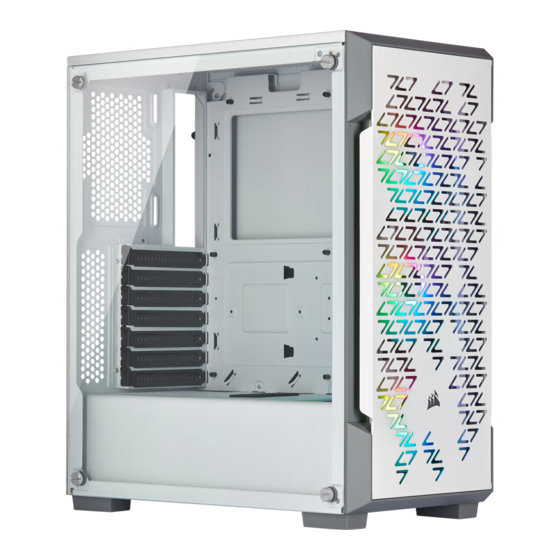
- Page 1 User Manual of Product 1: Corsair iCUE 220T RGB Airflow Tempered Glass Mid-Tower Smart Case, White User Manual of Product 2: Seagate BarraCuda 2TB Internal Hard Drive HDD – 3.5 Inch SATA 6Gb/s 7200 RPM 256MB Cache – Frustration Free...
- Page 2 220T RGB YOUTUBE: youtube.com/corsairhowto © 2019 CORSAIR MEMORY, Inc. All rights reserved. CORSAIR and the sails logo are registered trademarks in the United States and/or other countries. All other trademarks are the property of their respective owners. Product may vary slightly from those pictured.
- Page 3 ENGLISH ............1 FRANÇAIS ..........11 DEUTSCH ...........21 NEDERLANDS ...........31 ITALIANO ............41 ESPAÑOL ...........51 PORTUGUÊS..........61 POLSKI ............71 PУССКИЙ .............81 العربية ............91...
- Page 4 ENGLISH CASE SPECIFICATIONS ACCESSORY KIT CONTENTS Length ................................395mm Width ................................210mm Height ................................450mm Maximum GPU length ........................... 300mm Maximum CPU height ............................160mm Maximum PSU length ............................180mm Fan locations: Front ............................ 3 x 120mm / 2 x 140mm Fan screws (short) MBD / HDD screws ODD / SSD screws Top ............................
- Page 5 ENGLISH CASE FEATURES REMOVING THE SIDE PANELS INSTALLING THE MOTHERBOARD MATX A — TEMPERED GLASS SIDE PANEL E — SOLID SIDE PANEL B — DUST FILTERS F — FRONT BEZEL C — SSD TRAYS G — 3 x 120mm RGB FANS D —...
- Page 6 ENGLISH INSTALLING HDDs INSTALLING PSU INSTALLING SSDs INSTALLING PCI-e CARDS...
- Page 7 ENGLISH INSTALLING THE FRONT I/O CONNECTORS REMOVING THE FRONT BEZEL USB 3.0 POWER SW POWER LED + HD AUDIO RESET SW POWER LED – MOVING HDD CAGE...
- Page 8 No, only the LED headers. 2. Who should I contact if I received my case damaged or one of the fans is no longer working? Please go to support.corsair.com and request an RMA so that we can replace the damaged part(s).
- Page 9 FRANÇAIS SPÉCIFICATIONS DU BOÎTIER CONTENU DU KIT D’ACCESSOIRES Longueur ................................ 395mm Largeur ................................210mm Hauteur ................................450mm Longueur maximale de carte graphique ...................... 300mm Hauteur maximale du processeur .........................160mm Longueur maximale du bloc d’alimentation ....................180mm Emplacements des ventilateurs: Avant ........................... 3 x 120mm / 2 x 140mm Vis courtes pour ventilateur Vis pour carte Vis pour lecteur optique /...
- Page 10 FRANÇAIS CARACTÉRISTIQUES DU BOÎTIER RETRAIT DES PANNEAUX LATÉRAUX INSTALLATION DE LA CARTE MÈRE MATX A — PANNEAU LATÉRAL EN VERRE TREMPÉ E — PANNEAU LATÉRAL PLEIN B — FILTRE ANTI-POUSSIÈRE F — PANNEAU AVANT C — PLATEAUX DE DISQUE SSD G —...
- Page 11 FRANÇAIS INSTALLATION DES DISQUES DURS INSTALLATION DU BLOC D’ALIMENTATION INSTALLATION DE SSD INSTALLATION DES CARTES PCI-e...
- Page 12 FRANÇAIS RETRAIT DU PANNEAU AVANT INSTALLATION DES CONNECTEURS E/S AVANT USB 3.0 POWER SW POWER LED + HD AUDIO RESET SW POWER LED – BAIE DE DISQUE DUR AMOVIBLE...
- Page 13 2. À qui dois-je m’adresser si mon boîtier est endommagé à l’arrivée ou lorsqu’un ventilateur ne fonctionne plus? Veuillez vous rendre sur le site support.corsair.com et demandez une RMA (autorisation de retour de marchandise) pour que nous puissions remplacer la ou les pièces endommagées.
- Page 14 DEUTSCH TECHNISCHE DATEN DES GEHÄUSES INHALT DES ZUBEHÖRKITS Länge ................................395mm Breite ................................210mm Höhe ................................450mm Maximale GPU-Länge ........................... 300mm Maximale CPU-Höhe .............................160mm Maximale Netzteil-Länge ..........................180mm Lüfterpositionen: Kurze Schrauben für Lüfter Schrauben für die Hauptplatine Schrauben für optische und Vorderseite.......................... 3 x 120mm / 2 x 140mm und Festplattenlaufwerke SSD-Laufwerke Oben ...........................
- Page 15 DEUTSCH FUNKTIONSMERKMALE DES GEHÄUSES ABNEHMEN DER SEITENPLATTEN INSTALLATION DES MOTHERBOARDS MATX A — SEITENABDECKUNG AUS E — MASSIVE SEITENABDECKUNG GEHÄRTETEM GLAS F — BLENDE VORDERSEITE B — STAUBFILTER G — 3 × RGB-LÜFTER, 120 mm C — SSD-SCHÄCHTE H — LIGHTING NODE CORE D —...
- Page 16 DEUTSCH INSTALLATION VON HDD-LAUFWERKEN INSTALLATION DES NETZTEILS (PSU) INSTALLIEREN VON PCI-e-KARTEN INSTALLATION VON SSD-LAUFWERK...
- Page 17 DEUTSCH ABNEHMEN DER VORDEREN BLENDE INSTALLATION DER VORDEREN I/O -ANSCHLÜSSE USB 3.0 POWER SW POWER LED + HD AUDIO RESET SW POWER LED – ABNEHMBARER FESTPLATTENKÄFIG...
- Page 18 2. An wen kann ich mich wenden, wenn ich ein beschädigtes Gehäuse erhalten habe oder einer der Lüfter nicht mehr funktioniert? Gehen Sie zu support.corsair.com und fordern Sie eine RMA an, damit wir die beschädigten Teile ersetzen können. 3. Wo kann ich einen Lüfter anbringen? Lüfter-Einbaupunkte...
- Page 19 NEDERLANDS SPECIFICATIES BEHUIZING INHOUD ACCESSOIRESKIT Lengte ................................395mm Breedte ................................210mm Hoogte ................................450mm Maximale GPU-lengte ........................... 300mm Maximale CPU-hoogte ...........................160mm Maximale PSU-lengte ............................180mm Fanlocaties: Voorzijde ..........................3 x 120mm / 2 x 140mm Schroeven voor fans (kort) Schroeven voor MBD / HDD Schroeven voor ODD / SSD Bovenzijde ..........................
- Page 20 NEDERLANDS ONDERDELEN VAN DE BEHUIZING DE ZIJPANELEN VERWIJDEREN HET MOEDERBORD INSTALLEREN MATX A — ZIJPANEEL VAN GEHARD GLAS E — MASSIEF ZIJPANEEL B — STOFFILTERS F — VOORPANEEL C — SSD-LADES G — 3 x 120mm RGB-FANS D — HDD-LADES H —...
- Page 21 NEDERLANDS HDD’s INSTALLEREN PSU INSTALLEREN SSD’s INSTALLEREN PCI-e-KAARTEN INSTALLEREN...
- Page 22 NEDERLANDS HET VOORPANEEL VERWIJDEREN DE I/O-CONNECTOREN AAN DE VOORZIJDE INSTALLEREN USB 3.0 POWER SW POWER LED + HD AUDIO RESET SW POWER LED – HDD-BEHUIZING VERPLAATSEN...
- Page 23 2. Met wie moet ik contact opnemen als de behuizing beschadigd is of als een van de fans niet meer werkt? Ga naar support.corsair.com en vraag een RMA aan zodat we de beschadigde onderdelen kunnen vervangen. 3. Waar kan ik een fan installeren?
- Page 24 ITALIANO SPECIFICHE CASE CONTENUTO KIT DI ACCESSORI Lunghezza ..............................395mm Larghezza ...............................210mm Altezza ................................450mm Lunghezza massima GPU ..........................300mm Altezza massima CPU ............................160mm Lunghezza massima alimentatore .........................180mm Posizioni delle ventole: Anteriore ..........................3 x 120mm / 2 x 140mm Viti ventola (corte) Viti per scheda madre / Viti per unità...
- Page 25 ITALIANO CARATTERISTICHE CASE RIMOZIONE DEI PANNELLI LATERALI INSTALLAZIONE DELLA SCHEDA MADRE MATX A — PANNELLO LATERALE IN VETRO TEMPRATO E — PANNELLO LATERALE SENZA FINESTRA B — FILTRI ANTIPOLVERE F — LUNETTA ANTERIORE C — VASSOI PER UNITÀ SSD G — 3 VENTOLE RGB DA 120 mm D —...
- Page 26 ITALIANO INSTALLAZIONE DELLE UNITÀ HDD INSTALLAZIONE DELL’ALIMENTATORE INSTALLAZIONE DELLE UNITÀ SSD INSTALLAZIONE DELLE SCHEDE PCI-e...
- Page 27 ITALIANO RIMOZIONE DELLA LUNETTA ANTERIORE INSTALLAZIONE DEI CONNETTORI I/O FRONTALI USB 3.0 POWER SW POWER LED + HD AUDIO RESET SW POWER LED – SCOMPARTO DISCO RIGIDO RIMOVIBILE...
- Page 28 Posizioni di montaggio delle ventole Anteriore 3 x 120mm / 2 x 140mm Superiore 2 x 120mm / 2 x 140mm Posteriore 1 x 120mm Per saperne di più su questo case, visita la pagina del prodotto sul sito corsair.com.
- Page 29 ESPAÑOL ESPECIFICACIONES DEL CHASIS CONTENIDO DEL KIT DE ACCESORIOS Longitud ................................. 395mm Anchura ................................210mm Altura ................................450mm Longitud máxima de GPU ..........................300mm Longitud máxima de CPU ..........................160mm Longitud máxima de la PSU ..........................180mm Ubicación del ventilador: Delantero ..........................3 x 120mm / 2 x 140mm Tornillos para ventilador (cortos) Tornillos para MBD / HDD Tornillos para ODD / SSD...
- Page 30 ESPAÑOL CARACTERÍSTICAS DEL CHASIS RETIRADA DE LOS PANELES LATERALES INSTALACIÓN DE LA PLACA BASE MATX A — PANEL LATERAL DE CRISTAL TEMPLADO E — PANEL LATERAL SÓLIDO B — FILTRO ANTIPOLVO F — EMBELLECEDOR FRONTAL C — BANDEJAS PARA SSD G —...
- Page 31 ESPAÑOL INSTALACIÓN DE LAS UNIDADES HDD INSTALACIÓN DE LA PSU INSTALACIÓN DE LAS TARJETAS PCI-e INSTALACIÓN DE LA UNIDADES SSD...
- Page 32 ESPAÑOL RETIRADA DEL EMBELLECEDOR FRONTAL INSTALACIÓN DE LOS CONECTORES DE E/S FRONTALES USB 3.0 POWER SW POWER LED + HD AUDIO RESET SW POWER LED – CARCASA EXTRAÍBLE PARA HDD...
- Page 33 Puntos de montaje del ventilador Parte delantera 3 x 120mm / 2 x 140mm Parte superior 2 x 120mm / 2 x 140mm Parte posterior 1 x 120mm Para obtener más información sobre este chasis, visite la página del producto en corsair.com.
- Page 34 PORTUGUÊS ESPECIFICAÇÕES DO GABINETE CONTEÚDO DO KIT DE ACESSÓRIOS Comprimento ..............................395mm Largura ................................210mm Altura ................................450mm Comprimento máximo da GPU........................300mm Altura máxima da CPU ...........................160mm Comprimento máximo da PSU ........................180mm Locais das ventoinhas: Frente ..........................3 x 120mm / 2 x 140mm Parafusos para ventoinha Parafusos para MBD / HDD Parafusos para ODD / SSD...
- Page 35 PORTUGUÊS RECURSOS DO GABINETE REMOVER OS PAINÉIS LATERAIS INSTALAR A PLACA-MÃE MATX A — PAINEL LATERAL EM VIDRO TEMPERADO E — PAINEL LATERAL SÓLIDO B — FILTRO DE POEIRA F — BISEL DIANTEIRO C — BANDEJAS PARA SSD G — 3 x VENTOINHA RGB DE 120 mm D —...
- Page 36 PORTUGUÊS INSTALAR HDDs INSTALAR A PSU INSTALAR SSDs INSTALAR PLACAS PCI-e...
- Page 37 PORTUGUÊS REMOVER O BISEL DIANTEIRO INSTALAR OS CONECTORES DE E/S DIANTEIROS USB 3.0 POWER SW POWER LED + HD AUDIO RESET SW POWER LED – COMPARTIMENTO PARA HDD MÓVEL...
- Page 38 3. Onde posso montar uma ventoinha? Montar um fã Frente 3 x 120mm / 2 x 140mm Topo 2 x 120mm / 2 x 140mm Traseira 1 x 120mm Para saber mais sobre este gabinete, visite a página do produto em corsair.com...
- Page 39 POLSKI DANE TECHNICZNE OBUDOWY ZAWARTOŚĆ ZESTAWU AKCESORIÓW Długość ................................395mm Szerokość ...............................210mm Wysokość ..............................450mm Maksymalna długość karty graficznej ......................300mm Maksymalna wysokość procesora ........................160mm Maksymalna długość zasilacza ........................180mm Miejsca montażu wentylatorów: Przód ........................... 3 x 120mm / 2 x 140mm Śruby do wentylatora (krótkie) Śruby do płyty głównej / Śruby do napędu...
- Page 40 POLSKI CECHY OBUDOWY ZDEJMOWANIE PANELI BOCZNYCH MONTOWANIE PŁYTY GŁÓWNEJ MATX A — PANEL BOCZNY Z HARTOWANEGO SZKŁA E — PEŁNY PANEL BOCZNY B — FILTRY PRZECIWKURZOWE F — PANEL PRZEDNI C — TACE NA DYSKI SSD G — 3 WENTYLATORY RGB 120mm D —...
- Page 41 POLSKI MONTOWANIE DYSKÓW TWARDYCH MONTOWANIE ZASILACZA MONTOWANIE DYSKÓW SSD MONTOWANIE KART PCI-e...
- Page 42 POLSKI ZDEJMOWANIE PANELU PRZEDNIEGO MONTOWANIE PRZEDNICH ZŁĄCZY WEJŚCIA / WYJŚCIA USB 3.0 POWER SW POWER LED + HD AUDIO RESET SW POWER LED – RUCHOMA KLATKA NA DYSK TWARDY...
- Page 43 3. Gdzie można zamontować wentylator? Miejsca montażu wentylatorów Przód 3 x 120mm / 2 x 140mm Góra 2 x 120mm / 2 x 140mm Tył 1 x 120mm Więcej informacji na temat obudowy znajduje się na stronie produktu w witrynie corsair.com.
- Page 44 PУССКИЙ ТЕХНИЧЕСКИЕ ХАРАКТЕРИСТИКИ КОРПУСА СОДЕРЖИМОЕ КОМПЛЕКТА АКСЕССУАРОВ Длина ................................395mm Ширина................................210mm Высота ................................450mm Максимальная длина графического процессора ..................300mm Максимальная высота ЦП ..........................160mm Максимальная длина блока питания ......................180mm Расположение вентиляторов: Спереди ..........................3 x 120mm / 2 x 140mm Винта...
- Page 45 PУССКИЙ ОСОБЕННОСТИ КОРПУСА СНЯТИЕ БОКОВЫХ ПАНЕЛЕЙ УСТАНОВКА МАТЕРИНСКОЙ ПЛАТЫ MATX A — БОКОВАЯ ПАНЕЛЬ ИЗ ЗАКАЛЕННОГО СТЕКЛА E — СПЛОШНАЯ БОКОВАЯ ПАНЕЛЬ B — ПЫЛЕВОЙ ФИЛЬТР F — ПЕРЕДНИЙ ОБОДОК C — ЛОТКИ ДЛЯ ТВЕРДОТЕЛЬНЫХ НАКОПИТЕЛЕЙ G — 3 x ВЕНТИЛЯТОР 120mm С ПОДСВЕТКОЙ RGB D —...
- Page 46 PУССКИЙ УСТАНОВКА ЖЕСТКИХ ДИСКОВ УСТАНОВКА БЛОКА ПИТАНИЯ УСТАНОВКА ПЛАТ PCI-e УСТАНОВКА ТВЕРДОТЕЛЬНЫЙ НАКОПИТЕЛЬ...
- Page 47 PУССКИЙ СНЯТИЕ ПЕРЕДНЕГО ОБОДКА УСТАНОВКА ПЕРЕДНИХ РАЗЪЕМОВ ВВОДА-ВЫВОДА USB 3.0 POWER SW POWER LED + HD AUDIO RESET SW POWER LED – ПЕРЕМЕЩАЕМЫЙ ОТСЕК ДЛЯ ЖЕСТКИХ ДИСКОВ...
- Page 48 Нет, она важна только для светодиодных разъемов. 2. К кому следует обратиться, если корпус получен поврежденным или один из вентиляторов не работает? Перейдите на веб-сайт support.corsair.com и запросите разрешение на возврат материалов (RMA), чтобы мы смогли заменить поврежденные детали. 3. Где можно установить вентилятор? Места...
- Page 49 العربية مواصفات العلبة محتويات مجموعة امللحقات الطول 395mm ................................العرض 210mm ................................االرتفاع 450mm ................................الحد األقىص لطول وحدة معالجة الرسومات 300mm ......................الحد األقىص لطول وحدة املعالجة املركزية 160mm ......................الحد األقىص لطول وحدة اإلمداد بالطاقة 180mm ......................... :أماكن املروحة )ب...
- Page 50 العربية مميزات العلبة إزالة اللوحات الجانبية تركيب اللوحة الرئيسية MATX لوحة جانبية صلبة لوحة جانبية من الزجاج املقىس — E — A إطار أمامي مرشحات الغبار — F — B مم مقاس م ر اوح علب محركات األق ر اص ذات الحالة الصلبة 3 —...
- Page 51 العربية تركيب محركات األق ر اص الثابتة تركيب وحدة اإلمداد بالطاقة تركيب محركات األق ر اص ذات الحالة الصلبة تركيب بطاقات منفذ امللحقات اإلضافية الرسيع...
- Page 52 العربية إزالة اإلطار األمامي تركيب موصالت اإلدخال / اإلخ ر اج األمامية USB 3.0 POWER SW POWER LED + HD AUDIO RESET SW POWER LED – علبة محركات األق ر اص الثابتة القابلة للنقل...
- Page 53 م َن الجهة التي يجب أن أتواصل معها يف حال استالم علبة تالفة أو عند تعطل إحدى املراوح ؟ .وطلب ترخيص املواد املسرتجعة حتى نتمكن من استبدال الجزء (األجزاء) التالف ي ُ رجى زيارة موقع support.corsair.com أين ميكنني تركيب مروحة؟ أماكن تركيب املروحة الجزء األمامي...
- Page 54 NOTE ON ENVIRONMENTAL PROTECTION CORSAIR MEMORY, Inc. declara que este equipo cumple ai punti di raccolta pubblici preposti per questo scopo o nei After the implementation of the European Directive This equipment has been tested and found to con la directiva 2011/65/EU.
- Page 55 wet van het betreffende land. Dit symbool op het product, jiným způsobem zpracování výrazně přispíváte k ochraně vedrørende dette fastlægges af de respektive landes nationale καταστήματα αγοράς. Οι λεπτομέρειες ρυθμίζονται στη σχετική de gebruiksaanwijzing of de verpakking duidt erop dat našeho životního prostředí! lovgivning.
- Page 56 SATA Product Manual Standard models ST2000DM008 100817550, Rev. F August 2018...
- Page 57 Revision History Version and Date Description of Changes Rev A, 04/03/2017 Initial release. Rev B, 06/22/2017 7 & 10: Updated Max Height to 20.20mm/0.795 in. 20: Updated Max Height in Figure 2: Mounting dimensions (1 and 2-disk models) Rev C, 10/18/2017 12: Added Figure 1: Location of the HDA temperature check point 15-18: Updated Safety, EMC, FCC &...
-
Page 58: Table Of Contents
www.seagate.com Contents Introduction ................6 About the SATA interface . - Page 59 www.seagate.com Contents Configuring and Mounting the Drive ............19 Handling and static-discharge precautions .
- Page 60 www.seagate.com Figures Figure 1 Location of the HDA temperature check point ..........12 Figure 2 Attaching SATA cabling .
- Page 61 Seagate® Technology Support Services For information regarding online support and services, visit: http://www.seagate.com/contacts/ For information regarding Warranty Support, visit: http://www.seagate.com/support/warranty-and-replacements/ For information regarding data recovery services, visit: http://www.seagate.com/services-software/data-recovery-services/ For Seagate OEM, Distribution partner and reseller portals, visit: http://www.seagate.com/partners/ Seagate BarraCuda Product Manual, Rev. F...
-
Page 62: Introduction
1.0 Introduction This manual describes the functional, mechanical and interface specifications for the following Seagate® BarraCuda® model drives: ST2000DM008 These drives provide the following key features: • Compliant with RoHS requirements in China and Europe. • High instantaneous (burst) data-transfer rates (up to 600MB per second). -
Page 63: Drive Specifications
Unless otherwise noted, all specifications are measured under ambient conditions, at 25°C, and nominal power. For convenience, the phrases the drive and this drive are used throughout this manual to indicate the following drive models: ST2000DM008 Specification summary tables The specifications listed in are for quick reference. - Page 64 Table 1 Drive specifications summary for 2TB model (continued) Drive Specification* ST2000DM008 30°C max (operating) Wet bulb temperature (max) 40°C max (non-operating) –304m to 3048m Altitude, operating (–1000 ft to 10,000 ft) Altitude, non-operating –304m to12,192m (below mean sea level, max) (–1000 ft to 40,000+ ft)
-
Page 65: Formatted Capacity
www.seagate.com Formatted capacity Model Formatted capacity* Guaranteed sectors Bytes per sector 2000GB 3,907,029,168 4096 *One GB equals one billion bytes and 1TB equals one trillion bytes when referring to hard drive capacity. Accessible capacity may vary depending on operating environment and formatting. 2.2.1 LBA mode When addressing these drives in LBA mode, all blocks (sectors) are consecutively numbered from 0 to n–1, where n is the number of guaranteed sectors as defined above. -
Page 66: Start/Stop Times
Start/stop times The start/stop times are listed below. Standard models ST2000DM008 Power-on to ready 11 (typical) (in seconds) Standby to ready 11 (typical) (in seconds) Ready to spindle stop 11 (typical) (in seconds) Time-to-ready may be longer than normal if the drive power is removed without going through normal OS powerdown procedures. -
Page 67: Voltage Tolerance
www.seagate.com 2.7.3 Voltage tolerance Voltage tolerance (including noise): • 5V ±5% • 12V ±10% 2.7.4 Power-management modes The drive provides programmable power management to provide greater energy efficiency. In most systems, users can control power management through the system setup program. The drive features the following power-management modes: Power modes Heads Spindle... -
Page 68: Environmental Specifications
www.seagate.com Environmental specifications This section provides the temperature, humidity, shock, and vibration specifications for Barracuda drives. Ambient temperature is defined as the temperature of the environment immediately surrounding the drive. Above 1000ft. (305 meters), the maximum temperature is derated linearly by 1°C every 1000 ft. Refer to for base plate measurement location. -
Page 69: Shock And Vibration
www.seagate.com 2.8.5 Shock and Vibration All shock specifications assume that the drive is mounted securely with the input shock applied at the drive mounting screws. Shock may be applied in the X, Y or Z axis. 2.8.5.1 Operating shock These drives comply with the performance levels specified in this document when subjected to a maximum operating shock of 80 Gs (read) / 70 Gs (write) based on half-sine shock pulses of 2ms during read operations. -
Page 70: Test For Prominent Discrete Tones (Pdts)
www.seagate.com 2.9.1 Test for Prominent Discrete Tones (PDTs) Seagate follows the ECMA-74 standards for measurement and identification of PDTs. An exception to this process is the use of the absolute threshold of hearing. Seagate uses this threshold curve (originated in ISO 389-7) to discern tone audibility and to compensate for the inaudible components of sound prior to computation of tone ratios according to Annex D of the ECMA-74 standards. -
Page 71: Agency And Safety Certifications
www.seagate.com 2.12 Agency and Safety Certifications Each Hard Drive and Solid State Drive ("drives") has a product label that includes certifications that are applicable to that specific drive. The following information provides an overview of requirements that may be applicable to the drive. 2.12.1 Safety certification The drives are recognized in accordance with UL/cUL 60950-1 and EN 60950-1. -
Page 72: Morocco Commodity Mark
www.seagate.com 2.12.6 Morocco Commodity Mark To satisfy our OEM customers, Seagate has added the Moroccan Commodity Mark to the drives provided to the OEM for the sale of Customer Kits produced by our OEM customers that are intended to be incorporated into the OEM's finished system-level product by an end user. -
Page 73: Environmental Protection
www.seagate.com 2.13 Environmental protection Seagate designs its products to meet environmental protection requirements worldwide, including regulations restricting certain chemical substances. 2.13.1 European Union Restriction of Hazardous Substance Law 2.13.1.1 Restriction of Hazardous Substances in Electrical and Electronic Equipment Seagate drives are designed to be compliant with the European Union RoHS "Recast" Directive 2011/65/EU (RoHS 2) as amended by Directive (EU) 2015/863. -
Page 74: Taiwan Requirements - Taiwan Rohs
www.seagate.com 2.13.3 Taiwan Requirements — Taiwan RoHS Taiwan RoHS refers to the Taiwan Bureau of Standards, Metrology and Inspection’s (BSMI) requirements in standard CNS 15663, Guidance to reduction of the restricted chemical substances in electrical and electronic equipment. Seagate products must comply with the “Marking of presence”... -
Page 75: Configuring And Mounting The Drive
www.seagate.com 3.0 Configuring and Mounting the Drive This section contains the specifications and instructions for configuring and mounting the drive. Handling and static-discharge precautions After unpacking, and before installation, the drive may be exposed to potential handling and electrostatic discharge (ESD) hazards. Observe the following standard handling and static-discharge precautions: Caution •... -
Page 76: Drive Mounting
Drive mounting Users can mount the drive in any orientation using four screws in the side-mounting holes or four screws in the bottom-mounting holes. Refer to Figure 3 for drive mounting dimensions. Follow these important mounting precautions when mounting the drive: •... -
Page 77: Sata Interface
www.seagate.com 4.0 SATA Interface These drives use the industry-standard Serial ATA (SATA) interface that supports FIS data transfers. It supports ATA programmed input/output (PIO) modes 0 to 4; multiword DMA modes 0 to 2, and Ultra DMA modes 0 to 6. For detailed information about the SATA interface, refer to the “Serial ATA: High Speed Serialized AT Attachment”... -
Page 78: Supported Ata Commands
Supported ATA commands The following table lists SATA standard commands that the drive supports. For a detailed description of the ATA commands, refer to the Serial ATA International Organization: Serial ATA Revision 3.0 (http://www.sata-io.org). See “S.M.A.R.T. commands” on page 30 for details and subcommands used in the S.M.A.R.T. implementation. Table 8 SATA standard commands Command name... - Page 79 www.seagate.com Table 8 SATA standard commands (continued) Command name Command code (in hex) Security Freeze Lock Security Set Password Security Unlock Seek Set Features Set Max Address Note: Individual Set Max Address Address: commands are identified by the value Password: placed in the Set Max Features register as Lock: defined to the right.
-
Page 80: Identify Device Command
www.seagate.com 4.3.1 Identify Device command The Identify Device command (command code EC ) transfers information about the drive to the host following power up. The data is organized as a single 512-byte block of data, whose contents are shown in on page 22. All reserved bits or words should be set to zero. - Page 81 www.seagate.com Table 9 Identify Device commands (continued) Word Description Value Capabilities: (see 7.17.7.17) 15 Shall be cleared to zero 14 Shall be set to one 4000 13:2 Reserved 1 Obsolete 0 Shall be set to one to indicate a vendor specific Standby timer value minimum PIO data-transfer cycle timing mode 0200 Retired (Obsolete)
- Page 82 ATA-reserved 0000 Total number of user-addressable LBA sectors available (see Section 2.2 for related 100–103 information). These words are required for drives that support the 48-bit ST2000DM008 = 3,907,029,168 addressing feature. Maximum value: 0000FFFFFFFFFFFFh. 104-105 ATA-reserved 0000 Physical sector size / logical sector size 6003 Seagate BarraCuda Product Manual, Rev.
- Page 83 ATA-reserved 0000 Transport major version number 107F 223-229 ATA-reserved 0000 230-233 Extended Number of User Addressable Sectors ST2000DM008 = 3,907,029,168 234–254 ATA-reserved 0000 Integrity word xxA5 Advanced Power Management (APM) and Automatic Acoustic Note Management (AAM) features are not supported.
- Page 84 www.seagate.com Description (if bit is set to 1) Word 63 Multiword DMA mode 0 is supported. Multiword DMA mode 1 is supported. Multiword DMA mode 2 is supported. Multiword DMA mode 0 is currently active. Multiword DMA mode 1 is currently active. Multiword DMA mode 2 is currently active.
-
Page 85: Set Features Command
www.seagate.com 4.3.2 Set Features command This command controls the implementation of various features that the drive supports. When the drive receives this command, it sets BSY, checks the contents of the Features register, clears BSY and generates an interrupt. If the value in the register does not represent a feature that the drive supports, the command is aborted. -
Page 86: Commands
www.seagate.com 4.3.3 S.M.A.R.T. commands S.M.A.R.T. provides near-term failure prediction for disk drives. When S.M.A.R.T. is enabled, the drive monitors predetermined drive attributes that are susceptible to degradation over time. If self-monitoring determines that a failure is likely, S.M.A.R.T. makes a status report available to the host. - Page 87 Seagate Technology LLC AMERICAS Seagate Technology LLC 10200 South De Anza Boulevard, Cupertino, California 95014, United States, 408-658-1000 ASIA/PACIFIC Seagate Singapore International Headquarters Pte. Ltd. 7000 Ang Mo Kio Avenue 5, Singapore 569877, 65-6485-3888 EUROPE, MIDDLE EAST AND AFRICA Seagate Technology SAS 16-18 rue du Dôme, 92100 Boulogne-Billancourt, France, 33 1-4186 10 00 Publication Number: 100817550 Rev.
Need help?
Do you have a question about the ST2000DM008 and is the answer not in the manual?
Questions and answers