
Related Manuals for Sony BETACAM SX A220P


Summary of Contents for Sony BETACAM SX A220P
- Page 1 DIGITAL VIDEOCASSETTE RECORDER DNW-A220/A220P OPERATION MANUAL 1st Edition (Revised 7) [English]...
- Page 2 — Reorient or relocate the receiving WARNING antenna. — Increase the separation between To prevent fire or shock the equipment and receiver. — Connect the equipment into an hazard, do not expose the outlet on a circuit different from that unit to rain or moisture.
-
Page 3: Table Of Contents
Table of Contents 1-1 Features ............... 1-1 Chapter 1 1-2 System Configuration ......... 1-3 Overview 1-3 Locations and Functions of Parts ...... 1-4 1-3-1 Display Panel ........1-5 1-3-2 Control Panel........1-7 1-3-3 Front Control Section ......1-18 1-3-4 Connector Panel ........ 1-20 1-3-5 Top Panel .......... - Page 4 Table of Contents 2-7 Input and Output Settings for Video and Audio Chapter 2 Signals (Sub LCD Menu) ......... 2-24 Preparations 2-7-1 Making Settings in the Audio Settings (continued) Pages ..........2-24 2-7-2 Making Settings in the Audio Settings Subpages ........... 2-26 2-7-3 Making Settings in the Video Settings Pages ..........
- Page 5 4-1 Recording ............4-1 Chapter 4 4-1-1 Preparations for Recording ....4-1 Recording 4-1-2 Recording Operation ......4-1 4-2 Sequential Recording ......... 4-2 Playback 4-3 Playback .............. 4-4 4-3-1 Preparations for Playback ....4-4 4-3-2 Playback Operation ......4-5 4-3-3 Capstan Override Playback ....4-6 5-1 Overview of Shot Mark/Shot Data Function ...
- Page 6 Table of Contents Removing a Cassette When Tape Slack Occurs ..A-1 Appendixes Head Cleaning ............A-1 Moisture Condensation ..........A-2 Digital Hours Meter ..........A-3 Specifications .............. A-5 Information Displayed on the LCD Monitor ..A-11 Separating into Two VTRs ........A-16 Using the Shoulder Belt ...........
-
Page 7: Overview
Betacam SX format are supported. This unit supports the Betacam SX • SDI (serial digital interface) video format, developed by Sony as the and audio digital version of the Betacam SP • Analog composite video format. No format conversion is •... - Page 8 Features Good Shot marks/Shot data 525 or 625 versatility During tape rewinds, this unit reads When using the Betacam SX format, the REC Start (RS) and Good Shot 525 or 625 mode recording and (GS) marks recorded by Betacam SX playback can be selected from a menu.
-
Page 9: System Configuration
1-2 System Configuration The figure below shows an example of an editing system configured around the DNW-A220/A220P. Betacam SX camcorder Microwave transmission system Digital cassette Digital Digital modulator demodulator Betacam SP camcorder Protocol Protocol Network converter converter SDI(P) Analog DSM-M1 DSM-D1 cassette BATTERY/... -
Page 10: Locations And Functions Of Parts
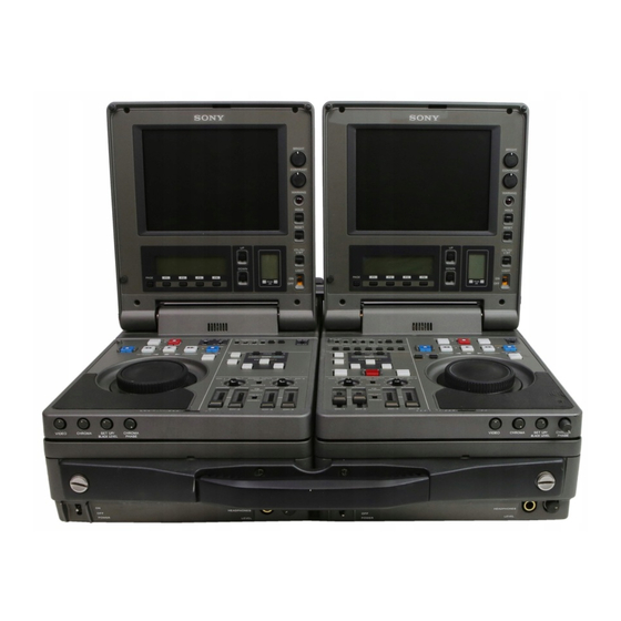
1-3 Locations and Functions of Locations and Functions of Parts Parts This unit is comprised of the parts shown in the figure below. Top panel (see page 1-24) Connector panel (see page 1-20) Slide the lock release switch and pick up the display panel. How to open the Display panel display panel... -
Page 11: Display Panel
1-3-1 Display Panel 1 LCD monitor 2 BRIGHT (brightness)/ CONTRAST knob 3 WARNING indicator 4 Timecode operation buttons 5 CTL/TC/U-BIT button 6 LIGHT switch 7 METER switch 8 Audio level meter !£ PAGE button 9 UP and DOWN buttons !™ Sub LCD operation buttons F1 to F4 0 Sub LCD !¡... - Page 12 Locations and Functions of Parts 5 CTL/TC/U-BIT button 0 Sub LCD Alternately selects CTL (control), TC Displays time data, status information, (timecode), and U-BIT (user bits) as sub LCD menu, setup menu and error the time data used in editing and messages.
-
Page 13: Control Panel
1-3-2 Control Panel Timecode and setup menu sections (see page 1-12) Editing section (see page 1-14) REC INHI switch (tape transport section) Audio control section (see page 1-16) Tape transport section (see page 1-8) Overview... - Page 14 Locations and Functions of Parts Tape transport section 4 EDIT button (recorder only) 3 REC/SEQ button 2 REC INHI indicator 1 PREROLL button Recorder 5 REC INHI switch !∞ REW button !§ EJECT button !¢ PLAYER/DMC and RECORDER buttons/indicators (recorder only) !£...
- Page 15 1 PREROLL button For details, see 4-2 “Sequential Press to run the tape up to the preroll Recording”. point (located in advance of the IN point by the amount of the preroll To monitor E-E mode time). You can set the preroll time You can monitor input signals in E-E using setup menu item 001.
- Page 16 Locations and Functions of Parts 6 SP TAPE switch (player only) 8 STOP button Selects the recording/playback format Press this button, lighting it, to stop when a Betacam SP cassette playback or recording. When you stop (including UVW cassette) is loaded in playback, the LCD monitor displays the player.
- Page 17 !¢ PLAYER/DMC and For details, see Chapter 5 “Shot Mark/Shot Data”. RECORDER buttons/indicators (recorder only) !¡ PLAY button Press to control a player connected to the REMOTE (9-pin) connector by Press this button, lighting it, to start playback. Recording starts when you remote control (the indicator lights).
- Page 18 Locations and Functions of Parts !§ EJECT button !¶ Cassette compartment Press to eject the cassette or open the Insert a cassette here. Press the EJECT cassette compartment !¶. The buttons button !§ to open the compartment. light while cassettes are being ejected. If you insert a cassette which cannot be used on this unit, the button flashes.
- Page 19 When the REMOTE is selected, you F-RUN: Timecode progresses can determine which tape transport continuously from the time when control buttons on the control panel this unit is powered on, are enabled. See setup menu item 006 regardless of the unit’s operating on page 6-3.
- Page 20 Locations and Functions of Parts Editing section 1 ASSEMBLE button and indicator (recorder only) 2 INSERT buttons and indicators (recorder only) 3 TRIM/GOOD SHOT buttons 4 ENTRY/SHIFT button 5 IN/OUT buttons 6 REVIEW button (recorder only) 7 AUTO EDIT button (recorder only) 8 PREVIEW button (recorder only) 9 DELETE button...
- Page 21 3 TRIM/GOOD SHOT buttons 6 REVIEW button (recorder only) Press the +/MARK or –/LIST buttons After executing an automatic edit, while pressing the IN/OUT buttons 5 press this button, lighting it to review or AUDIO IN button 0 to adjust edit the results of the edit.
- Page 22 Locations and Functions of Parts 9 DELETE button For details, see 3-5 “DMC Editing”. Press together with the IN/OUT buttons 5 or the AUDIO IN button This button is also used to delete shot 0 to delete edit points. The buttons marks from the tape.
- Page 23 1 AUDIO INPUT CH-1/CH-2 level 3 PB AUDIO PRESET/ adjustment knobs VARIABLE switch Make level adjustments by channel for Selects the level adjustment function analog input audio connected to the for playback audio. AUDIO INPUT CH-1/CH-2 PRESET: Preset to fixed levels. connectors on the connector panel.
-
Page 24: Front Control Section
Locations and Functions of Parts 1-3-3 Front Control Section 1 VIDEO knob 2 CHROMA knob 3 SET UP/BLACK LEVEL knob 4 CHROMA PHASE knob 5 POWER indicator 6 LEVEL knob 7 HEADPHONES jack 8 POWER switch 1 VIDEO knob 2 CHROMA knob Adjusts the video signal output level. - Page 25 3 SET UP/BLACK LEVEL knob 5 POWER indicator Lights when the POWER switch 8 is Adjusts the setup level (in 525/60 mode) and the black level (in 625/50 turned on. mode). This knob is a push switch. 6 LEVEL (speaker/headphones When you press it to bring it into the raised position, the setting becomes level) knob...
-
Page 26: Connector Panel
Locations and Functions of Parts 1-3-4 Connector Panel Analog audio/video input and output section 6 REF. VIDEO IN connectors and 75 Ω termination switch 7 VIDEO INPUT connectors and 75 Ω termination switch 8 VIDEO OUTPUT connectors 5 MONITOR OUTPUT L/R connectors 4 AUDIO OUTPUT CH-1/3 and CH-2/4 connectors 3 AUDIO INPUT CH-1/CH-2 connectors 2 AUDIO INPUT CH-1/CH-2 level switches... - Page 27 4 AUDIO OUTPUT CH-1/3 and 6 REF. VIDEO IN (reference CH-2/4 connectors (XLR 3-pin, video signal input) connectors (BNC type) and 75 Ω termination switch male) Output the audio signals of the Input a video signal with color burst channels selected with the LINE OUT (VBS) or monochrome video signal in the sub LCD menu.
- Page 28 Locations and Functions of Parts Digital signal/timecode/remote control/power input and output section 4 TC OUT connector 3 DC IN connector 2 TC IN connector 1 REMOTE connector Cable clamps 8 SDI IN connector 7 SDI OUT connectors 6 DC OUT connector 5 AUX connector 1 REMOTE (9-pin remote control) 2 TC IN (timecode input)
- Page 29 5 AUX connector Power supplied through this connector is used on a priority basic even when This connector is used only for you have connected a battery pack or service. AC-DN2(A) AC Adaptor to the 6 DC OUT connector battery connector on the top panel. This connector supplies power to the For more information, see section 2-1 BVR-3 Remote Control Unit.
-
Page 30: Top Panel
Locations and Functions of Parts 1-3-5 Top Panel Slide the covers off while pressing the levers. 2 BREAKER button 1 Battery connector 3 Shoulder belt attachment fixture 1 Battery connector 2 BREAKER button Connect a BP-L60(A)/L90(A) Battery When excess power flows inside the Pack, DC-L90 Battery Adaptor, or unit, breakers activate to protect the AC-DN2(A) AC Adaptor. -
Page 31: Power Preparations
2-1 Power Preparations This unit can be powered by batteries 2-1-2 Using the BP- or AC power. L60(A)/L90(A) Battery Pack Note If you attach or remove batteries or This unit can be operated for about 90 AC adaptors incorrectly, they may fall minutes at normal temperature on two down and cause body injury. -
Page 32: Using The Bp-90(A) Battery Pack
Power Preparations 2-1-3 Using the BP- 90(A) Battery Pack Different battery adaptors are used when mounting the BP-90(A) on the top panel of this unit and when connecting it the DC IN connector. This unit can be operated for about 60 minutes at normal temperature on a fully charged BP-90(A) Battery Pack. -
Page 33: Using Ac Power
When an external battery pack is Attach the DC-L90 to the top almost exhausted panel of this unit. If an internal battery pack is already Use the same method that you use mounted, disconnect the external to attach the BP-L60(A)/L90(A). battery pack by pulling its DC power For details, refer to “To attach cord out from the DC IN connector. - Page 34 Power Preparations Insert the V-wedge shoe on the POWER switch: ON AC-DN2(A) in the V-groove on AC power the player and slide the AC- cord DN2(A) until the battery charging (supplied AC-550/550CE connector is connected to the with AC- battery connector. 550/550CE) To AC Battery charging...
- Page 35 To DC output connector To DC IN connector Recorder Player DC cable (supplied with the AC-DN2(A)) Supply the AC-DN2(A) with AC power. For procedure on AC power supply to the AC-DN2(A), refer to the manual for the AC-DN2(A). Preparations...
-
Page 36: Connection
Power Preparations 2-2 Connection The figure below shows how to connect the player and recorder for editing. Recorder Player Reference video signal REF. VIDEO 75Ω termination REF. VIDEO 75Ω termination switch: ON switch: OFF REMOTE REMOTE SDI IN SDI OUT 1 REF. -
Page 37: Handling Cassettes
2-3 Handling Cassettes To record with this unit, you can use 2-3-1 Loading/Ejecting half-inch width Betacam SX S Cassettes cassettes, Betacam SP S cassettes (metal tape), or UVW S cassettes (metal tape). To load a cassette Usable Cassettes Betacam SX BCT-12SX/22SX/32SX/ 60SX Betacam SP... - Page 38 Handling Cassettes If “ERROR-10” appears in the To eject the cassette sub LCD This means that there is condensation inside the unit. For the steps to take in this case, see “Moisture Condensation” (page A-2). If there is slack in the tape Take up the slack by rotating the reels in the directions shown by the arrows in the figure, keeping one reel fixed by...
- Page 39 If there is no choice but to remove the cassette manually Manual eject knob Remove the cassette manually when battery power falls to below about 9 Note Power the unit off before removing the cassette manually. If the unit is powered, the drums may rotate and cause body injury.
-
Page 40: Preventing Accidental Erasures
Handling Cassettes 2-3-2 Preventing Accidental Erasures To make it impossible to accidentally erase or record over the contents of a cassette, press in the erasure prevention plug. Return the plug to its original position when you want to record on the cassette again. Cassette Erasure prevention plug 2-10... -
Page 41: Setting Reference Video Signals
2-4 Setting Reference Video Signals Reference video signal for servo This section explains how reference lock synchronization video signals for synchronization of video output and servo lock are Servo lock can be synchronized with selected according to settings made an external reference video signal, with this unit. - Page 42 Setting Reference Video Signals Reference video signals in editing When the OUT REF is set to REF, the Select AUTO2 when the external signal shown in the table below is reference video signal is not selected, depending on whether setup synchronized with the input video menu item 309 is set to AUTO1 or signal.
-
Page 43: Setting Timecode
2-5 Setting Timecode There are four ways to record For more information about timecode timecode. generator settings, see the setup menu “Item 600 series: timecode generator INT/EXT PRESET/REGEN settings” (page 6-20). switch switch PRESET For more information about playback REGEN timecode settings, see page 4-4. -
Page 44: Setting An Initial Value And Recording Timecode
Setting Timecode 2-5-1 Setting an Initial Value and Recording Timecode Set the switches and sub LCD menu To set an initial timecode items as shown below. value Perform the following procedure. RESET button INT/EXT: INT PRESET/REGEN: PRESET F-RUN/R-RUN: Either position 3,4,5,6 TC GENERATOR PRESET... - Page 45 Select the digit to set by rotating To set user bits the jog dial. You can record up to 8 hexadecimal The flashing digit changes to the digits of information (date, time, event digit on the right when you rotate number, etc.) in the timecode track.
-
Page 46: Synchronizing The Internal Timecode Generator With An External Signal
Setting Timecode 2-5-2 Synchronizing the Internal Timecode Generator with an External Signal Use this method to synchronize multiple VTRs with an external timecode generator, and when you want to record the playback timecode signals of an external VTR without deterioration in the signal waveform. You can synchronize the internal timecode generator with either of the following kinds of external timecode. -
Page 47: Synchronizing The Internal Timecode Generator With Playback Timecode - Timecode Recording During Auto Editing
2-5-3 Synchronizing the Internal Timecode Generator with Playback Timecode –Timecode Recording during Auto Editing Set switches and sub LCD menu items Sub LCD menu settings as follows. Item Setting VITC ON/OFF Desired position (home page) (ON when recording VITC) VITC/LTC/AUTO VITC or LTC, (home page) depending on which... -
Page 48: Recording External Timecode Without Regeneration
Setting Timecode 2-5-4 Recording 2-5-5 First Edit Function External Timecode without Regeneration The first edit function automatically creates a base tape for insert editing. Set the timecode value for the start of When this method is used, the internal recording in setup menu item 614. timecode generator is not affected by You can also specify the number of the external timecode. -
Page 49: Sub Lcd Menu
2-6 Sub LCD Menu Information about the settings and operating status of the unit is displayed in the sub LCD. 2-6-1 Displays on the Home Page of the Sub LCD Menu The home page of the sub LCD menu is displayed when you power the unit 1 Channel condition/input video level display 2 Time data display 3 VITC/LTC display... - Page 50 Sub LCD Menu 1 Channel condition/input video During E-E: The timecode to be level display recorded, when it has been read. Depending on the unit’s operating 4 525/625 display status, one of the following is displayed here. Displays 525 when the unit is being COND: Displayed during playback.
- Page 51 7 Audio settings page display 0 Source video signal display To select one of the groups of the You can select CMPST (composite) or audio settings pages (AU-1 to AU-4) SDI as the source video signal by or MIX/SWP, press operation button pressing operation button F4 to F1 to highlight this display, then press highlight this display and then...
-
Page 52: Sub Lcd Menu Basic Operations
Sub LCD Menu 2-6-2 Sub LCD Menu Basic Operations To switch between menu To select an item pages Display the page that contains the item In addition to the home page, the sub you want to select, then press the LCD menu has pages that allow you to operation button, F1 to F4, that is make settings for input and output of... - Page 53 Home page 01 : 23 : 45 : 01 AU-1 VITC ON AU-1 PAGE PAGE PAGE AU-2 General settings Video 1/2 PAGE PAGE PAGE Audio 1-1 PAGE Audio 2-1 Home Video 2/2 PAGE Audio 1-2 PAGE Home PAGE MIX/ Audio 1-3 PAGE a) When the unit is first powered on, and when you...
-
Page 54: Input And Output Settings For Video And Audio Signals (Sub Lcd Menu)
2-7 Input and Output Settings for Video Input and Output Settings for Video and Audio Signals (Sub LCD Menu) and Audio Signals (Sub LCD Menu) Using the sub LCD menu, you can For more information about basic sub make channel settings and adjust the LCD menu operations, see section 2- input and output characteristics of 6-2 “Sub LCD Menu Basic... - Page 55 Audio settings page 1-2 MIX/SWAP [AU-1-2] 1*IN-1 2 IN-1 3 IN-1 4 IN-1 IN-2 *IN-2 IN-2 IN-2 IN-3 IN-3 *IN-3 IN-3 IN-4 IN-4 IN-4 *IN-4 Item Setting MIX/SWAP Select up to two audio input signals (IN-1 to IN-4) to be assigned to CH 1 to 4 channels 1 to 4.
-
Page 56: Making Settings In The Audio Settings Subpages
Input and Output Settings for Video and Audio Signals (Sub LCD Menu) Item Setting LINE OUT Select channels 1/2 or 3/4 as the line out channels. MONITOR Select FIX for an output level determined according to the setting (either PRESET or VARIABLE) of the PB AUDIO PRESET/VARIABLE switch of the control panel, or VAR for an output level linked also to the LEVEL knob on the front control section. - Page 57 COND VITC SX 50 BATT 01 : 23 : 45 : 01 MIX OFF 1+2m1 1+2m2 /OUT PAGE To switch pages Press the F4 button. An output monitor settings page like the one below appears. COND VITC SX 50 BATT 01 : 23 : 45 : 01 L/R=1/2 1˜2...
- Page 58 Input and Output Settings for Video and Audio Signals (Sub LCD Menu) Contents of the audio settings subpages Output monitor settings page When you change the settings of the By pressing operation buttons F1 to audio settings subpages, the settings of the AU-1 page change as well, and F3, you can make the following three vice versa.
-
Page 59: Making Settings In The Video Settings
2-7-3 Making Settings in the Video Settings Pages The following tables show the items that can be set in the video settings pages. Video settings page 1/2 VIDEO CONFI PREREAD VIN TRIG VIDEO ZEBRA OUT REF PRESET INPUT Item Setting VIN TRIG Select whether or not to output a GPI signal from pin 5 of the AUX connector at the IN points of a video auto-edit (excluding audio split editing). - Page 60 Input and Output Settings for Video and Audio Signals (Sub LCD Menu) Video settings page 2/2 AUD SG VID SG SILNC CB75 Y/C DLY PROCESS CONTROL SYNC PH SC PH PRESET PANEL a) For 525 mode, CB100 for 625 mode. Item Setting PROCESS...
- Page 61 Item Setting VID SG Select the test signal to be output from the VTR’s internal test signal generator. The internal test signal generator operates and outputs the selected test signal. This signal can also be recorded. CB100 (625 mode) : 100% color bar signal CB75 (525 mode) : 75% color bar signal CB75R: 75% color bar signal (reverse) BOW: Bowtie signal...
-
Page 62: General Settings Page Of The Sub Lcd Menu
2-8 General Settings Page of the Sub Input and Output Settings for Video and Audio Signals (Sub LCD Menu) LCD Menu The general settings page cotains the items shown below. 1 SUPER setting 2 CAPSTAN setting 3 DF/NDF setting (in 525 mode) 4 BACKLGT setting SUPER CAPSTAN... - Page 63 2 CAPSTAN (capstan lock) setting 7 BAT-NE (battery near end) Set the capstan servo lock mode. setting 2F: Lock the capstan servo on 2 For alarms that alert you when the end fields. When performing picture of power as specified in the battery end setting 6 is near, specify a shift under the 525 system, set setup menu item 712 to ON (see...
-
Page 65: Selecting An Edit Mode
3-1 Selecting an Edit Mode You can do two types of editing on Selecting assemble mode this unit: assemble editing and insert editing. This section provides an Press the RECORDER button on outline of each type and explains how the recorder control panel. to select an edit mode. -
Page 66: Insert Editing
Selecting an Edit Mode Selecting insert mode 3-1-2 Insert Editing Press the RECORDER button on In insert editing, you insert video, the recorder control panel. audio, and timecode at desired positions on an already recorded tape. The RECORDER indicator lights. You can insert all three types of data at the same time, or insert one of the Press one or more of the INSERT... -
Page 67: Finding Edit Points - Search
3-2 Finding Edit Points – Search Variable mode Playback in search mode using the jog and shuttle dials allows finding edit Playback speed is determined by the points quickly. rotation angle of the shuttle dial On this unit, you can perform search between ±1 times normal speed (47 in the following three modes: jog, steps). - Page 68 Finding Edit Points – Search Switching from variable to shuttle mode Press the search button for 1 or more seconds. To switch between normal playback and search modes Press the PLAY and search buttons alternately. As factory default setting, rotating the jog or shuttle dial switches to search mode at any time except during recording and editing.
-
Page 69: Setting Edit Points
3-3 Setting Edit Points In editing operations, there are four Press the IN button together with edit points: an IN point and an OUT the ENTRY/SHIFT button at the point on the recorder side, and an IN point you want to set as the IN point and an OUT point on the player point. -
Page 70: Checking Edit Points
Setting Edit Points To display the duration 3-3-2 Checking Edit between two edit points Points From among the recorder and player You can check the time data of edit IN buttons (or AUDIO IN buttons) points and the duration between two and OUT buttons, press two of the edit points by displaying them in the buttons together. -
Page 71: Previewing Edit Results
Use the following procedures to cue To preroll the tape up an edit point or preroll the tape. Press the recorder or player PREROLL button. To cue up an edit point Press and hold the recorder or player IN or OUT button, and press the recorder or player PREROLL button while holding the IN or OUT button. -
Page 72: Modifying Edit Points
Setting Edit Points 3-3-5 Modifying Edit Points Once you set edit points, you can delete them or modify them as required in units of one frame. When edit points have been set incorrectly, for example when an OUT AUDIO IN EDIT –... -
Page 73: Setting Edit Points Using The Recorder Only
While pressing the recorder or To deleting an edit point player IN or OUT button, depending on the edit point that Proceed as follows. you want to modify, press a TRIM button (+/MARK or –/LIST) on the same side of the control panel. The edit point time data is displayed. -
Page 74: Executing An Edit
Executing an Edit 3-4 Executing an Edit 3-4-1 Outline of Editing Operations The figure below shows how the recorder and player operate during edit. Tape transport Postroll point Preroll point OUT point IN point Recorder Preroll Postroll Assemble editing Playback Over- recording Insert editing... -
Page 75: Starting An Edit
Monitoring signals during an edit Just as during a preview, you can see the video in the recorder side LCD monitor and listen to the audio through the recorder side speaker. The figure below shows the video and audio signals which can be monitored. AUDIO IN –... -
Page 76: Redoing An Edit
Executing an Edit 3-4-3 Redoing an Edit 3-4-4 Displaying the Results of Editing Edit point data is retained even after you execute an edit, until you set new This unit can save the editing results edit points. of the most recent 20 events in You can redo an edit after modifying memory. - Page 77 ASM: assemble editing Changing the settings V: video insert editing 1 to 4: audio insert editing You can change the settings of the edit T: Timecode insert editing points and the edit preset. Displaying more detailed Display the event information list. information Rotate the jog or shuttle dial to align Rotate the jog or shuttle dial to...
-
Page 78: Dmc Editing
Executing an Edit 3-5 DMC Editing Using the Betacam SX format on the Playback speed can be controlled player allows you to perform variable- between ±1 times normal speed. speed editing by controlling the playback speed of the player from the recorder. -
Page 79: Setting Edit Points And Playback Speeds
3-5-2 Setting Edit Points and Playback Speeds Perform the following procedure. 2,4,6,7 2,5,6,7 REC INHI TC GENERATOR PREROLL REC SEQ EDIT METER INHI LOCAL PRESET F-RUN MENU CH-1/2 REMOTE REGEN R-RUN PB/EE CH-3/4 ASSEMBLE INSERT EJECT PLAY F FWD STOP SERVO STANDBY VIDEO... -
Page 80: Executing Dmc Editing
DMC Editing If the JOG/SHUTTLE indicator Press the PLAYER/DMC button goes out before the tape passes and set the IN point for the player. the OUT point The unit cannot store any more Note variations in playback speed. The You cannot set an OUT point for capacity of the playback speed the player. -
Page 81: Preread Editing
3-6 Preread Editing Video and audio signals (channels 1 Signals read in advance can be sent to to 4), already recorded onto the tape, mixers for mixing and can be returned can be used as an edit source for insert to the original channels or other audio editing. - Page 82 Make sure that no loop connection remains. • When using an external switcher, set setup menu item 727 (page 6-33) to EXT. • Some switchers cannot be used due to their delay time. For details, consult Sony service personnel. 3-18 Editing...
-
Page 83: Special Editing
3-7 Special Editing This section explains the following Press the recorder PREVIEW kinds of editing. button. • Quick editing • Continuous editing A preview starts. The points • Manual editing selected in step 1 are set as the IN points, and the IN buttons of the recorder and player light. - Page 84 Special Editing Press the AUTO EDIT button. The edit starts. While monitoring the picture, when you reach the point you want to set as the OUT point, press the player or recorder OUT button together with the ENTRY/ AUDIO IN AUDIO IN –...
-
Page 85: Manual Editing
3-7-3 Manual Editing Perform manual editing using the recorder. REC INHI TC GENERATOR PREROLL REC SEQ EDIT METER INHI LOCAL PRESET F-RUN MENU CH-1/2 REMOTE REGEN R-RUN PB/EE CH-3/4 ASSEMBLE INSERT EJECT SERVO PLAY F FWD STANDBY STOP VIDEO AUDIO CH-1 CH-2 CH-3... - Page 86 Special Editing Press the RECORDER button, Press the PLAY button at the lighting the indicator. point where you want to end the edit (the recorder OUT point). Use the jog or shuttle dial to find the point where the edit will start The edit ends but player playback (the recorder IN point), and stop continues.
-
Page 87: Recording And Playback
4-1 Recording This section describes recording of AUDIO INPUT CH-1/CH-2 knobs, external input signals. You can use monitoring the input levels indicated both the recorder and player for by audio level meter. recording. 4-1-2 Recording 4-1-1 Preparations for Operation Recording Confirm that the cassette type display Perform the following procedure. - Page 88 4-2 Sequential Recording This unit allows you to perform When you renew the cassette about sequential recording with the recorder every 1 hour, endless recording is and player. possible. When you perform overwrite recording using only two cassettes, the Use the following procedure. You can last two hours recording can be do control panel operations on the obtained at any time.
- Page 89 The player starts recording automatically when the remaining time of the recorder side tape reaches 2 minutes. The setting of Setup menu item 014 affects what happens when a tape ends. When AUTOMATIC OVERWRITE is selected Endless recording on the same cassette continues, overwriting on the previous contents.
-
Page 90: Preparations For Playback
Playback 4-3 Playback This section describes playback of Select the playback format on the tapes. player. For playback using the jog/shuttle To play back cassettes recorded dials, see 3-2 “Finding Edit Points in Betacam SP format –Search”. Set the SP TAPE switch to SP PB ONLY. To play back Betacam SP 4-3-1 Preparations for cassettes recorded in Betacam... -
Page 91: Playback Operation
To adjust audio playback level 4-3-2 Playback Set the PB AUDIO PRESET/ Operation VARIABLE switch to VARIABLE, and adjust using the Confirm the recording format of the PB AUDIO CH-1 to CH-4 level cassette (SX, SP or OX) indicated on adjustment sliders. -
Page 92: Capstan Override Playback
Playback Release the PLAY button when 4-3-3 Capstan Override the adjustment is completed. Playback The VTR returns to normal speed When playing back the same program playback and the SERVO on two VTRs, the capstan override indicator lights. function is convenient for frame synchronization of playback pictures. -
Page 93: Shot Mark/Shot Data
5-1 Overview of Shot Mark/Shot Data Function (2) Writing and deleting shot This unit can record shot marks or use marks shot marks recorded with Betacam SX camcorders (shot marker function). You can use the Shot Mark Operation The shot mark function enables quick menu to specify whether REC Start access to the marked points, for marks are recorded. -
Page 94: Shot Mark Operation Menu
Shot Mark Operations 5-1-2 Shot Mark Operation Menu To display the Shot Mark Operation SHOT MARK GO1:SEARCH TYPE - menu, press the MENU button while GO2:LISTING TYPE GO3:RS.MARK MODE pressing the TRIM+/MARK button. GO4:MARK IN REC shot1 The menu shown in the figure appears. The Shot Mark Operation menu is composed of four items, G01 to G04. -
Page 95: Reading Shot Data
5-1-3 Reading Shot Data Shot data is recorded continuously on The tape is played back, and the the tape during shooting. display shown below appears. To display shot data, press the PLAY button together with the ENTRY/ SHIFT button. Name of shooting device MODEL NAME DNW 0090 SERIAL NUMBER... -
Page 96: Shot Mark Operations
Shot Mark Operations 5-2 Shot Mark Operations Use local mode for shot mark To read shot marks from operations. (Remote control shot mark multiple cassettes operations are not possible.) You can read shot marks from multiple cassettes by exchanging the 5-2-1 Reading Shot cassettes. - Page 97 To write shot marks 5-2-3 Creating a Virtual Shot Mark To write shot marks in recording and assemble mode During playback or search, press and Under Shot Mark Operation menu hold the ENTRY/SHIFT button, and item G04, select the type of mark you press the TRIM+/MARK button while want to write.
- Page 98 Shot Mark Operations SHOT MARK (003/180) Current cursor position number/ TIME CODE total number of marks memorized 1. #R 10:02:35:01 S1 10:04:05:20 Timecode *3. #S2 10:05:35:12 4. #V 10:07:05:11 Mark type: R (REC Start), S1(Shot Mark 1), S2 (Shot Mark 2), V (Virtual Shot Mark), P (Post Mark) Memo mark Selection mark: Shows the cue up shot mark.
- Page 99 To display shot marks and shot data at the same time At one of the broken lines in the shot You can sort the marks in the list by mark list, rotate the jog or shuttle dial the information in shot data. For to move the selector mark ( * ).
-
Page 100: Deleting Shot Marks
Shot Mark Operations The mark selection screen 5-2-5 Deleting Shot appears. Marks Rotate the jog or shuttle dial to You can select shot marks from the select “SORTING LIST”. list and delete them from the tape. To delete shot marks, press the While pressing the Search button, TRIM+/MARK button and keep it rotate the jog or shuttle dial to... -
Page 101: Cueing Up A Mark
After sorting Before sorting SHOT MARK SHOT MARK (---/180) (---/180) Cassette 1 TIME CODE TIME CODE Cassette 1 *012345-DNW-0123-4567- *012345-DNW-0123-4567- 10:04:05:11 10:04:05:11 ---------------------------- ---------------------------- 10:07:05:02 10:09:05:11 Cassette 2-1 Cassette 3 10:08:35:04 10:10:35:24 ---------------------------- 10:10:36:00 10:09:05:11 ---------------------------- Cassette 3 Cassette 2 10:10:35:24 10:05:35:24 10:10:36:00... -
Page 103: Menu System Configuration
6-1 Menu System Configuration The menu system of this unit For detailed information about menu comprises the basic menu and operation relating to the hours meter, extended menu. see “Digital Hours Meter” (page A- • Basic menu This menu is used to make settings relating, for example, to the •... - Page 104 Basic Menu Item number Item name Settings 0S... 5S ...30S: Set the preroll time to between 0 PREROLL TIME and 30 seconds in steps of 1 second. A preroll time of at least 5 seconds is recommended when using this unit for editing. CHARACTER Adjust the horizontal screen position of the H-POSITION...
- Page 105 Item number Item name Settings DISPLAY Determines the kind of character information which INFORMATION is superimposed on output from the VIDEO SELECT OUTPUT 2(SUPER) connector and display on the monitor when the SUPER in the submenu is set to ALL/MENU. T&STA : Time data display information and the unit’s status.
- Page 106 Basic Menu Item number Item name Settings Determines the type of character information CHARACTER TYPE (timecode, etc) which is superimposed on output from the VIDEO OUTPUT 2(SUPER) connector and display on the LCD monitor. WHITE : White letters on a black background. BLACK: Black letters on a white background.
- Page 107 Item number Item name Settings SEQUENTIAL Select the mode for sequential recording by the RECORD MODE recorder and player. OFF : No sequential recording. MANUAL CASSETTE REPLACE: Do sequential recording one time. Exchange the cassettes when one sequential recording finishes. AUTOMATIC OVERWRITE: Do sequential recording, overlaying previously recorded contents.
- Page 108 Basic Menu Output from the VIDEO OUTPUT 6-2-2 Basic Menu 2(SUPER) connector Operations When the SUPER in the sub LCD menu is set to ON (see page 2-31), the This section describes the basic menu same menu screen also appears on a displays and how to change the monitor connected to the VIDEO settings.
- Page 109 Turn the jog or shuttle dial depending Holding down the search button, on the current search mode (indicated turn the jog or shuttle dial. by JOG/SHUTTLE indicators). Turning the jog or shuttle dial in the The setting value changes at a rate clockwise direction increments the depending on the shuttle dial item number, and turning it in the...
- Page 110 Basic Menu Set menu item B20 RESET Select menu item 013. SETUP to ON. The LCD monitor shows the “PUSH SET BTN” appears in the following display. sub LCD, and “Push SET button” ITEM-013 appears on the LCD monitor. 525/625 SYSTEM SELECT Press the SET button.
- Page 111 Holding down the search button, Menu bank operations (menu turn the jog or shuttle dial to items B01 to B14) change the setting from “525” to “625”. This unit allows four different complete sets of menu settings to be The displays change as follows. saved in both 525 and 625 modes in what are termed “menu banks”...
- Page 112 Basic Menu 525 mode 625 mode Recall Recall Current Current Menu Menu Save menu menu Save bank 1 bank 1 settings settings Recall Recall Menu Menu Save Save bank 2 bank 2 Recall Recall Menu Menu Save Save bank 3 bank 3 Recall Recall...
-
Page 113: Extended Menu
6-3 Extended Menu 6-3-1 Items in the Extended Menu The extended menu contains the In the “Settings” column of the table, following items. the factory default settings are indicated by an enclosing box. Menu items in the 100s, relating to the control panels Item number Item name Settings... -
Page 114: Extended Menu Operations
Extended Menu Menu items in the 100s, relating to the control panels (continued) Item number Item name Settings REC INHIBIT LAMP Select whether or not to flash the REC INHI FLASHING indicator when recording is prevented though the REC INHI switch on the control panel is set to OFF. OFF : Light the REC INHI indicator. - Page 115 Menu items in the 100s, relating to the control panels (continued) Item number Item name Settings VARIABLE SPEED Select the playback speed range when carrying out LIMIT IN KEY PANEL playback in variable mode from the control panel of CONTROL this unit.
- Page 116 Extended Menu Menu items in the 200s, relating to the remote control interface Item number Item name Settings Select whether or not to use synchronized PARA RUN operation for two or more VTRs. DIS : No synchronized operation. ENA: Use synchronized operation. Note To use synchronized operation for two or more VTRs, set item 201 to “ENA”...
- Page 117 Menu items in the 300s, relating to editing operations (continued) Item number Item name Settings DMC INITIAL SPEED In DMC editing, select the initial tape speed which is set automatically. MANUAL : the speed determined by rotation angle of the shuttle dial PLAY: normal playback speed STILL: still playback speed ±0.03 to ±1: the speed selected in this range...
- Page 118 Extended Menu Menu items in the 300s, relating to editing operations (continued) Item number Item name Settings SERVO/AV Select the servo reference signal. REFERENCE SEL AUTO1 : During recording, an analog composite or digital input video signal is used as the servo reference signal.
- Page 119 Items 311 to 314 (settings for digital audio editing): If you use an editor (BVE-600, etc) or a remote controller which cannot control digital audio edit preset, select how to activate edit preset of each digital audio channel on the unit using the analog audio edit preset function of the editor or remote controller.
- Page 120 Extended Menu Menu items in the 300s, relating to editing operations (continued) Item number Item name Settings AUDIO EDIT MODE Specifies the type of editing for digital audio signals. CUT EDIT: Cut editing (discontinuity in audio signal may result at the editing point, causing noise.) CROSS FADE : Cross-fade IN/OUT FADE IN/OUT: Fade out and fade in...
- Page 121 Menu items in the 300s, relating to editing operations (continued) Item number Item name Settings Select whether or not to set the OUT point timecode AUTOMATIC IN for the IN point of the next auto-edit automatically ENTRY AFTER when an auto-edit is completed. AUTO EDIT OFF : Do not set the IN point timecode automatically.
- Page 122 Extended Menu Menu items in the 500s, relating to tape protection Item number Item name Settings STILL TIMER Select the time delay from the tape transport stopping (either the “STOP” mode” or the still playback mode in search mode) until the unit automatically switches to the tape protection mode, in order to protect the rotary heads and the tape.
- Page 123 Menu items in the 600s, relating to the time code generator (continued) Item number Item name Settings ID CODE PRESET Select whether or not to set the ID code. OFF : Do not set the ID code. ON: Set the ID code. To set the ID code: 1 Set this item to ON.
- Page 124 Extended Menu Menu items in the 600s, relating to the time code generator (continued) Item number Item name Settings TC OUTPUT SIGNAL Select the signal output from the TIME CODE OUT IN REGEN MODE connector during normal (×1) speed playback in the following two cases: •...
- Page 125 Menu items in the 600s, relating to the time code generator (continued) Item number Item name Settings TCG CF FLAG Select whether or not the color framing flag is set in the blank bit of the timecode. OFF : Color framing flag is not set. ON: Color framing flag is set.
- Page 126 Extended Menu Menu items in the 600s, relating to the time code generator (continued) Item number Item name Settings FIRST EDIT TC In First Edit mode, select whether or not to set the timecode value for the start when creating the base tape for editing (see page 2-18).
- Page 127 Menu items in the 700s, relating to video control Item number Item name Settings An E-E video signal is output delayed with respect SELECTION OF to the video input signal by the time for video circuit VIDEO/SYNC DELAY processing. With this item, select whether or not to delay the sync signal attached to the output video signal by an amount corresponding to the delay.
- Page 128 Extended Menu Menu items in the 700s, relating to video control (continued) Item number Item name Settings DECODE Y/C SEP Select the method of processing the input video MODE signal in the vertical blanking interval, independently for each line. Sub-item In 525 mode 12...20 LINE12...
- Page 129 Menu items in the 700s, relating to video control (continued) Item number Item name Settings FORCED VERTICAL The “Y-add” function is normally switched on INTERPOLATION automatically during noiseless variable playback. This item selects whether or not to force the “Y-add” function off.
- Page 130 Extended Menu Menu items in the 700s, relating to video control (continued) Item number Item name Settings VIDEO SETUP Set the video setup amounts to be removed from a REFERENCE LEVEL recording signal and Betacam playback signal, and (525 system) to be added to a composite output signal.
- Page 131 Menu items in the 700s, relating to video control (continued) Item number Item name Settings VIDEO ADJUST Select the variable range of the VIDEO and RANGE CHROMA knobs when the PROCESS CONTROL in the sub LCD menu is set to PANEL. –3~+3 : –3 dB to +3 dB WIDE: –...
- Page 132 Extended Menu Menu items in the 700s, relating to video control (continued) Item number Item name Settings INPUT VIDEO Switch blanking on or off for individual lines in the BLANK vertical blanking interval of an input video signal. The Y/C signal and odd/even fields are blanked simultaneously.
- Page 133 Menu items in the 700s, relating to video control (continued) Item number Item name Settings H BLANKING WIDTH Select the horizontal blanking width of a video output signal. NARROW: Digital blanking (narrow) Selecting NARROW is recommended for longer H- period of video when editing is performed between digital devices.
- Page 134 Extended Menu Menu items in the 800s, relating to audio control Item number Item name Settings DIGITAL AUDIO Set the digital audio muting conditions during MUTE IN SHUTTLE shuttle playback. MODE OFF : Not muted. CUEUP: Muted during cue-up or preroll operations. FULL: Muted in shuttle mode.
- Page 135 Menu items in the 800s, relating to audio control (continued) Item number Item name Settings AUDIO EDIT Set the output phase for the audio playback signal PREVIEW when any of the ASSEMBLE, VIDEO, AUDIO CH-1 SWITCHER to CH-4, and TC indicators is lit. INT : The audio playback signal output phase is the same as the output phase in the E-E mode.
- Page 136 Extended Menu Menu items in the 900s, relating to digital processing Item number Item name Settings Specify the “NO COMPRESSION” line (1 line in 1 NO COMPRESSION field) for video input . LINE OFF : No specification. 12H...21H (in 525 mode): Specify one of lines 12 to 9H...22H (in 625 mode): Specify one of lines 9 to Notes •...
- Page 137 6-3-2 Extended Menu Operations To access the extended menu, consult qualified Sony service personnel. How to access the extended menu Set switch 1 of the S201 on the internal SS-259 board to ON. S201 In the extended menu, you can carry out the same operations as in the basic menu except setting of sub-items.
-
Page 139: Appendixes
Insert the cleaning cassette. To clean the rotary and stationary heads, always use the special-purpose Press the EJECT button while Sony BCT-5CLN cleaning cassette. holding down PLAY button. Follow the instructions with the cleaning cassette carefully, as Head cleaning starts. -
Page 140: Moisture Condensation
Moisture Condensation If “ERROR-10” appears and the When the unit is suddenly moved WARNING indicator lights from a cold to a warm location, or immediately after powering the used in a very humid place, moisture unit on from the air can condense on the head- drum. -
Page 141: Digital Hours Meter
Digital Hours Meter H12: DRUM RUNNING mode The hours meter can display seven (resettable) items of information, in corresponding display modes, about the operational Same as H02 except that the count is history of the unit. Use it as a guide in resettable. - Page 142 Digital Hours Meter Displaying the hours meter LCD monitor CTL/TC/U-BIT button sub LCD Jog and shuttle dials MENU SET button PB/EE MENU button To display the hours meter Press the MENU button, then turn the jog or shuttle dial to display the required item in the LCD monitor and sub LCD.
-
Page 143: Specifications
Specifications The specifications are common to Analog Betacam playback time both the recorder and player except 30 minutes with otherwise mentioned. BCT-30MA Rewind time Approx. 3 minutes with BCT-60SX General Search speed Recording format Shuttle mode: Still to Betacam SX approx. - Page 144 Specifications Analog output Compression MPEG2 4:2:2 Profile @ A/D, D/A quantization Main Level 16 bits/sample Frequency response Analog composite recording/ 20 Hz to 20 kHz +0.5 dB/ playback –1.0 dB (0 dB at 1 kHz) Bandwidth (Y) Dynamic range 0 to 4.5 MHz+0.5 dB/ 88 dB or more (at 1 kHz, –3.0 dB (525 mode), emphasis on, 30 kHz...
- Page 145 Analog Betacam playback (DNW-A220, player) Video Oxide tape Metal tape Bandwidth 30Hz to 4.5MHz 30Hz to 4.1MHz +0.5 dB/–4.0dB +0.5 dB/–6.0dB R–Y/B–Y 30Hz to 1.5MHz 30Hz to 1.5MHz +0.5 dB/–3.0dB +0.5 dB/–3.0dB 51 dB or more 48 dB or more R–Y/B–Y 48 dB or more 45 dB or more...
- Page 146 Specifications Analog Betacam playback (DNW-A220P, player) Video Metal tape Oxide tape Bandwidth 25 Hz to 5.5 MHz 25 Hz to 4.0 MHz +0.5 dB/–4.0 dB +0.5 dB/–6.0 dB R–Y/B–Y 25 Hz to 2.0MHz 25 Hz to 1.5 MHz +0.5 dB/–3.0 dB +0.5 dB/–3.0 dB 46 dB or more R–Y/B–Y...
- Page 147 AUDIO INPUT CH-1/2 Processor adjustment range XLR 3-pin, female (2) –60/0/+4 dBu, high Video level impedance, balanced ±3 dB/–∞ to +3 dB TC IN BNC (1) selectable 0.5 to 18 Vp-p, 10 kΩ Chroma level DC IN XLR 4-pin ±3 dB/–∞ to +3 dB selectable Setup level (525 mode) ±30 IRE...
- Page 148 Specifications Remote connectors Note on liquid crystal display panel REMOTE D-sub 9-pin, female The liquid crystal display fitted to this unit is manufactured with high precision technology, giving a functioning pixel ratio of at least 99.99%. Thus a very small proportion Accessories supplied of pixels (at most 0.01%) may be 75Ω...
-
Page 149: Information Displayed On The Lcd Monitor
Information Displayed on the LCD Monitor To adjust the displayed text The LCD monitor displays setup menus, error messages, time data, and You can adjust the position, size, and information about the unit’s operating type of superimposed information status. using setup menu items 002, 003, 009, and 011. - Page 150 Information Displayed on the LCD Monitor 1 Time data type Time data 2 Timecode reader drop-frame mark (525 mode) 3 Timecode generator drop-frame mark (525 mode) 4 VITC data field mark T C R . 2 3 : 5 9 . 4 0 . 1 8 * S H U T T L E S T I L L 6 Operating mode...
- Page 151 6 Operating mode Note The display is divided into blocks A, Asterisks are displayed in this block B, and C, shown in the figure below. when timecode or user bits could not Block A: Operating mode be read correctly, for example as T * R, Block B: Servo lock status or tape U * R.
- Page 152 Information Displayed on the LCD Monitor Display Operating Mode Block A Block B TAPE UNTHREAD No cassette loaded STANDBY OFF Standby off mode T. RELEASE Tension release mode STOP Stop mode F. FWD Fast forward mode Rewind mode PREROLL Preroll mode PLAY Playback mode (servo unlock) PLAY...
- Page 153 To create new text data Enter the data in the data entry Use Setup Menu items 005 and 017 section. (page 6-3). Set Setup menu item 005 to To specify the data entry CHARCTER. position: Move the cursor to the right by pressing the F FWD button or to the left by For more information about menu pressing the REW button.
-
Page 154: Separating Into Two Vtrs
Separating into Two VTRs The following figure shows how to cause body injury. Follow the separate the unit into two VTRs. procedures described below for separation or combination. Note If you separate the unit or combine the recorder and player incorrectly, the recorder or player may fall down and Recorder Player... -
Page 155: Using The Shoulder Belt
To combine the recorder and player Reverse the steps for separation in a horizontal position. The figure shows how to fit the handle. Using the Shoulder Belt The following figures show how to fit To remove the shoulder belt the supplied shoulder belt. Note While pressing down the indication PRESS, move... -
Page 156: Using The Carrying Case
Using the Carrying Case The following figure shows how to Follow the procedures described pack the LC-DN220 Carrying Case below to pack the carrying case. (not supplied). Note If you pack the carrying case incorrectly, the unit or accessories may fall down and cause body injury. Cassettes Battery packs DNW-A220/A220P... -
Page 157: Using The Soft Carrying Case
Using the Soft Carrying Case LC-DN220SFT Carrying Case (soft case) is designed for one DNW-A220/ A220P unit or two DNW-A25/A25P units. Packing the case Removable pad Pocket for accessories DNW-A220/A220P When the AC-DN2(A) is attached Close the zipper. AC-DN2(A) You can stow the handle here. - Page 158 Using the Soft Carrying Case Placing the case on a flat surface Use the handle for lifting. A-20 Appendixes...
-
Page 159: Glossary
Glossary Assemble editing CONFI playback Digital VTR Editing in which new This refers to playback On a digital VTR, video video/audio is added in of the audio and video and audio signals are sequence to the end of signals immediately recorded on magnetic existing recorded video/ after recording, using the... - Page 160 Glossary Emphasis Non-drop frame mode The signal is Abbreviation of emphasized at high The number of frames of “Longitudinal Time frequencies. During the timecode and video Code”. This timecode is playback, it is de- run is not adjusted. recorded on a emphasized.
- Page 161 Reference video Servo signal Abbreviation of Sub A mechanism that A video signal which Carrier to Horizontal. controls the number and contains a sync signal or The phase of the phase of rotations of the sync and burst signals, subcarrier with respect to head drum or capstan.
- Page 162 Glossary Standby-off mode Sync Time code One of the stop modes. A reference signal The timecode is a tape In this mode, head drum consisting of vertical and position information rotation is stopped and horizontal sync signals signal that includes time the tape tension is used for synchronizing and frame data that are...
- Page 163 Unloading Video gain When the EJECT button Amount of amplification is pressed, the VTR for video signals, automatically winds the expressed in decibels tape back into the (dB). cassette case. Also called “Unthreading”. VITC Abbreviation of User bits “Vertical Interval Time These are also referred Code”.
-
Page 165: Index
Index Control panel 1-7 setup menu items 6-11 displaying 1-6, 2-19 AC adaptor BACKLGT (sub LCD menu) resetting 1-5 AC-550/550CE 2-3 2-32 CTL/TC/U-BIT button 1-6 AC-DN2(A) 2-4 Battery 2-1 Cue-up 3-6 AC power 2-3 BP-L60(A)/L90(A) 2-1 Accessories A-10 BP-90(A) 2-2 AGC (sub LCD menu) 2-24 connector 1-24 ASSEMBLE button/indicator... - Page 166 Index modifying 3-8 MONITOR (sub LCD menu) search 3-3 2-26 setting 3-5 MONITOR L/R (sub LCD shot mark position 5-7 menu) 2-26 IN/OUT buttons 1-15 time data display 3-6 MONITOR OUTPUT L/R IN/OUT points 3-5 EDIT button (recorder) 1-9 connectors 1-21 INSERT buttons/indicators E-E mode 1-9 Monitor output switch 1-13...
- Page 167 Sequential recording 4-2 STOP button 1-10 SERVO indicator 1-11 Sub LCD 1-6 Servo lock 1-11, 2-32, 6-11 display 2-19 reference video signal 2-10 operation buttons F1 to F4 Quick editing 3-19 SET button 1-13 SET UP/BLACK LEVEL knob Sub LCD menu 1-19 audio settings page 2-24 Setup level (525/60 mode)
- Page 168 Index Timecode generator VIDEO OUTPUT connectors external synchronization 1-21 2-16 2 (SUPER) connector A-11 holding the progress 1-5 VIN TRIG (sub LCD menu) setup menu item 6-20 2-29 Time data VITC display 2-20, 3-6 VITC/LTC (sub LCD menu) selection 1-6, 4-4 2-20 Top panel 1-24 VITC/LTC/AUTO (sub...
- Page 169 The material contained in this manual consists of information that is the property of Sony Corporation and is intended solely for use by the purchasers of the equipment described in this manual. Sony Corporation expressly prohibits the duplication of any...
- Page 170 Sony Corporation Communication System Solutions Network Company Printed in Japan DNW-A220/A220P 2000.09.13 (SY) ©1997 3-861-441-08(1)
Need help?
Do you have a question about the BETACAM SX A220P and is the answer not in the manual?
Questions and answers