Table of Contents
Advertisement
Quick Links
Advertisement
Table of Contents

Related Manuals for National Instruments 9503


Summary of Contents for National Instruments 9503
- Page 1 NI-9503...
- Page 2 USER MANUAL AND SPECIFICATIONS NI 9503 Stepper Drive Français Deutsch ni.com/manuals...
-
Page 3: Safety Guidelines
This document describes how to use the National Instruments 9503 module and includes specifications and pin assignments for the NI 9503. Visit and enter ni.com/info rdsoftwareversion determine which software you need for the modules you are using. For information about installing, configuring, and programming the system, refer to the system documentation. -
Page 4: Safety Guidelines For Hazardous Locations
National Instruments for repair. Safety Guidelines for Hazardous Locations The NI 9503 is suitable for use in Class I, Division 2, Groups A, B, C, D, T4 hazardous locations; Class I, Zone 2, AEx nA IIC T4, and Ex nA IIC T4 hazardous locations; and nonhazardous locations only. - Page 5 . Each module is marked II 3G and is suitable for use in Zone 2 hazardous locations, in ambient temperatures of -40 °C ≤ Ta ≤ 70 °C. If you are 4 | ni.com | NI 9503 User Manual and Specifications...
-
Page 6: Electromagnetic Compatibility Guidelines
This product was tested and complies with the regulatory requirements and limits for electromagnetic compatibility (EMC) as stated in the product specifications. These requirements and limits are designed to provide reasonable protection against NI 9503 User Manual and Specifications | © National Instruments | 5... - Page 7 To ensure compliance with the applicable Caution regulatory requirements, product installation requires either special considerations or user-installed, add-on devices. See the product installation instructions for further information. 6 | ni.com | NI 9503 User Manual and Specifications...
-
Page 8: Special Guidelines For Marine Applications
In addition, take precautions when designing, selecting, and installing measurement probes and cables to ensure that the desired EMC performance is attained. NI 9503 User Manual and Specifications | © National Instruments | 7... -
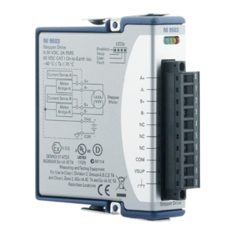
Page 9: Ni 9503 Hardware Overview
NI 9503 Hardware Overview The NI 9503 is a stepper motor drive for use with 2-phase hybrid stepper motors in either bipolar or unipolar winding configuration. It uses software-programmable control algorithms that reduce torque ripple, dampen high-speed resonance, and implements smoother motion during microstepping. - Page 10 Many applications do not require maximum holding torque when the motor is at rest, which means that the motor is wasting power. The amount of current reduction and delay before current NI 9503 User Manual and Specifications | © National Instruments | 9...
- Page 11 Position Angle Anti- Setpoint resonance voltage – Step Current Current Resolver Scheduler Loop Bridge Power Motor Controller Stage Generator Phase A & B Current Current Sense Fault Fault Monitor Detection 10 | ni.com | NI 9503 User Manual and Specifications...
-
Page 12: Connecting The Ni 9503
NI 9503 screw terminal. Do not turn on or plug in the motor DC power Caution supply until the screw-terminal connector is fully inserted. NI 9503 User Manual and Specifications | © National Instruments | 11... - Page 13 Figure 2. NI 9503 Connections Phase A+ Phase A– Phase B+ Phase B– Reserved Reserved Reserved Vsup (Chassis Ground) 12 | ni.com | NI 9503 User Manual and Specifications...
-
Page 14: Motor Power Signals
NI 9503 when it is enabled. Use a multiconductor cable with an overall shield and conductors of 20 AWG or larger for the motor power cable. NI 9503 User Manual and Specifications | © National Instruments | 13... - Page 15 The NI 9503 contains a highly efficient power stage. Two-phase stepper motors come in 4-, 6-, and 8-wire variations. You must wire the stepper motors in a 4-wire configuration as shown in Figure 3. Never connect unused stepper motor terminals Caution to pin 9 (Chassis Ground) or to each other.
- Page 16 (Higher Torque, Lower Speed) Phase A+ Phase A– Phase B+ Phase A+ Phase A– Phase B+ Phase B– Phase B– Reserved Reserved Reserved Vsup *NC = Not Connected NI 9503 User Manual and Specifications | © National Instruments | 15...
- Page 17 Figure 6. 6-Wire Half-Coil Stepper Motor Connection (Higher Speed, Lower Torque) Phase A+ Phase A– Phase B+ Phase A+ Phase A– Phase B– Phase B+ Phase B– Reserved Reserved Reserved Vsup *NC = Not Connected 16 | ni.com | NI 9503 User Manual and Specifications...
- Page 18 Figure 7. 8-Wire Series Stepper Motor Connection (Higher Torque, Lower Speed) Phase A+ Phase A– Red/Wht Phase A+ Phase A– Yel/Wht Phase B+ Phase B+ Phase B– Phase B– Yellow Reserved Reserved Reserved Vsup NI 9503 User Manual and Specifications | © National Instruments | 17...
- Page 19 Figure 8. 8-Wire Parallel Stepper Motor Connection (Higher Speed, Lower Torque) Phase A+ Phase A– Phase A+ Phase A– Phase B+ Red/Wht Phase B+ Phase B– Yel/Wht Reserved Phase B– Reserved Yellow Reserved Vsup 18 | ni.com | NI 9503 User Manual and Specifications...
- Page 20 Figure 9. 8-Wire Half-Coil Stepper Motor Connection Phase A+ Phase A– Phase B+ Phase A+ Phase A– Phase B– Phase B+ Phase B– Reserved Reserved Reserved Vsup *NC = Not Connected NI 9503 User Manual and Specifications | © National Instruments | 19...
-
Page 21: Wiring For High Vibration Applications
Refer to Figure 10 for an illustration of using ferrules. Figure 10. 10-Terminal Detachable Screw-Terminal Connector with Ferrule Terminated Wire Ferrule 20 | ni.com | NI 9503 User Manual and Specifications... -
Page 22: Led Indicators
NI 9503 topic in the LabVIEW Help, available by selecting Help» LabVIEW Help, for information about enabling the drive. Vsup The Vsup LED (green) illuminates when the motor DC power supply is properly connected. NI 9503 User Manual and Specifications | © National Instruments | 21... - Page 23 You can define the User LED (yellow) to meet the needs of your application. Use the User LED I/O node to turn this LED on and off. Refer to the NI 9503 topic in the LabVIEW Help, available by selecting Help»LabVIEW Help, for information about the NI 9503 User LED I/O node.
-
Page 24: Hot-Swap Behavior
Hot-Swap Behavior The NI 9503 is always disabled when it is first inserted in the chassis, regardless of whether Vsup is present or not. You can enable the drive using the Enable Drive method in software. Refer to the NI 9503 topic in the LabVIEW Help, available by selecting Help»LabVIEW Help, for more information about enabling the... -
Page 25: Cable Requirements For Emc Compliance
• Do not tie the motor case to the NI 9503 chassis ground. • Use only shielded cables to connect the NI 9503 to a motor and a power supply. • Terminate the motor and power supply cable shields to the COM terminal of the NI 9503. - Page 26 COM bypasses the ferrite as shown in Figure 11. Figure 11. NI 9503 Cable Connection NI 9503 Phase A+ Phase A– Motor Phase B+ Phase B– Shield Ferrites Motor DC Power Supply Vsup NI 9503 User Manual and Specifications | © National Instruments | 25...
- Page 27 Figure 12. Installing a Ferrite • Determine the clamp-on ferrite beads to install based on twice the motor cable and Vsup cable diameter. Order the appropriate ferrite beads from NI. 26 | ni.com | NI 9503 User Manual and Specifications...
-
Page 28: Specifications
Motor DC power supply (Vsup) ..+9 to +30 VDC Minimum phase inductance....1 mH Maximum phase inductance ..... 20 mH Type ..........PWM PWM frequency........ 20 kHz Current per phase......3 A RMS (4.24 A peak) NI 9503 User Manual and Specifications | © National Instruments | 27... -
Page 29: Drive Protection
Vsup greater than 40 V will result in damage Caution to the module. Overvoltage........>32 V Power Requirements Power consumption from chassis Active mode ....... 500 mW max Sleep mode ......... 2.5 mW max 28 | ni.com | NI 9503 User Manual and Specifications... -
Page 30: Physical Characteristics
(0.39 in.) of insulation stripped from the end Temperature rating ..... 85 °C min. Wires per screw terminal ....One wire per screw terminal, two when using 2-wire ferrule NI 9503 User Manual and Specifications | © National Instruments | 29... -
Page 31: Safety Voltages
Channel-to-COM ......0 to +30 VDC max, Measurement Category I Isolation Channel-to-channel ....None Channel-to-earth ground Continuous ......60 VDC, Measurement Category I Withstand ......1000 V , verified by a 5 s dielectric withstand test 30 | ni.com | NI 9503 User Manual and Specifications... - Page 32 (Other) are equivalent. These test and measurement circuits are not intended for direct connection to the MAINs building installations of Measurement Categories CAT II, CAT III, and CAT IV. NI 9503 User Manual and Specifications | © National Instruments | 31...
-
Page 33: Hazardous Locations
Europe (DEMKO) ......Ex nA IIC T4 Gc Power Supply Requirements Safety and Hazardous Locations Standards The NI 9503 is designed to meet the requirements of the following standards of safety for electrical equipment for measurement, control, and laboratory use: •... -
Page 34: Electromagnetic Compatibility
FCC 47 CFR Part 15B: Class A emissions • ICES-001: Class A emissions For the standards applied to assess the EMC of Note Online Product Certification this product, refer to the section. NI 9503 User Manual and Specifications | © National Instruments | 33... -
Page 35: Online Product Certification
To obtain product certifications and the DoC for this product, visit ni.com/ , search by module number or product line, certification and click the appropriate link in the Certification column. 34 | ni.com | NI 9503 User Manual and Specifications... -
Page 36: Shock And Vibration
Operating temperature (IEC 60068-2-1, IEC 60068-2-2) ..-40 to 70 °C Storage temperature (IEC 60068-2-1, IEC 60068-2-2) ..-40 to 85 °C Ingress protection......IP 40 NI 9503 User Manual and Specifications | © National Instruments | 35... -
Page 37: Environmental Management
Our Environmental Impact web page at ni.com/environment This page contains the environmental regulations and directives with which NI complies, as well as other environmental information not included in this document. 36 | ni.com | NI 9503 User Manual and Specifications... -
Page 38: Waste Electrical And Electronic Equipment (Weee)
WEEE Directive 2002/96/EC on Waste and Electronic Equipment, visit ni.com/environment/ weee National Instruments (RoHS) National Instruments RoHS (For information ni.com/environment/rohs_china about China RoHS compliance, go to ni.com/ environment/rohs_china NI 9503 User Manual and Specifications | © National Instruments | 37... -
Page 39: Worldwide Support And Services
(EMC) and product safety. You can obtain the DoC for your product by visiting . If your product supports calibration, ni.com/certification you can obtain the calibration certificate for your product ni.com/calibration 38 | ni.com | NI 9503 User Manual and Specifications... - Page 40 United States, visit the Worldwide Offices section of to access the branch office ni.com/niglobal websites, which provide up-to-date contact information, support phone numbers, email addresses, and current events. NI 9503 User Manual and Specifications | © National Instruments | 39...
- Page 41 For patents covering National Instruments products/technology, refer to the appropriate location: Help»Patents in your software, the patents.txt file on your media, or the National Instruments Patent Notice at ni.com/patents . You can find information about end-user license agreements (EULAs) and third-party legal notices in the readme file for your NI product.
Need help?
Do you have a question about the 9503 and is the answer not in the manual?
Questions and answers