Table of Contents
Advertisement
Quick Links
N8151-50A/N8151-53
AIT
内蔵
Built-In AIT
取扱説明書 ......................
User's Guide
•
製品をご使用になる前に必ず本書をお読みください。
本ユーザーズガイドは熟読の上、大切に保管してくだ
さい。
• Make sure you read this manual before using the
product.
After reading this manual carefully,
store it in a safe place.
1
ページ
Page 57
...............
2-102-363-02(1)
Advertisement
Chapters
Table of Contents

Related Manuals for NEC N8151-50A


Summary of Contents for NEC N8151-50A
- Page 1 N8151-50A/N8151-53 内蔵 Built-In AIT 取扱説明書 ...... ページ User’s Guide Page 57 ....• 製品をご使用になる前に必ず本書をお読みください。 本ユーザーズガイドは熟読の上、大切に保管してくだ さい。 • Make sure you read this manual before using the product. After reading this manual carefully, store it in a safe place. 2-102-363-02(1)
-
Page 3: 商標について
Server™ 2003 Datacenter Edition operating system 、 および Microsoft Windows Server™ 2003 Web Edition operating system の略称です。 サンプルアプリケーションで使用している名称は、すべて架空のものです。実在する品名、団体名、個人名とは一 切関係ありません。 ご注意 ( ) 本ユーザーズガイドの内容の一部または全部を無断転載することは禁止されています。 ( ) 本ユーザーズガイドの内容に関しては将来予告なしに変更することがあります。 ( ) の許可なく複製・改変などを行うことはできません。 ( ) 本ユーザーズガイドは内容について万全を期して作成いたしましたが、万一ご不審な点や誤り、記載もれな どお気づきのことがありましたら、お買い求めの販売店にご連絡ください。 ( ) 運用した結果の影響については ( ) 項にかかわらず責任を負いかねますのでご了承ください。 © NEC Corporation 2004 ... -
Page 4: 安全にかかわる表示について
この取扱説明書は、必要なときすぐに参照できるよう、お手元に置いておくようにし てください。 「使用上のご注意」 を必ずお読みください。 使用上のご注意 〜必ずお読みください〜 本製品を安全に正しくご使用になるために必要な情報が記載されています。 安全にかかわる表示について 本ユーザーズガイドにはどこが危険か、どのような危険に遭うのか、どうすれば危険を避 けられるかなどについて説明されています。 本ユーザーズガイド、および警告ラベルでは危険の程度を表す言葉として、 「警告」 と 「注 意」 という用語を使用しています。それぞれの用語は次のような意味を持つものとして定 義されます。 警告 人が死亡する、または重傷を負うおそれがあることを示します。 火傷やけがなどを負うおそれや物的損害を負うおそれがあることを示 注意 します。 危険に対する注意・表示は次の 種類の記号を使って表しています。それぞれの記号は次 のような意味を持つものとして定義されています。 注意の喚起 この記号は危険が発生するおそれがあることを表 (例) します。記号の中の絵表示は危険の内容を図案化 したものです。 (感電注意) 行為の禁止 この記号は行為の禁止を表します。記号の中や近 (例) くの絵表示は、してはならない行為の内容を図案 化したものです。 (分解禁止) 行為の強制 この記号は行為の強制を表します。記号の中の絵 (例) 表示は、しなければならない行為の内容を図案化... -
Page 5: 記号とその内容
(本ユーザーズガイドでの表示例) 注意を促す記号 危険に対する注意の内容 危険の程度を表す用語 注意 電源が のまま取り付け・取り外しをしない 本体装置への取り付け・取り外しの際や、周辺機器との接続の際は 必ず主電源に接続している電源コードをコンセントから抜いてくだ さい。電源コードがコンセントに接続されたまま取り付け・取り外 しや接続をすると感電をするおそれがあります。 本ユーザーズガイドおよび警告ラベルで使用する記号と その内容 注意の喚起 発煙または発火のおそれがある 感電のおそれがあることを示し ことを示します。 ます。 指などがはさまれるおそれがあ 特定しない一般的な注意・警告 ることを示します。 を示します。 行為の禁止 特定しない一般的な禁止を示し 本製品を分解・修理・改造しな ます。 いでください。感電や火災のお それがあります。 行為の強制 本製品の電源プラグをコンセン 特定しない一般的な使用者の行 トから抜いてください。火災や 為を指示します。説明に従った 感電のおそれがあります。 操作をしてください。 使用上のご注意... -
Page 6: 安全上のご注意
安全上のご注意 本製品を安全にお使いいただくために、ここで説明する注意事項をよく読んでご理解し、 安全にご活用ください。記号の説明については巻頭の 『安全にかかわる表示について』 の説 明を参照してください。 全般的な注意事項 警告 人命に関わる業務や高度な信頼性を必要とする業務には使用しない 本製品は、医療機器・原子力設備や機器、航空宇宙機器・輸送設備 や機器など、人命に関わる設備や機器および高度な信頼性を必要と する設備や機器などへの組み込みやこれらの機器の制御を目的とし た使用は意図されておりません。これらの設備や機器、制御システ ムなどに本製品を使用した結果、人身事故、財産被害などが生じて も当社はいかなる責任も負いかねます。 煙や異臭、異音がしたまま使用しない 万一、煙、異臭、異音などが生じた場合は、ただちに本体装置の電 源を にして電源コードをコンセントから抜き、本製品の ケーブルを抜いてください。その後、お買い求めの販売店または保 守サービス会社にご連絡ください。そのまま使用すると火災の原因 となります。 針金や金属片を差し込まない 通気孔やカートリッジ挿入口から金属片や針金などの異物を差し込 まないでください。感電の危険があります。 注意 製品内に水や異物を入れない 製品内に水などの液体、ピンやクリップなどの異物を入れないでく ださい。火災や感電、故障の原因となります。もし入ってしまった ときは、すぐに本体装置の電源を にして電源コードをコンセン トから抜き、本製品の ケーブルを抜いてください。分解しないで 販売店または保守サービス会社に連絡してください。 使用上のご注意... - Page 7 電源・電源コードに関する注意事項 警告 ぬれた手で ケーブルを持たない ぬれた手で ケーブルの抜き差しをしないでください。感電するお それがあります。 注意 電源が のまま取り付け・取り外しをしない 本体装置への取り付け・取り外しの際や、周辺機器との接続の際は 必ず主電源に接続している電源コードをコンセントから抜いてくだ さい。電源コードがコンセントに接続されたまま取り付け・取り外 しや接続をすると感電をするおそれがあります。 中途半端に差し込まない ケーブルはしっかりと差し込んでください。中途半端に差し込む と接触不良のため発熱し、火災の原因となることがあります。また 差し込み部にほこりがたまり、水滴などが付くと発熱し、火災の原 因となるおそれがあります。 指定以外の接続をしない ケーブルの接続や配線は本ユーザーズガイドの説明に従って正し く行ってください。指定以外の接続や配線は火災や感電の原因とな るおそれがあります。 破損したケーブルを使用しない ケーブルを接続する前にコネクタが破損していたり、コネクタピン が曲がっていたり、汚れたりしていないことを確認してください。 破損や曲がっているコネクタおよび汚れたコネクタを使用すると ショートにより火災を引き起こすおそれがあります。 指定以外のケーブルを使用しない 本体装置と接続するケーブルは当社指定のものを使用し、接続先を よく確認してください。指定以外のケーブルを使用したり、指示と は異なる接続のまま使用したりすると火災を引き起こすおそれがあ ります。 使用上のご注意...
- Page 8 設置・移動・保管・接続に関する注意事項 注意 通気孔をふさがない 本製品の前面にある通気孔をふさがないでください。内部の温度が 上昇し、誤動作の原因となるばかりでなく、火災や感電の原因とな ります。 プラグを差し込んだままインタフェースケーブルの取り付けや取り 外しをしない インタフェースケーブルの取り付け/取り外しは本体装置の電源 コードをコンセントから抜いて行ってください。たとえ電源を にしても電源コードを接続したままケーブルやコネクタに触ると感 電したり、ショートによる火災を起こしたりすることがあります。 指定以外のインタフェースケーブルを使用しない インタフェースケーブルは、 が指定するものを使用し、接続す る製品やコネクタを確認した上で接続してください。指定以外の ケーブルを使用したり、接続先を誤ったりすると、ショートにより 火災を起こすことがあります。 また、インタフェースケーブルの取り扱いや接続について次の注意 をお守りください。 • ケーブルを踏まない。 • ケーブルの上にものを載せない。 • ケーブルの接続がゆるんだまま使用しない。 • 破損したケーブルを使用しない。 • 破損したケーブルコネクタを使用しない。 • ネジ止めなどのロックを確実に行ってください。 使用上のご注意...
- Page 9 お手入れに関する注意事項 警告 自分で分解・修理・改造はしない 本製品の分解や、修理・改造は絶対にしないでください。製品が正 常に動作しなくなるばかりでなく、感電や火災の危険があります。 本製品でお客様が行える分解は次の作業のみです。 次に記述する以外の分解は絶対にしないでください。 • ブラケットの取り外し/取り付け •DC ・信号ケーブルの取り付け/取り外し プラグを差し込んだまま取り扱わない お手入れは、本体装置の電源を にして、電源コードをコンセン トから抜き、本製品の ケーブルを抜いてください。たとえ電源を にしても、電源コードを接続したまま製品内の部品に触ると感 電するおそれがあります。 注意 中途半端に取り付けない ケーブルやインタフェースケーブルは確実に取り付けてくださ い。中途半端に取り付けると接触不良を起こし、発煙や発火の原因 となるおそれがあります。 使用上のご注意...
- Page 10 運用中の注意事項 注意 カートリッジ挿入口に手を入れない カートリッジ挿入口に手を入れないでください。手を挟まれたり、 巻き込まれたりしてけがをするおそれがあります。 雷がなったら触らない 雷が鳴りだしたら、 ケーブルに触れないでください。感電の原因 となります。 ペットを近づけない 本製品にペットなどの生き物を近づけないでください。排泄物や体 毛が製品内部に入って火災や感電の原因となります。 近くで携帯電話や 、 ポケットベルを使わない 本製品のそばでは携帯電話や 、 ポケットベルの電源を に しておいてください。電波による誤動作の原因となります。 使用上のご注意...
-
Page 11: 正しく動作させるために
正しく動作させるために 本製品を正しく動作させるために、次の点について注意してください。 データカートリッジの取り扱いに関する注意事項については、 「 データカートリッ ジ」 の章を参照してください。 ● 本製品のジャンパとその他の 機器のジャンパが重複しないように設定してくだ さい。 → 誤動作の原因となります。 TAPE MOTION LED ● 本製品前面にある が点滅しているときに本体装置の電源を にしないでください。 → 故障、およびバックアップデータの破損の原因となります。 ● 腐食性ガスの発生する場所、薬品類の近くや薬品類がかかるおそれのある場所に保 管しないでください。 → 部品が変形したり傷んだりして正常に動作しなくなるおそれがあります。 ● 強い振動の発生する場所に保管しないでください。 → 故障の原因となります。 ● 本製品にセットするデータカートリッジには、当社製の 「 データカートリッジ」 EF-2423 EF-2423S EF-2420L EF-2420 (型番: 、... -
Page 12: 本ユーザーズガイドについて
本ユーザーズガイドについて N8151-50A/N8151-53 本ユーザーズガイドは、 内蔵 を正しくセットアップし、使 用できるようにするための手引きです。内蔵 のセットアップを行う場合や日常使用す る上で、わからないことが起きたときにご利用ください。 本ユーザーズガイドは、内蔵 を安全に、正しくお使いになるための事柄 (セットアップ や日常の取り扱いおよび保守) と内蔵 で使用できるカートリッジ 「 データカートリッ ジ」 を正しくお使いになるための事柄 (取り扱い方法や保管方法) の つの章から構成されて います。 はじめて取り扱うときの読み方 本製品を梱包箱から取り出して、はじめて取り扱うときは次の順序で本ユーザーズガイド を参照して、セットアップをしてください。 箱の中身を確認する ....... 箱の中身について (→ ページ) 取り扱う上での注意事項を覚える ..使用上のご注意 (→ 〜 ページ) 内蔵 の部品の名前を覚える ....各部の名称と機能 (→... -
Page 13: 本文中の記号について
本文中の記号について 本文中では、次の記号を使って運用上の注意やヒントを示しています (安全上の注意事項 に関する記号については巻頭の説明をご覧ください) 。 製品の取り扱いや、ソフトウェアの操作で守らなければならない事柄や 特に注意をすべき点を示します。 知っておくと役に立つ情報や、便利なことなどを示します。 その他 第三者への譲渡について 本製品または本製品に添付されているものを第三者に譲渡 (または売却) するときは、次の 注意を守ってください。 ●本製品本体について 本製品を第三者へ譲渡 (または売却) する場合は、本ユーザーズガイドを一緒にお渡 しください。 ●その他の付属品について その他の付属品もセットアップするときなどに必要となりますので、一緒にお渡し ください。 テープ内のデータについて 使用していたテープに保存されている大切なデータ (例えば経営情報や企業の経理情報な ど) が第三者へ漏洩することのないように、お客様の責任において確実に処分しておいて ください。 このようなトラブルを回避するために使用しているバックアップソフトでデータを完全 消去し、確実にデータを処分することを強くおすすめします。データの消去についての 詳細はバックアップソフトの取扱説明書をご参照ください。 なお、データの処分をしないまま譲渡 (または売却) し、大切なデータが漏洩された場 合、その責任は負いかねます。 ●添付ソフトウェアについて 本製品に添付のソフトウェアを第三者に譲渡 (売却) する場合には、以下の条件を満 たす必要があります。 添付されているすべてのものを譲渡し、譲渡した側は一切の複製物を保持しないこと。... -
Page 14: 消耗品・製品の廃棄について
消耗品・製品の廃棄について 本製品、およびカートリッジの廃棄については各自治体の廃棄ルールに従ってください。 詳しくは、各自治体へお問い合わせください。 製品寿命について 本製品の製品寿命は 年です。 保証について 本製品には 『保証書』 が添付されています。 『保証書』 は販売店で所定事項を記入してお渡し しますので、記載内容を確認のうえ、大切に保管してください。保証期間中に故障が発生 した場合は、 『保証書』 の記載内容にもとづき無料修理いたします。詳しくは 『保証書』 をご 覧ください。 保証期間後の修理についてはお買い求めの販売店、最寄りの または の保守サー ビス会社に連絡してください。 本製品に対し保守契約を結ばれたお客様へ 本製品の保守停止時期は、製造打ち切り後 年になります。 使用上のご注意... -
Page 15: 箱の中身について
箱の中身について N8151-50A/N8151-53 内蔵 の梱包箱の中には、内蔵 本体以外にいろいろな付属 品が入っています。下図を参照してすべてがそろっていることを確認し、それぞれ点検し てください。万一足りないものや損傷しているものがある場合は、販売店に連絡してくだ さい。 N8151-50A/N8151-53 □ ブラケット ( 本) をネジ止め ( 本) した状態で 出荷しています。 □ フロッピ−ディスク □ クリーニング □ ネジ ( 本) □ ケーブル (デバイスドライバ) カートリッジ ※ 本製品を本体装置に 取り付けるときのみ に使用します。 □ 取扱説明書 □ 製品 □ 保証書... -
Page 16: Table Of Contents
目 次 商標について ............. 安全にかかわる表示について ........使用上のご注意 本ユーザーズガイドおよび警告ラベルで使用する 記号とその内容 ..........〜必ずお読みください〜 安全上のご注意 ............正しく動作させるために ........... 本ユーザーズガイドについて ........ はじめて取り扱うときの読み方 ....本文中の記号について ........ その他 ..............第三者への譲渡について ......消耗品・製品の廃棄について ..... 製品寿命について ........保証について ..........箱の中身について ..........特長 ................ 内蔵 について 使用できるカートリッジ ........各部の名称と機能 ..........製品前面... - Page 17 クリーニング ............リード/ライトヘッドのクリーニング ..本体のクリーニング ........データカートリッジの各部の名称 ......データカートリッジ EF-2423 EF-2423S ( 、 、 使用・保管・運搬条件 ........... EF-2420L EF-2420 、 ) に ラベル ..............ついて ラベル貼り付け位置 ........ラベルへの記入上の注意事項 ..... ライトプロテクト ..........取り扱い上の注意事項 ........... 使用上のご注意 ........... 一般的注意事項 ........... 使用禁止基準 ............寿命 ................ 重要なデータの保存について...
-
Page 18: Ait
内蔵 について 本製品のセットアップから取り付け、日常の取り扱い方法について説明します。 特長 本製品には、次のような特長があります。 Advanced Intelligent Tape (AIT) ● フォーマットを使ってデータをデータカート リッジに大容量記録できます。 ● データ圧縮機能により、次の容量のデータをデータカートリッジによって記憶できます。 Gbyte カートリッジ (型番) 記憶容量 ( ) N8151-50A AIT-1 EF-2420L 35 Gbyte 約 EF-2420 25 Gbyte 約 N8151-53 AIT-2 EF-2423 50 Gbyte 約 EF-2423S 36 Gbyte 約... -
Page 19: 使用できるカートリッジ
使用できるカートリッジ EF-2423 230 m EF-2423S 本製品には、当社製 データカートリッジ (テープ長 ) 、 170 m EF-2420L 230 m EF-2420 170 m (テープ長 ) 、 (テープ長 ) 、 (テープ長 ) をご使 用ください。当社製以外の データカートリッジを使用するとリード/ライトエラーの 原因となる場合があります。 各部の名称と機能 本製品の各部の名称と機能について説明します。 5.25 インチデバイスベイ実装タイプと インチデバイスベイ実装タイプ (ドライブ部の み) の、各部の名称と働きおよび設定方法は、共通です。 (以降、本ユーザーズガイドで 5.25 は、... -
Page 20: 製品背面
製品背面 1 電源コネクタ 本体の内蔵電源ケーブルを接続する (→ ページ) 。 2 ジャンパピン 内蔵 の設定をするピン (→ ページ) 。 コネクタ IDE Flat 本体の内蔵 ケーブルを接続する (→ ページ) 。 製品底面 スイッチ 内蔵 の設定をするスイッチ (→ ページ) 。 1 2 3 4 5 6 7 8 内蔵 について... -
Page 21: セットアップ
セットアップ Express5800 本製品を シリーズ製品などの 「本体装置」 に取り付けるまでの手順を説明し ます。 ブラケットの取り外し、取り付け方法 本製品を インチデバイスで使用するときは、左右のブラケットを取り外します。 ブラケットの取り外し プラスドライバを使ってネジを取り外すと、ブラケットが外れます。 ● 取り外したブラケットとネジは、大切に保管しておいてください。 ● このネジは、ブラケットを取り付けるときのみに使用します。 このネジはミリネジ (長さ 5 . 0 m m 、 ワッシャより下の長さ 4.0 mm 4.0 mm ) です。このネジより長いものを使用すると製品の故障 の原因となります。 ミリネジ 内蔵 について... - Page 22 ブラケットの取り付け 本製品のネジ穴とブラケットの長穴の後部を合わせ、プラスドライバを使ってネジを取り 付けます。 内蔵 について...
-
Page 23: 内蔵 Ait の設定
内蔵 の設定 〜ジャンパピンを使った設定〜 5.25 本製品を インチデバイスベイに取り付ける前に、本製品の設定を確認します。 本製品を含む デバイスは、 の設定が必要です。同じ バス上に接続されるデバイ スは、それぞれ異なる を設定しておかないと正しく動作しません。 MASTER SLAVE CABLE SELECT には、 「 」 、 「 」 、 「 」 の つがありますが、本製品は CD-ROM/RW MASTER SLAVE 標準装備の ドライブ ( ) と同一バス上に接続するため、 「 」 で使用してください。 は、本製品背面にあるデバイス設定ピンのピン 〜 を使って設定できます... -
Page 24: 内蔵 Ait の設定
内蔵 の設定 〜 スイッチを使った設定〜 本製品の底面にある スイッチでは次の設定を変更することができます。 DC Control (1) ● ( データ圧縮設定) ( 工場出荷時の設定は 「 」 ) DC Control (2) ● ( データ圧縮設定) ( 工場出荷時の設定は 「 」 ) 1 2 3 4 5 6 7 8 スイッチ 〜 予約済み スイッチ 7: DC Control (1) 8: DC Control (2) スイッチ... -
Page 25: 本体装置への取り付け
本体装置への取り付け 注意 電源が のまま取り付け・取り外しをしない 本製品の取り付け・取り外しの際や、ケーブルの接続の際は必ず主電源 に接続している電源コードをコンセントから抜いてください。電源コー ドがコンセントに接続されたまま取り付け・取り外しや接続をすると感 電をするおそれがあります。 本体装置機器等への設置方法例を以下に示します。 本体装置によってはレールを使用するものもあります。設置方法については、本体装置 の取扱説明書も参照してください。 CD-ROM/RW N8151-50A/ ドライブの下に N8151-53 内蔵 を取り付けます。 ● 本製品にレールを取り付ける場 Fig. 1 合は、 に示すフロントカ Fig. 1 バー側のネジ穴を使用してくだ Fig. 2 さい ( ) 。 (反対側も同様 フロントカバー に、片側 箇所、計 箇所をネ ジ止めしてください。) ネジ穴 レールが、フロントカバー部の... - Page 26 Fig. 3 フロントカバー レール ● 5.25 インチデバイスタイプ、 インチデバイスタイプのどちらの場合も使用するネ ジは同じです。 ● 必ず本製品に添付されているネジを使って固定してください。本製品 に添付のネジは、ミリネジ (長さ 5.0 mm 、 ワッシャより下の長さ 3.5 mm 3.5 mm ) です。添付のネジより長いものを使用すると製品の故障の 原因となります。 ミリネジ 注意 破損したケーブルを使用しない ケーブルを接続する前にコネクタが破損していたり、コネクタピンが曲 がっていたり、汚れたりしていないことを確認してください。破損や曲 がっているコネクタおよび汚れたコネクタを使用するとショートにより 火災を引き起こすおそれがあります。 Express5800/110Eh 120Ef 120Ga 本製品を 、 、 に接続する場合は、本体装置に添付 している ケーブルを使用してください。上記以外には本製品添付の ケーブルを...
- Page 27 本製品に添付の ケーブルを本製 CD-ROM/RW 品 お よ び 標 準 で 搭 載 さ れ て い る C D - R O M / R W ドライブに接続 し、マザーボード上の コネクタ 本製品 に接続します。 CD-ROM/RW ドライブとマザー ボードを接続していたケーブルは 取り外してください。また、取り 添付のケーブル 外したケーブルは大切に保管して おいてください。 コネクタ ケーブルはマザーボード上のコ マザーボード...
-
Page 28: バックアップソフト使用のご注意
バックアップソフト使用のご注意 http://www.express.nec.co.jp の 情報ページである 番街 ( ) の 「サポート情 Express5800/100 報」 − 「テクニカル情報 (テクニカルガイド) 」 − 「 シリーズテクニカルガ イド」 にありますバックアップ装置の<バックアップ装置対応ソフトウェア>を確認して ください。 webmaster@ace.comp.nec.co.jp 問い合わせ先: 内蔵 について... -
Page 29: テープデバイスドライバのインストール
のバック Windows Server 2003 アップ (システムツール) 、および のバックアップを使用する方 のみインストールしてください。 本体装置にテープデバイスドライバをインストールします。ドライバのインストールに は、添付のフロッピ−ディスクを使用します。あらかじめ用意しておいてください。 Windows 2000 ● でドライブをご使用のお客様 N8151-53 N8151-50A (本手順は、 の画面を用いて説明しています。 をご使用のお客様 SDX-520V SDX-420V は、 「 」 の部分が 「 」 となります。) 「スタート」 ボタンをクリックし、 「設定」 をポイントし、 「コントロールパネル」 をク リックして、 「システム」 をダブルクリックする。 「システムのプロパティ」 ダイアログボックスが表示されます。... - Page 30 「ドライバ」 タブをクリックし、 「ド ライバの更新」 ボタンをクリックす る。 「デバイスドライバのアップグレー ドウィザード」 が表示されます。 [次へ] ボタンをクリックする。 「ハードウェアデバイスドライバの インストール」 画面が 表示されま す。 「デバイスに最適なドライバを検索 する (推奨) 」 を選択し、 [次へ] ボタ ンをクリックする。 「ドライバファイルの特定」 画面が表 示されます。 添付のフロッピーディスクを挿入し ます。 内蔵 について...
- Page 31 「フロッピーディスクドライブ」 にの みチェックを入れ、 [次へ] ボタンを クリックする。 「ドライバファイルの検索」 画面が表 示されます。 ドライバファイルの検索が始まりま す。 a:¥win2000¥sw2ait.inf 「 」 が選ば れていることを確認し、 [次へ] ボタ ンをクリックする。 「デバイスドライバのアップグレー ドウィザードの完了」 画面が表示さ れます。 [完了] ボタンをクリックする。 「デバイスマネージャ」 ダイアログ ボックスで、 テープドライブユ ニットが表示されていることを確認 する。 内蔵 について...
- Page 32 Windows XP ● でドライブをご使用のお客様 N8151-53 N8151-50A (本手順は、 の画面を用いて説明しています。 をご使用のお客様 SDX-520V SDX-420V は、 「 」 の部分が 「 」 となります。) 「スタート」 ボタンをクリックし、 「コントロールパネル」 をクリックして、 「システム」 をダブルクリックする。 「システムのプロパティ」 ダイアログボックスが表示されます。 「ハードウェア」 タブをクリックし、 「デバイスマネージャ」 ボタンをクリックする。 「デバイスマネージャ」 ダイアログボックスが表示されます。 S O N Y 「 そ の 他 の デ バ イ ス 」 に 「...
- Page 33 「ソフトウェアを自動的にインス トールする (推奨) 」 を選択し、フ ロッピーを挿入して、 [次へ] ボタン をクリックする。 「下の一覧からハードウェアに最適 な ソ フ ト ウ ェ ア を 選 ん で く だ さ い。」 画面が表示されます。 a:¥winxp¥sxpait.inf 一覧から 「 」 を選択し、 [次へ] ボタンをクリック する。 「ハードウェアの更新ウィザードの 完了」 画面が表示されます。 「このドライバはデジタル署名され ていません」 と表示された場合で も、そのままインストールしてくだ...
- Page 34 「デバイスマネージャ」 ダイアログ ボックスで、 テープドライブユ ニットが表示されていることを確認 する。 インストールしたテープデバイスドライバは、システムの再起動後に有効になります。 内蔵 について...
- Page 35 Windows Server 2003 ● でドライブをご使用のお客様 N8151-53 N8151-50A (本手順は、 の画面を用いて説明しています。 をご使用のお客様 SDX-520V SDX-420V は、 「 」 の部分が 「 」 となります。) 「スタート」 ボタンをクリックし、 「コントロールパネル」 をポイントして、 「システム」 をクリックする。 「システムのプロパティ」 ダイアログボックスが表示されます。 「ハードウェア」 タブをクリックし、 「デバイスマネージャ」 ボタンをクリックする。 「デバイスマネージャ」 ダイアログボックスが表示されます。 S O N Y 「 そ の 他 の デ バ イ ス 」 に 「...
- Page 36 「ソフトウェアを自動的にインス トールする (推奨) 」 を選択し、フ ロッピーを挿入して、 [次へ] ボタン をクリックする。 「下の一覧からハードウェアに最適 なソフトウェアを選んで下さい。」 画面が表示されます。 a:¥win2003¥sxpait.inf 一覧から 「 」 を選択し、 [次へ] ボタンをクリック する。 「ハードウェアの更新ウィザードの 完了」 画面が表示されます。 「このドライバはデジタル署名され ていません」 と表示された場合で も、そのままインストールしてくだ さい。 [完了] ボタンをクリックする。 内蔵 について...
- Page 37 「デバイスマネージャ」 ダイアログ ボックスで、 テープドライブユ ニットが表示されていることを確認 する。 以上でテープデバイスドライバのインストールが完了しました。 内蔵 について...
-
Page 38: 取り扱い
取り扱い 本製品の取り扱い方法を説明します。 データカートリッジのセット ● 本製品にセットするデータカートリッジには、当社製の 「 データカートリッジ」 を 使用してください。当社製以外のデータカートリッジを使用するとリード/ライトエ ラーを起こすことがあります。 ● データカートリッジをセットしている間は、本体装置の電源を にしないでくだ さい。誤動作やデータの破壊の原因となります。 本体装置の電源を にした後、本 REPLACE TAPE LED 製品の と TAPE MOTION LED CLEAN- 、 ING REQUEST LED が消灯した ことを確認する。 防塵カバーを指で開く。 内蔵 について... - Page 39 データカートリッジを右図の向 き に し て 本 製 品 の デ ー タ カ ー ト リッジ挿入口に挿入する。 ある程度挿入するとデータカート リ ッ ジ は 自 動 的 に 本 製 品 内 部 に T A P E M O T I O N セットされ、...
-
Page 40: Ait データカートリッジの取り出し
データカートリッジの取り出し TAPE MOTION LED が点滅して いないことを確認する。 EJECT ボタンを押すと、テープの 巻き戻しが始まります (巻き戻しに 数分かかる場合があります) 。 巻き戻しが終わるとデータカート リッジは自動的に製品内から排出 されます。 EJECT バックアップソフト、 のロックにより、 ボタンを押してもカートリッジが排 出されない場合があります。バックアップソフトによるカートリッジ排出、またはしば E J E C T らく待ってから ボタンを押してください。それでも排出されない場合は、 EJECT ボタンを一定時間 ( 秒〜 秒) 押し続け、強制排出を行ってください。 防塵カバーを指で開く。 内蔵 について... -
Page 41: Led 表示
デ ー タ カ ー ト リ ッ ジ 挿 入 口 か ら データカートリッジを取り出し、 防塵カバーを閉める。 ● TAPE MOTION LED が点灯、または点滅している間は、本体装置の電源を に しないでください。誤動作やデータの破壊の原因となります。 ● 本製品にデータカートリッジを挿入したまま移動しないでください。本製品の故障の 原因となります。 ● バックアップ完了後は、カートリッジを取り出してください。 表示 本製品前面にある つの で、本製品や データカートリッジの状態を知らせます。 TAPE MOTION CLEANING REQUEST REPLACE TAPE 消灯 データカートリッジがセット... - Page 42 クリーニング 本製品を良い状態に保つために、定期的にクリーニングをしてください。 リード/ライトヘッドのクリーニング CLEANING REQUEST LED が点灯しているときは、本製品内部のリード/ライトヘッ ドを清掃してください。 EF-3237J 添付のクリーニングカートリッジ ( ) を 「取り扱い」 の 「 データカートリッジの セット」 で説明している手順で本製品にセットします。 クリーニングカートリッジをセットすると自動的にヘッドのクリーニングが開始されま す。 クリーニングが終了すると、自動的にクリーニングカートリッジが出てきます (開始から 約 秒後) 。クリーニングカートリッジを取り出してください。 : EF- ● 本製品のクリーニングには、当社製の 「 クリーニングカートリッジ (型番 3237J ) 」 を使用してください。当社製以外のクリーナーを使用すると故障の原因と なることがあります。 ● クリーニングカートリッジのテープ面を手で 触ったり、テープを巻き戻して使用したりし...
- Page 43 本体のクリーニング 本製品の外観が汚れたときは、やわらかい布に水または洗剤を含ませて軽く拭いてくださ い。 ベンジン、シンナーなど (揮発性のもの) の薬品で拭くと、変形や変色の原因となること があります。また、殺虫剤をかけた場合も変形や変色の原因となることがあります。薬 品が付着したら、早めに水を含ませた柔らかい布で拭き取ってください。 内蔵 について...
- Page 44 EF-2423 データカートリッジ ( 、 EF-2423S EF-2420L EF-2420 、 、 ) について データカートリッジの取り扱い方法について説明します。 データカートリッジの各部の名称 ラベル貼り付け位置 ラベル貼り付け位置 ライトプロテクト 取り付け/取り外し時 プラグ の取っ手 (反対側にも あります) 42 AIT データカートリッジについて...
- Page 45 使用・保管・運搬条件 ■ 使用条件 温度 〜 ℃ 湿度 〜 % (ただし、湿球の最高温度は ℃とします。) 放置時間 使用および保管環境条件以外の環境に データカートリッジがさら されていた場合には、使用および保管環境条件以外の環境にさらさ れていた時間より長く (最大 時間) 使用環境になじませてから使用し てください。温度勾配は最大 ℃/時間とします。 ■ 保管条件 温度 〜 ℃ 湿度 〜 % (ただし、湿球の最高温度は ℃とします。) 保管状態 データカートリッジは、保護ケースに入れて、フタをして保管し てください。置き方は水平、垂直どちらでもかまいません。 ■ 運搬条件 –40 温度 〜 ℃ 湿度...
- Page 46 ラベルへの記入上の注意事項 ● データカートリッジの内容を表示するために用いるラベルは簡単に取り換える ことができ、取り外した後に粘着物が残らないようなものを使用してください。 ● 内容の表示を変更するときは、消しゴムで消さず、必ずラベルを貼り替えてくださ INDEX い ( ラベルは データカートリッジに添付されています) 。 ● ラベルを貼るときは、前項で指定された位置に確実に貼り、さらに取り換える場合 は古いラベルを取り除いてから新しいラベルを貼ってください。 INDEX ● 指定の ラベル以外のものを使用する場合は、大きさが合ったものを使用し てください。 INDEX ● 添付の ラベルには、使用開始年月日を記入してください。 データカート リッジの寿命をチェックする目安となります。 ライトプロテクト ライトプロテクトプラグを右図のように EF-2423 設定すると、テープの内容が保護されま EF-2423S す。 書き込んだデータを消去したくないとき SAFE は、このプラグを 「 」 側 (書き込み 不可) に設定してください。また、プラ グを...
- Page 47 取り扱い上の注意事項 使用上のご注意 使用する前 ● 使用する データカートリッジが、外的損害を受けていたり、または変形した り、曲がっているときは、使用しないでください。 ● 製品の使用温湿度条件以外で保管されていた データカートリッジを使用する場 合は、使用温湿度条件以外にあった時間より長く (最大 時間) 、使用環境に持ち込 んでから使用してください。保管場所と使用場所の温度差が大きい場合は、一度に 持ち込むのではなく、温度変化が 時間に ℃以下になるようにして、 データ カートリッジを使用場所の温度になじませてください。 製品への装着 「 データカートリッジのセット」 での説明に従って データカートリッジをセットし てください。 データカートリッジを取り出した後の保護ケースは、しっかりと閉じ、 チリやホコリの少ない場所で保管してください。 使用した後 使用済みの データカートリッジは、必ず保護ケースに入れてチリやホコリの少ない場 所で保管してください。置き方は水平、垂直どちらでもかまいません。 一般的注意事項 ● テープに手を触れないでくださ い。また、テープカバーを開閉 テープカバー しないでください。 ● 磁気を発生するものを近づけな いでください。...
- Page 48 使用禁止基準 以下の項目に該当する場合は、新しい データカートリッジに取り替える必要がありま す。 ● 落下させるなど強い衝撃を与え、 データカートリッジが損傷を受けた場合。 強い衝撃を受けた場合、カートリッジが変形したり、欠けたりする場合がありま す。また、テープカバーが正常に開閉しなくなり、カートリッジが排出されないと いった障害の原因となります。 ● 清涼飲料、コーヒー、紅茶など液体、溶剤や金属粉、たばこの灰などで記録面が汚 れている場合。 この状態で データカートリッジを製品に挿入するとヘッドや製品を損傷したり、 汚したりすることになり、製品の故障の原因となります。また、ヘッドの汚れやキ ズに気づかず、新しい データカートリッジを製品に挿入すると、 データカー トリッジを汚したり、傷つけたりして被害を広げることになります。 寿命 テープの寿命は、温度・湿度、ヘッドクリーニング回数などによって左右されます。 毎日 回使用した場合は、使用開始より 年後、毎回使用していない場合でも、使用開始よ り 年後に交換をお願いします。また、エラーが頻繁に発生する場合は、その前に交換を お願いします。 データカートリッジの寿命管理として下記の手順を実施していただくことをお勧めし ます。 ● 新しい データカートリッジに管理番号を割り当て、その番号を データカー トリッジのラベルに記入しておきます。 ● データカートリッジ管理台帳を作り、使用日を記録し、 データカートリッ ジの使用年数と使用回数を見積もります。 ● 定期的に データカートリッジの管理台帳と標識ラベルを調べ、長く使用されて...
- Page 49 重要なデータの保存について 重要なデータまたはプログラムなどを保存する場合には、万一の場合に備えて、正副 巻 に保存することをお勧めします。 また、保存する際にはバックアップソフトのベリファイ機能を利用し、保存したデータの 確認も行うことをお勧めします。ベリファイ機能の利用方法については、各バックアップ ソフトの取扱説明書を参照してください。 こうしておけば、一方のテープがチリやホコリによるリードエラーを起こしても、もう一 方のテープから復旧でき、大切なデータやプログラムの消失を防げます。 データの 世代管理について ディスク上のデータを保存する場合は、保存したデータの 世代管理をお勧めします。 世代管理は、テープ 巻 ( 、 、 ) を使用して、ディスク上のデータを 日目はテープ に保存し、 日目はテープ に、 日目はテープ に保存していくものです。 これにより、例えば一巻のテープ がリードエラーを起こした場合には、データ を使用 してデータを復旧でき、また、テープ がリードエラーを起こした場合でもテープ のデー タを使用して大切なデータを復旧することができます。 データカートリッジの保管について 決められた保管条件を守り、保管場所を常に清潔に保ってください。 書き込みを禁止にしておくことをお勧めします。 長期間にわたって保管する場合は、常にバックアップデータが復旧可能であることを確認 するため、定期的にデータの読み出しを行ってください。 万一の場合を想定してシステムから遠く離れた場所に保管しておくことをお勧めします。 正副 巻のデータカートリッジがある場合には、正、副それぞれを異なる場所に保管して...
- Page 50 仕 様 本製品の仕様について記載します。 ■ 性 能 • N8151-50A 記憶容量 – 35 Gbyte 70 Gbyte EF-2420L (圧縮時: ) 使用時 – 25 Gbyte 50 Gbyte EF-2420 (圧縮時: ) 使用時 • N8151-53 – 50 Gbyte 100 Gbyte EF-2423 (圧縮時: ) 使用時 – 36 Gbyte 72 Gbyte EF-2423S (圧縮時:...
- Page 51 ± % 電流 ( Typ. ) 0.9 A 0.3 A Max. 1.2 A 1.2 A 電流 ( ) ■ 寸法・重量 N8151-50A/N8151-53 5.25 インチデバイスタイプ 149.0 mm 172.2 mm 重量 0.97 kg N8151-50A/N8151-53 インチデバイスタイプ 101.6 mm 172.2 mm 0.74 kg 重量...
- Page 52 運用状況お客様記入シート 本製品を保守・管理する際に必要な情報を記録しておくメモ欄です。 項目 記入欄 基本処理装置モデル名 オペレーティングシステム ( ) (名称、バージョン、サービス パック/パッチの適用状況) バックアップソフト (名称、バージョン、サービス パック/パッチの適用状況) バス構成 (ジャンパ/同一バス上のデバイ ス) 装置設置環境 装置設置環境 (温度、湿度、ホコリの状況な ど) カートリッジ種類 (メーカ名、 型番) クリーニングカートリッジ種類 (メーカ名、 型番) クリーニングカートリッジ使 用状況 (クリーニング周期、使 用回数や使用開始月の管理方 法など) カートリッジ使用状況 (使用回数や使用開始月の管理 方法など) カートリッジの管理状況 運用状況お客様記入シート...
- Page 53 トラブルシューティング チェックリスト 本製品が思うように動作しない場合は、修理に出す前に以下のチェックリストの内容に 従って、本製品をチェックしてください。リストにある症状に当てはまる項目があると きは、処置に従ってください。 内蔵型 項番 症状 処置 外付型 □ ドライブの電源が入らな 内蔵型 □ ドライブに ケーブルが正しく接続されている い。 ことを確認してください。 □ が点灯しない。 □ 集合型ドライブでは電源コネクタを カ所持って いるものがあります (専用の ケーブルが必要な ドライブがあります) 。取扱説明書を確認して正 しく接続されていることを確認してください。 □ ケーブルの接触不良が無いか、挿抜して確認 してください。 外付型 □ ドライブに コードが正しく接続されているこ とを確認してください。 □ コードが正しくコンセントに接続されている ことを確認してください。 SCSI □...
- Page 54 内蔵型 項番 症状 処置 外付型 □ システム起動時にドライ 内蔵型 □ 終端抵抗が正しく接続・設定されていることを確 ブが正しく認識されな 認してください。 外付型 い。 SCSI → 終端抵抗は バスの両最遠端に接続されて いる必要があります。 ・ 最遠端がケーブル (コネクタ) の場合、終端 コネクタが接続されていることを確認して ください。 ・ 最遠端が内蔵型ドライブの場合、ドライブ の終端抵抗設定が となっていることを 確認してください。 ・ 最遠端が外付型ドライブの場合、終端コネ クタが接続されていることを確認してくだ さい。 SCSI SCSI ・ 最遠端が ボード ( )...
- Page 55 内蔵型 項番 症状 処置 外付型 □ 正しくテープを認識しな 内蔵型 □ クリーニングテープでヘッドのクリーニングを い。 行ってください。 外付型 □ 正しくバックアップがで □ データテープを新品と交換してください。 きない。 □ 正しいデータテープを使用しているか確認してく (バックアップソフトは ださい。 ドライブを正しく認識し DDS2 DDS3 → ・ ドライブに テープを使用して ている。) いないか、などのドライブとテープの組み 合わせは正しいか確認してください。 ・ 動作保証のされたテープ ( 型番テープな ど) を使用しているか確認してください。 ・ 寿命に達したテープを使用していないか確 認してください。...
- Page 56 内蔵型 項番 症状 処置 外付型 □ 正しくバックアップがで 内蔵型 □ 取扱説明書に ・ の表示に関する説明が きない。 ある場合は、それを参照してください。 外付型 ( が点滅している、 → ・ クリーニング要求の出ている場合は、ク にエラーを表示し リーニング実施後にバックアップを行い、 ている。) 再発するようであればデータテープの交換 を行ってください。 ERRxx ・ エラー表示 ( など) の出ている場合 は、ドライブに何らかの不具合を生じてい ることが考えられるため、ドライブの交換 を行ってください。 □ テープが取り出せない。 内蔵型 □ バックアップソフトで自動排出を設定したにも関 (データテープの場合) わらず排出されない場合は、正しくバックアップ...
- Page 57 内蔵型 項番 症状 処置 外付型 □ テープが取り出せない。 内蔵型 □ 使い切ったクリーニングテープを挿入した場合、 (クリーニングテープの あるいはクリーニング中に使い切ったため正常に 外付型 場合) クリーニングが終了しなかった場合に、それを知 らせるためにクリーニングテープが排出されない ドライブがあります。 EJECT → キーを押下してクリーニングテープを 取り出し、新しいクリーニングテープでクリー ニングを再度行ってください。 □ テープがドライブ内部で絡まっていること (テー EJECT プジャム) が考えられます。 ( ボタンを一 定時間以上押しても排出されない場合) → ・ テープジャムを起こしたドライブは、内部 のヘッド・ドラム・各ガイドピンなどを傷 めていることが考えられるため、ドライブ 交換を行ってください。 TAPE MOTION LED □...
- Page 58 8151-50A 8151-53 N /N 内蔵 取扱説明書 2004 年 月 初版 2004 年 月 版 日本電気株式会社 東京都港区芝五丁目 番 号 TEL(03)3454-1111 (大代表) NEC Corporation 2004 © 日本電気株式会社の許可なく複製・改変などを行う ことはできません。 本書の内容は予告なく変更することがあります。 Printed in Japan このマニュアルは再生紙を使用しています。...
-
Page 59: Trademarks
NEC would greatly appreciate it if our dealers are informed about it. (5) Please note that in no event shall NEC be liable for any damages whatever arising out of the use of this device, regardless of item (4) above. -
Page 60: Safety Indications
Keep this User’s Guide at hand for quick reference at anytime necessary. Safety Considerations - Must Read - Follow the instructions given in this User’s Guide for proper operations and safe use of the device. SAFETY INDICATIONS This User’s Guide describes the device components with possible danger, hazards and preventive actions against such hazards. -
Page 61: Symbols Used In This User's Guide And Warning Labels
(Sample) A symbol for A content of A term indicating a arousing attention possible danger hazard level Warning Do not install the device while the power is turned on. Unplug the Power cord from the main power source when installing/ uninstalling the device to/from basic processing unit or connect it with the enclosure. -
Page 62: Safety Notes
SAFETY NOTES This section provides several precautions to enable you to use the product safely and correctly and to prevent injury and property damage. Read this section carefully to ensure proper and safe use of the product. For symbols, see “SAFETY INDICATIONS” provided earlier. - Page 63 Attention to Power or Power Cord Warning Do not hold the DC cable with a wet hand. Do not disconnect/connect the cable while your hands are wet. Failure to follow this warning may cause an electric shock. Caution Do not install the device while the power is turned on. Unplug the Power cord from the main power source when installing/ uninstalling the device to/from basic processing unit or connect it with the enclosure.
- Page 64 Do not use the unspecified interface cables. Use only the cable authorized by NEC and locate the device and connector before connection. Use of an unauthorized cable or displaced connection may cause a short circuit, resulting in a fire.
- Page 65 Attention to Handling or Maintenance Warning Do not disassemble, repair, or alter the Built-in AIT. Never attempt to disassemble, repair, or alter the Built-in AIT on any occasion other than described in this User’s Guide. Failure to follow this instruction may cause an electric shock or a fire as well as malfunctions of the Built-in AIT.
- Page 66 Attention to Operation Warning Do not insert your hands into the cartridge load compartment. Do not insert your hands into the cartridge load compartment. Otherwise, the fingers will be caught/pinched by the Built-in AIT to cause an injury. Do not touch the Built-in AIT when it thunders. If it starts thundering, do not touch any part of the Built-in AIT.
-
Page 67: For Correct Operation
For Correct Operation To operate the Built-In AIT correctly, observe the following points. For considerations on handling the AIT data cartridge, refer to the chapter “AIT Data Cartridge”. • Set the Built-In AIT’s jumper so that it will not duplicate with the jumper of other IDE equip- ment. -
Page 68: Organization Of The User's Guide
Organization of the User's Guide The User's Guide function as a guide that enables you to set up and use the N8151-50A/N8151-53 Built-In AIT correctly. You can refer to this manual whenever you encounter a question or problem during setup and daily operation. -
Page 69: Symbols Used In This Text
Symbols Used in This Text The following symbols are used in this text to indicate cautions and notes concerning the operation of this device. (Refer to the beginning of this document for an explanation of the symbols used for safety-related cautions.) This symbol indicates important information concerning the handling of the Important device or the operation of the software. -
Page 70: Others
For details about how to perform this operation, refer to your backup software documentation. NEC does not accept responsibility for information leaks to third parties. -
Page 71: Package Contents
Package Contents Many accessories are included with the Built-In AIT in the N8151-50A/N8151-53 Built-In AIT. Verify the packed contents with the part list given below and ensure that all the components and parts are present. Also, check that each item is undamaged. If a component or part is missing or damaged, contact your dealer. - Page 72 Table of Contents Trademarks ............. 57 Safety SAFETY INDICATIONS ........58 SYMBOLS USED IN THIS USER’S GUIDE Considerations AND WARNING LABELS ......... 59 - Must Read - SAFETY NOTES ........... 60 For Correct Operation ..........65 Organization of the User's Guide ......66 Order of priority when the Built-In AIT is used for the first time ........
- Page 73 AIT Data Cartridge Data Cartridge Part Name and Function ....98 Operation, Storage and Transportation Requirements ............99 Label ............... 99 Label paste position .......... 99 Precautions on entry to label ......100 Write-protect ............100 Precautions on Handling ........101 Operational precautions ........
-
Page 74: Built-In Ait
• You can record large amounts of data cartridges using AIT (Advanced Intelligent Tape) format. • When using the data compression function, the following volumes of data can be stored. Tape length Memory capacity (GB) N8151-50A AIT-1 230 m Approx. 35 GB 170 m Approx. -
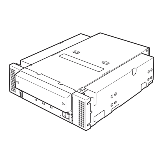
Page 75: Part Name And Function
Part Name and Function The Built-In AIT and magazine have the following parts and functions. Important The part names, functions, and settings of the installed 5.25-in device and installed 3.5-in device (drive only) are the same. (For clarity, we use the 5.25-in device in the explanations below.) Front 1 Dust cover Protects the cartridge slot against... -
Page 76: Rear
Rear 1 Power connector Connect the Built-In AIT’s built-in power cable. (→ P. 81) 2 Jumper pin Pins which set the Built-In AIT (→ P. 77) 3 IDE connector Connect the Built-In AIT’s built-in IDE Flat cable. (→ P. 81) 1 2 3 4 5 6 7 8 1 DIP switch Switches which set the Built-In AIT... -
Page 77: Setup
Setup The procedure up to installation of the Built-In AIT to the “basic processing unit” is explained in the following. Removing and installing the brackets When you want to use the Built-In AIT as a 3.5-in device, you need to remove the left and right brackets. - Page 78 To install the brackets Align the Built-In AIT screw holes with the far end of the bracket adjustable screw holes. With a Phillips screwdriver, tighten the screws. 76 Built-in AIT...
-
Page 79: Setting The Built-In Ait
Setting the Built-In AIT - Setting with the jumper pins - Before installing the Built-In AIT into the 5.25-in. device bay, verify the settings of the Built-In AIT. An ID setting is necessary required to use IDE device integrated with the Built-In AIT. Different IDE devices connected to the same IDE bus, have different IDs so that the devices operate properly. -
Page 80: Setting The Built-In Ait
Setting the Built-In AIT - Setting with the DIP switch - The DIP switch on the bottom of the Built-In AIT enables you to change the following settings. • DC Control (1) (Data compression setting) (Factory-set to ON) • DC Control (2) (Data compression setting) (Factory-set to OFF) 1 2 3 4 5 6 7 8 Switches 1 to 6: Reserved Switch 7: DC Control (1) -
Page 81: Mounting On The Basic Processing Unit
The procedure for installing the drive in a server is as follows. Hint Some servers require the rails to be used. For details on how to install the rails, refer to the server's operating manual. Install the N8151-50A/N8151-53 Built- In AIT under the CD-ROM/RW drive. Important Fig. 1 •... - Page 82 Important When connecting this device to the NEC Express 5800/110Eh, 120Ef or 120Ga, use the IDE cable supplied with the host machine. Otherwise, use the IDE cable supplied with this device. However, if other instructions are provided with the host machine, please follow those instead.
- Page 83 The provided IDE cable is used to CD-ROM/RW drive connect the Built-In AIT, the CD-ROM/ RW drive, and the IDE connector on the motherboard. First, disconnect the cable Built-In AIT between the CD-ROM/RW drive and motherboard and store it in a safe place. Provided cable Connect the provided cable to the IDE connector on the motherboard, then...
-
Page 84: Installing The Tape Device Driver
(Screen shots from the N8151-53 are used to illustrate the steps that follow. If you are using the N8151-50A, places labeled SDX-520V will appear on your screen as SDX-420V.) Click the [Start] button, point to [Settings], click [Control Panel], and then double-click [System]. - Page 85 Click the [Driver] tab, then click the [Update Driver] button. The [Upgrade Device Driver Wizard] appears. Click the [Next] button. The [Install Hardware Device Drivers] screen appears. Select [Search for a suitable driver for my device (recommended)], then click the [Next] button. The [Locate Driver Files] screen appears.
- Page 86 Select the [Floppy disk drives] check box, then click the [Next] button. The basic processing unit starts searching for driver files, then the [Driver Files Search Results] screen appears. Make sure that “a:\win2000\sw2ait.inf” appears in the [Driver Files Search Results] screen, then click the [Next] button.
- Page 87 Make sure that the “Sony AIT 50 GB IDE Drive” appears in the [Device Manager] window. Installation of the tape device driver is now complete. Built-in AIT 85...
- Page 88 For Windows XP Users (Screen shots from the N8151-53 are used to illustrate the steps that follow. If you are using the N8151-50A, places labeled SDX-520V will appear on your screen as SDX-420V.) Click the [Start] button, click [Control Panel], then double-click [System].
- Page 89 Select [Install the software automati- cally (Recommended)], insert the floppy disk provided, then click the [Next] button. The [Please select the best match for your hardware from the list below.] screen appears. Select the hardware associated to “a:\winxp\sxpait.inf”, then click the [Next] button.
- Page 90 Make sure that the “Sony AIT 50 GB IDE Drive” appears in the [Device Manager] window. Installation of the tape device driver is now complete. Hint The device driver that you installed is enabled after you restart the system. 88 Built-in AIT...
- Page 91 (Screen shots from the N8151-53 are used to illustrate the steps that follow. If you are using the N8151-50A, places labeled SDX-520V will appear on your screen as SDX-420V.) Click the [Start] button, point to [Control Panel], then click [System].
- Page 92 Select [Install the software automati- cally (Recommended)], insert the floppy disk provided, then click the [Next] button. The [Please select the best match for your hardware from the list below.] screen appears. Select the hardware associated to “a:\win2003\sxpait.inf”, then click the [Next] button.
- Page 93 Make sure that the “Sony AIT 50 GB IDE Drive” appears in the [Device Manager] window. Installation of the tape device driver is now complete. Built-in AIT 91...
-
Page 94: Handling
Handling The following explains how to handle the Built-In AIT. Setting the AIT data cartridge Important • As the data cartridge to be set in the magazine, use our “AIT Data Cartridge”. If you use a data cartridge of other manufacturer, a read/write error may occur. •... - Page 95 Set the AIT data cartridge orienta- tion as shown here and insert it into the data cartridge slot. By inserting the data cartridge to the extent, it is automatically set in the drive and the TAPE MOTION LED lights. 4 Close the dust cover. Important •...
-
Page 96: Ejecting The Ait Data Cartridge
Ejecting the AIT data cartridge Confirm that the TAPE MOTION LED is not blinking. Pressing the EJECT button, Built-In AIT starts rewinding the tape (this may take a few minutes). When the tape is completely rewound, the data cartridge is automatically ejected from the Built- In AIT. -
Page 97: Led Indication
Remove the data cartridge from the slot and close the dust cover. • When the TAPE MOTION LED is lit or blinking, do not turn off the basic processing unit. This may cause a malfunction or damage data. • To avoid malfunction, do not transport this unit with the data cartridge installed. •... -
Page 98: Cleaning
Cleaning To keep the drive in the good condition, regular cleaning is required. Cleaning the read/write head When the CLEANING REQUEST LED lights, clean the Built-In AIT internal read/write head. Set the provided cleaning cartridge in the drive, following the procedure described in “Handling” in “Setting the AIT Data Cartridge”. -
Page 99: Cleaning The Built-In Ait
Cleaning the Built-In AIT If the Built-In AIT looks dirty, gently wipe its surface with soft cloth moistened with water or detergent. Important Do not clean the Built-In AIT using chemicals such as benzine or thinner (volatile chemicals), which may cause the unit to be deformed or discolored. For the same reason, do not spray insecticide. -
Page 100: Ait Data Cartridge
AIT Data Cartridge This chapter explains how to handle the AIT data cartridge. Data Cartridge Part Name and Function Label paste position Label paste position Handle for insertion/ejection Write-protect plug (The same one is provided on the opposite site.) 98 AIT Data Cartridge... -
Page 101: Operation, Storage And Transportation Requirements
Operation, Storage and Transportation Requirements ■ Operation requirements : 10 to 45 °C Temperature : 20 to 80 % (The maximum temperature of wet bulb is 26 °C.) Humidity Shelf time : If an AIT data cartridge is exposed to an environment other than the operating or storage environment, expose it to the operating environment for a longer time than the period when it is exposed to other environment (for 8 hours at maximum) before use. -
Page 102: Precautions On Entry To Label
Precautions on entry to label • To represent the data contained in the AIT data cartridge, use a label which can be easily replaced and no adhesion trace is left. • To change the label indication, do not erase it with an eraser but peel the old label and paste a new one. -
Page 103: Precautions On Handling
Precautions on Handling Operational precautions Before use • If the AIT data cartridge is damaged, deformed or bent, do not use it. • If the AIT data cartridge is exposed to an environment other than the operating or storage environment, expose it to the operating environment for a longer time than the period when it is exposed to other environment (for 8 hours at maximum) before use. -
Page 104: Usage Inhibition Standard
Usage Inhibition Standard If the AIT data cartridge you are using suffers from one of the conditions below, replace it. • The AIT data cartridge received a strong shock (when falling, for example) and is damaged. Cartridges damaged this way may be broken or warped, their tape covers may no longer open and close properly, which may prevent you from ejecting them from the drive. -
Page 105: Storing Important Data
Storing Important Data When storing important data or programs, it is strongly recommended that you should prepare and store the master tape and copy (backup) tape just in case. Further, we recommend that you verify backup software when saving, and check saved data. For details on verification, refer to the instruction manual for the backup software you are using. -
Page 106: Specifications
Specifications The Built-In AIT has the following specification: ■ Performance Memory capacity • N8151-50A – 35 GB (in compression mode: 70 GB) when using AIT1 Data Cartridge: tape length 230 m – 25 GB (in compression mode: 50 GB) when using AIT1 Data Cartridge: tape length 170 m •... - Page 107 12 V±10% Current (Typ.) 0.9 A 0.3 A Current (Max.) 1.2 A 1.2 A ■ Dimensions, weight N8151-50A/N8151-53 5.25 in device 41.2 mm 149.0 mm 172.2 mm Weight 0.97 kg N8151-50A/N8151-53 3.5 in device 41.2 mm 101.6 mm 172.2 mm Weight 0.74 kg...
-
Page 108: Customer's Application Sheet
Customer’s Application Sheet Use this sheet as a note in which the information required for maintenance and management of the N8151-50A/N8151-53 Built-In AIT. Item Record Basic processing unit model name Operating system (OS) (name, version, service pack/batch application) Backup software (name,... -
Page 109: Troubleshooting Checklist
Troubleshooting Checklist If this product fails to operate as expected, consult the following checklist and verify the product before returning it for repairs. If the device is exhibiting any of the symptoms listed, take the actions indicated. Internal/ Symptom Action External ❑... - Page 110 Internal/ Symptom Action External ❑ The drive is not properly ❑ Make sure that terminators are connected and/or Internal detected during startup. set correctly. External → Terminators must be connected at both ends of the SCSI bus. • If the remote end of the SCSI bus is a cable (connector), make sure that a terminating connector is connected to it.
- Page 111 Internal/ Symptom Action External ❑ The cartridge is not ❑ Clean the head with the cleaning cartridge. Internal ❑ Replace the data cartridge with a new cartridge. detected correctly. External ❑ The backup process is ❑ Make sure that you are using the correct data not performed correctly.
- Page 112 Internal/ Symptom Action External ❑ The backup process is ❑ Refer to the explanation of the LED and LCD Internal not performed correctly. indicators (if any) in the User’s Guide. External → • If a cleaning request is indicated, clean the (An LED is flashing and an error is displayed on drive and attempt the backup process...
- Page 113 Internal/ Symptom Action External ❑ Cannot eject the ❑ If a spent cleaning cartridge is inserted, or if Internal cleaning cartridge. External cleaning is not completed properly because the cartridge ends during cleaning, some drives indicate this by not ejecting the cleaning cartridge.
- Page 116 NEC Corporation 5-7-1 Shiba, Minato-ku, Tokyo Tel. (03) 3454-1111 (Main switchboard) ©2004 NEC Corporation No copying or modifying without permission of NEC Corporation. The contents of this document may be changed without notice. Printed in Japan Printed on recycled paper.
Need help?
Do you have a question about the N8151-50A and is the answer not in the manual?
Questions and answers