
Related Manuals for Enapter Electrolyser 4.1


Summary of Contents for Enapter Electrolyser 4.1
- Page 1 Owner’s Manual Electrolyser 4.1 Please study this manual carefully before unpacking, installing, and operating the device. Rev. 01– October 2023...
- Page 2 VE RS I ON D O CU MEN T TI TLE RELEASE DAT E EL4.1 – Owner’s Manual 2023-10-06 CHANGE HISTORY FOR EL4.1 A black triangle on the left side of the page indicates changes since the last revision. The number inside the triangle indicates the revision which includes the changes the first time.
-
Page 3: Enapter Srl
Thank you for choosing Enapter. Please study this manual carefully before unpacking, installing, and operating the device. If you have any further questions, please contact the Enapter customer support team. Quote the device serial number and hardware number on the back of the device to help identify your product quickly. -
Page 4: Terms
To simplify reading, this document only refers to the operator to distinguish from Enapter but may also include the user, customer, client, owner, installer, instructor, system integrator, or persons who are responsible for safe operation of the device. -
Page 5: Table Of Contents
RE LEAS E DAT E EL4.1 – Owner’s Manual 2023-10-06 TABLE OF CONTENTS Change history for EL4.1 ......................I Enapter Srl ............................. II Scope of the document ........................II Approved use ..........................II Terms ............................III Table of Contents ......................... IV Overview of the Electrolyser .................... - Page 6 Anti-Freezing Routine ....................... 48 Preheat Function ......................48 5.10 Safety Heartbeat ......................48 5.11 Troubleshooting ....................... 49 Enapter Monitoring Tools ..................... 51 Mobile Application ......................51 Maintenance of the Electrolyser..................52 Updates ........................... 52 Routine Maintenance ....................... 52 5-year Major Maintenance ....................54 Cleaning ...........................
-
Page 7: Overview Of The Electrolyser
2023-10-06 1. OVERVIEW OF THE ELECTROLYSER Enapter’s patented anion exchange membrane (AEM) electrolyser is a standardized, stackable, and flexible device to produce hydrogen. The modular, easily maintainable design – paired with advanced software integration – allows set up in minutes and remote control and management. - Page 8 - 802.12 WEP, WPA, WPA2 Personal (Pre-shared key) Communications - Wi-Fi client isolation must be disabled Bluetooth Modbus TCP via Ethernet Enapter Cloud Service, Enapter App, Modbus TCP, Safety chain Remote Control (dry contact) Safety Maximum H contained within 20 NL...
- Page 9 Operating Conditions 5 °C to 45 °C, up to 90% humidity, non-condensing 2 °C to 55 °C, up to 90 % humidity, non-condensing Storage Conditions Contact the Enapter customer support team if storing the device longer than 30 days. IP Rating IP 20 Interfaces Outlet ¼”...
-
Page 10: Front Panel & Bottom
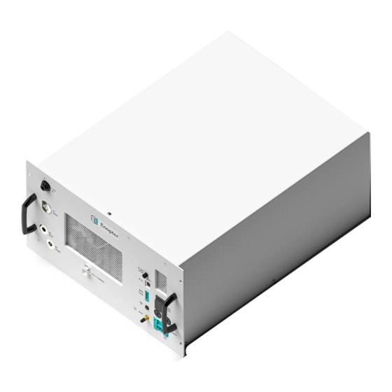
VERS I ON D O CU ME N T TI TLE RE LEAS E DAT E EL4.1 – Owner’s Manual 2023-10-06 1.2 FRONT PANEL & BOTTOM EL4.1 AC air cooled front side EL4.1 DC liquid cooled front side. EL4.1 air cooled bottom view The front panel includes most of the physical connections of the device. - Page 11 The device can be connected to the local network via Bluetooth and Wi-Fi, enabling real-time updates and monitoring for the operator via the Enapter App and cloud. A miniature antenna can be attached to this port to increase the amplification.
-
Page 12: Back Panel
VERS I ON D O CU ME N T TI TLE RE LEAS E DAT E EL4.1 – Owner’s Manual 2023-10-06 Before draining the device through its dedicated port, wear appropriate personal protective equipment (PPE). For more information, refer to Appendix III below. -
Page 13: Safety Instructions
VERS I ON D O CU ME N T TI TLE RE LEAS E DAT E EL4.1 – Owner’s Manual 2023-10-06 2. SAFETY INSTRUCTIONS 2.1 WARNINGS AND HAZARDS The following terms and symbols are used in this manual to indicate important text passages which must be given particular attention: Warns of fatal/serious injuries or death Warns of injury... -
Page 14: General Safety
Caused by improper installation. Regarding design and installation, the operator must follow Enapter’s installation rules, and ensure full compliance with all relevant local safety guidelines, rules, directives, and regulations. The operator must check the device for hydrogen, water, and KOH leakages regularly and ensure that all interfaces are connected correctly. -
Page 15: Additional Safety For The Electrolyser
VERS I ON D O CU ME N T TI TLE RE LEAS E DAT E EL4.1 – Owner’s Manual 2023-10-06 Wear gloves when handling the device. Wear appropriate footwear when handling the device. Use lifting aids if available when lifting the device. Never lift the device alone. Know your local and site-specific health and safety rules and act accordingly. -
Page 16: Hazards
VERS I ON D O CU ME N T TI TLE RE LEAS E DAT E EL4.1 – Owner’s Manual 2023-10-06 3. HAZARDS The operator who operates, services, maintains, or installs this device must be aware of the potential dangers associated with its use and set up, the required materials, as well as the inputs and outputs, to implement sufficient countermeasures and processes to prevent accidents and act correctly in case of emergencies. -
Page 17: Mechanical Hazards
VERS I ON D O CU ME N T TI TLE RE LEAS E DAT E EL4.1 – Owner’s Manual 2023-10-06 3.2 MECHANICAL HAZARDS It is always necessary to wear appropriate personal protective equipment (PPE) and use suitable tools when handling the device and packaging material. Some general training with regards to lifting heavy loads and general safety briefings are required to perform the tasks safely described in this manual. - Page 18 Always turn off the power supply when the device is being cleaned, maintained, or transported. Any servicing, other than cleaning and routine user maintenance, must be performed by trained, Enapter-endorsed technicians. EL4.1 – Owner’s Manual – Rev.01 – October 2023...
-
Page 19: Chemical Hazards
VERS I ON D O CU ME N T TI TLE RE LEAS E DAT E EL4.1 – Owner’s Manual 2023-10-06 3.4 CHEMICAL HAZARDS Potassium Hydroxide is used in the electrolyser as the main process liquid (electrolyte). The electrolyte usually comes pre-mixed with the electrolyser, but it can also be purchased as a powder to be diluted in purified water. -
Page 20: Thermal Hazards
(80 dBA). However, a sudden vent (either caused by device shut down or unforeseen error) can be louder than 85 dB, depending on the vent line installation. Due to this, Enapter recommends wearing PPE (earplugs) while working around the device. -
Page 21: Installation Of The Electrolyser
Please do not dispose of the original shipping materials. Enapter will not accept devices for repair or replacement if they are returned without the original shipping boxes or equivalents for safe transport. - Page 22 VERS I ON D O CU ME N T TI TLE RE LEAS E DAT E EL4.1 – Owner’s Manual 2023-10-06 Stainless-steel pipe cutter (to cut the H Out, H vent, and O vent pipe) ¼” and ⅜” tube bender (to bend the H Out, H vent, and O vent pipe)
-
Page 23: Implementing System Safety
VERS I ON D O CU ME N T TI TLE RE LEAS E DAT E EL4.1 – Owner’s Manual 2023-10-06 4.3 IMPLEMENTING SYSTEM SAFETY Each connection to and from the device must be inspected and tested. Additional system engineering might be required to ensure safe operation. -
Page 24: Process Flow Diagram (Pfd)
The following diagram shows internal components of the device as well as how it interacts with the Enapter Dryer and the Enapter Water Tank. It is also available here. Please note that the diagram is slightly simplified to be more understandable and to protect Enapter’s intellectual property. -
Page 25: Instructions For Connecting Stainless-Steel Pipes
Out port, located at the bottom left of the front panel, to a hydrogen storage tank or the Enapter Dryer. It is recommended to fit a shut-off valve between the tank and the dryer to be able to isolate each component during maintenance. - Page 26 Out port and the storage or other downstream equipment to protect the devices from overpressure. Enapter is not responsible for any damage caused by improperly installed equipment. Please be aware that when larger hydrogen systems are created by putting together several modules, the piping downstream may have to be sized accordingly.
- Page 27 It is the operator’s responsibility to regularly check and maintain all pipes. Please contact the Enapter customer support team for questions regarding the piping. 4.5.2 HYDROGEN VENT CONNECTION GUIDE (H VENT)
- Page 28 The H vent line can be combined with the H purge line of the Enapter DR2.1 using the provided check valve downstream from the electrolyser’s H vent port. Make sure that there is never built-up pressure of more than 0.2 barg inside the pipe and that it is always open to the atmosphere! Otherwise, the device will get permanently damaged.
- Page 29 It is the operator’s responsibility to regularly check and maintain all pipes. Enapter is not responsible for any damage caused to the device from mismanaged piping arrangements. To connect the port labelled “H Vent”, use H...
- Page 30 It is the operator’s responsibility to regularly check and maintain all pipes. Enapter is not responsible for any damage caused to the device from mismanaged piping arrangements. To connect the port labelled “O Vent”, use O...
- Page 31 VERS I ON D O CU ME N T TI TLE RE LEAS E DAT E EL4.1 – Owner’s Manual 2023-10-06 line is sufficient and that it always runs at a downward angle. As water is condensing inside the vent lines, there must not be any horizontal or sagging sections.
- Page 32 VERS I ON D O CU ME N T TI TLE RE LEAS E DAT E EL4.1 – Owner’s Manual 2023-10-06 Three EL4.1 and a DR2.1 with common O2 VENT Details EL4.1 – Owner’s Manual – Rev.01 – October 2023...
- Page 33 VERS I ON D O CU ME N T TI TLE RE LEAS E DAT E EL4.1 – Owner’s Manual 2023-10-06 VENT line and water trap Warning! Risk of explosion! The gaseous outputs from the oxygen vent and the hydrogen vent must be kept separated.
-
Page 34: Instructions For Connecting Plastic Tubes
Ensure water pressure on the input line never exceeds the maximum allowed pressure. This can cause irreparable damage to the device and create significant leakages. Enapter is not responsible for any damage or injury resulting from the misuse of the device. - Page 35 ASTM D1193-06 Type II or Type III. If a device is damaged from using water with insufficient conductivity or debris, Enapter is not responsible for any damage caused. Notice! Insufficient water pressure and interrupted water supply may harm the device! Ensure the water pressure is sufficient.
- Page 36 VERS I ON D O CU ME N T TI TLE RE LEAS E DAT E EL4.1 – Owner’s Manual 2023-10-06 EL4.1 all pipes connected. EL4.1 all pipes connected After performing the first Electrolyte Filling (filling the device with the supplied electrolyte solution), the device will consume water during operation at a rate of around 0.42 l/h.
- Page 37 EL LC COOLING WATER IN and OUT For the cooling of the device, Enapter recommends setting up a closed cooling loop using water or a water glycol mixture as a cooling agent. The cooling agent must be compatible with 1.4301 stainless- steel and POM (Polyoxymethylene), free of particles and be usable at up to 60°C.
- Page 38 VERS I ON D O CU ME N T TI TLE RE LEAS E DAT E EL4.1 – Owner’s Manual 2023-10-06 It is recommended to set up the cooling loop according to the schematic on the left. The return line (from the “COOLING OUT”...
- Page 39 VERS I ON D O CU ME N T TI TLE RE LEAS E DAT E EL4.1 – Owner’s Manual 2023-10-06 Possible cooling agent temperatures depending on the flow rate and ambient temperature. The x-axis shows the environmental temperature, while the y-axis shows the coolant temperature. The graph differentiates between the following three sections: the top red one represents the possible working conditions if the coolant flow rate is at the maximum allowed 2 L/min;...
- Page 40 Ensure that the cooling agent pressure on the input line never exceeds 4 barg. Make sure that the cooling agent is filtered and free of particles. This can cause irreparable damage to the device and create significant leakages. Enapter is not responsible for any damage or injury resulting from the misuse of Enapter products.
- Page 41 VERS I ON D O CU ME N T TI TLE RE LEAS E DAT E EL4.1 – Owner’s Manual 2023-10-06 Three EL4.1 and a DR2.1 with common Cooling pipes Details EL4.1 – Owner’s Manual – Rev.01 – October 2023...
-
Page 42: Electrical Connection Guide (Power)
Enapter recommends installing a protective device against overload and short circuits for all device versions on the power supply line. It must be selected in relation to the device’s maximum power consumption and in compliance with all local and national safety requirements. To further increase electrical safety of the device, it is recommended to install an SPD (Surge Protection Device) to protect EL4.1 –... - Page 43 VERS I ON D O CU ME N T TI TLE RE LEAS E DAT E EL4.1 – Owner’s Manual 2023-10-06 the device from potential over-voltages generated by lightning strikes, as well as an appropriately sized differential breaker for the installation. 4.7.1 AC VERSION Connect the device to the socket labelled “Power”.
-
Page 44: Dry Contact Connection Guide (Optional) (Dry Con.)
VERS I ON D O CU ME N T TI TLE RE LEAS E DAT E EL4.1 – Owner’s Manual 2023-10-06 4.7.2 DC VERSION The DC version has a 2-pins connector compatible with cross section cables of 16mm². The upper one is the positive voltage input (usually red cable). - Page 45 The pins are, from top to bottom, S2, COM2, S1, COM1. This allows the device to not only receive a dry contact signal but also to pass it on to the next Enapter device. The operator can daisy chain as many Enapter devices as wanted to a common loop.
- Page 46 VERS I ON D O CU ME N T TI TLE RE LEAS E DAT E EL4.1 – Owner’s Manual 2023-10-06 Dry Con daisy chain with two electrolysers and Emergency Details Switch EL4.1 – Owner’s Manual – Rev.01 – October 2023...
-
Page 47: Ethernet Port (Eth.)
Bluetooth must be used. Please find more information in the chapter Pairing the device to the cloud. The Modbus command interface table can be accessed online via Enapter handbook. The Ethernet cable must be shielded. EL4.1 – Owner’s Manual – Rev.01 – October 2023... -
Page 48: Iso 22734 Requirements
To create an account, click on the create account button on the first screen. After logging in on the Enapter app, create a site – a virtual environment which will show all the telemetries collected from the devices connected to the cloud via UCMs (Universal Communication Modules). - Page 49 4.11.3 ELECTROLYTE FILLING When the device is connected to a water supply and to the Web GUI or Enapter app, it is now ready to be commissioned for its first use. Once it is successfully paired to the cloud, it starts in maintenance mode and gives prompts to perform the first-time filling.
- Page 50 Push CPC connector in to connect Filling instructions: Make sure that the device is online to follow the Enapter App or use the Web GUI instructions to fill the device. Put on PPE. The minimum required equipment are safety goggles to protect from splashes and nitrile gloves.
- Page 51 VERS I ON D O CU ME N T TI TLE RE LEAS E DAT E EL4.1 – Owner’s Manual 2023-10-06 port when filling up electrolyte. If there is no water supply source available yet, the device will show a warning that no water supply source is attached. However, it is still possible to produce hydrogen for a few hours until the automatic refilling is triggered.
-
Page 52: Operation Of The Electrolyser
This helps to ensure the longevity of the device. 5.2 REMOTE START/STOP The device can be started/stopped remotely using the Enapter app or cloud as well as remotely via the Modbus interface. For more information on this, please refer to the online Enapter handbook. -
Page 53: Maintenance Mode
2023-10-06 5.4 MAINTENANCE MODE Maintenance mode can be manually enabled using the Enapter App. It is used to safely fill and drain the device, as well as to guide through inspection and other routine maintenance tasks. Please see the chapter Routine Maintenance to know more. -
Page 54: Ramp Down
VERS I ON D O CU ME N T TI TLE RE LEAS E DAT E EL4.1 – Owner’s Manual 2023-10-06 Warm-up time (time taken for the electrolyte to heat up to 55 °C): The electrolyser can reach a heating ratio of 1 °C/min. If starting the device with an electrolyte temperature of e.g., 25 °C it will take about 30 min to be fully operational and perform at its maximum efficiency at 55 °C. -
Page 55: Troubleshooting
Preparing fresh electrolyte). It’s the operator’s responsibility to ensure that only water with very low conductivity is supplied to the device. Enapter recommends that the conductivity shall always be below 5µS/cm. In case of a water leakage, please follow the instructions below to drain the water from the device. - Page 56 VERS I ON D O CU ME N T TI TLE RE LEAS E DAT E EL4.1 – Owner’s Manual 2023-10-06 The hole at the bottom of the device allows water and electrolyte inside the device to drain. To drain accumulated fluids, prepare a KOH resistant bucket of 3 L. Put on personal protective equipment.
-
Page 57: Enapter Monitoring Tools
The device comes with a preinstalled UCM (Universal Communication Module) to monitor and manage the device. Various sensor data from the devices is stored in the Enapter Cloud in a time-series database and provides real-time or on-demand visualization of collected data on customizable dashboards. To support the latest protocols and security fixes, the UCM can be updated over-the-air. -
Page 58: Maintenance Of The Electrolyser
Testing. Additionally, the Proof-tests described in the Safety Manual must be executed successfully once per year. For more information, please look at the Safety Manual or contact the Enapter customer support team. After commissioning, the process tank must be emptied at least once a year and new electrolyte filled into the device. - Page 59 When the device has been drained during maintenance, it might request a flushing process via the Enapter App. Keep the device in maintenance mode while observing it in the Enapter App or the WebGUI. The flushing process will use purified water from the H O In port to flush the internal tank.
-
Page 60: 5-Year Major Maintenance
To ensure that the safety system works properly, the device needs to be inspected by Enapter or one of its authorized service partners every five years (mission time) for major maintenance. More details can be found in the Safety Manual. -
Page 61: Disposal
7.5 DISPOSAL Enapter is fully committed to recycling the devices and their components. Please return the device to Enapter at the end of life, when the device will be fully recycled. By ensuring this product is correctly recycled, you will help to further reduce your impact on the environment and aid us in making the world cleaner and greener. - Page 62 VERS I ON D O CU ME N T TI TLE RE LEAS E DAT E EL4.1 – Owner’s Manual 2023-10-06 Notice! Do not exceed the allowed temperatures! During winter, or when outside conditions are below freezing temperature as well as for very hot environments, the shipping box must be additionally marked with a label informing the shipping agent that the package may not be exposed to temperatures outside of the given storage temperatures stated in the datasheet.
-
Page 63: Appendix
VERS I ON D O CU ME N T TI TLE RE LEAS E DAT E EL4.1 – Owner’s Manual 2023-10-06 8. APPENDIX Appendix I. Hydrogen Leak Testing As part of a hydrogen device, it is of vital importance to check every connection made for leaks. For more information on this matter, please refer to the appendix of ASME B31.12. -
Page 64: Appendix Ii. Preparing Fresh Electrolyte
Ensure all material used to store and contain the electrolyte solution is chemically compatible with its contents. We recommend contacting Enapter to make sure that the purchased product is compatible (support@enapter.com) EL4.1 – Owner’s Manual – Rev.01 – October 2023... -
Page 65: Appendix Iii. Draining The Electrolyte
The module must be drained for transport, installation, and before the routine changing of the electrolyte in the device to prolong its lifetime. To do this, the device must be first switched into Maintenance Mode using Enapter mobile app or cloud. Follow the steps outlined in the app or use the instructions below. - Page 66 Notice! Chemicals might damage the device! Carefully read the instructions below before starting. Follow the instructions carefully and contact the Enapter customer support team in case of questions. Ensure all material used to store and contain the electrolyte solution is chemically compatible with its contents.
-
Page 67: Appendix Iv. Led States
VERS I ON D O CU ME N T TI TLE RE LEAS E DAT E EL4.1 – Owner’s Manual 2023-10-06 Appendix IV. LED States EL4.1 AC version LEDs DR2.1 LEDs The three LEDs on the front panel help to indicate the device status and operating condition. During normal operation, the LEDs indicate the status of the device.
Need help?
Do you have a question about the Electrolyser 4.1 and is the answer not in the manual?
Questions and answers