
Subscribe to Our Youtube Channel
Related Manuals for Enapter EL 2.1


Summary of Contents for Enapter EL 2.1
- Page 1 Narrow Body EL 2.1 (Rev. A) Hydrogen Generator (35bar) Owner’s Manual Rev. 02 – March 2021...
-
Page 2: Preface
If you have any further questions on the installation of the device, please contact the Enapter support team. Quote the system serial number when contacting us; you can find the serial number on the modules' back. -
Page 3: Table Of Contents
Safety Heartbeat ____________________________________________________________________ 35 Transport, Maintenance and Recycling _________________________________________ 36 The EL 2.1 Hydrogen Generator is designed to provide many hours of service with minimal maintenance. Proper care and maintenance by qualified personnel help maximize the operating life of the unit. The device was designed for easy maintenance and to be a repairable device. - Page 4 Appendix II. Preparing the electrolyte solution ______________________________________________ 39 Appendix III. Draining the EL2.1 ___________________________________________________________ 41 Appendix IV. Integration in Cabinets _______________________________________________________ 42 Appendix V. LED States _________________________________________________________________ 43 Appendix VI. Error Codes ________________________________________________________________ 43 EL 2.1 - Owner’s Manual - Rev.02 – Mar 2021...
-
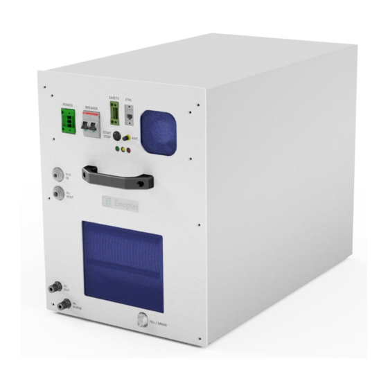
Page 5: Product Overview
RODUCT VERVIEW Enapter's patented anion exchange membrane (AEM) electrolyser is a standardised, stackable and flexible system to produce on-site hydrogen. The modular, easily maintainable design – paired with advanced software integration – allows set up in minutes and remote control and management. To achieve the required hydrogen production capacity, simply stack this on any housing you wish. - Page 6 10) ANT. – Antenna port This is where a miniature antenna is attached to connect the device to the local network via Bluetooth and Wi-Fi, enabling real-time updates and monitoring for the user via the Enapter App and cloud. Do not touch the antenna when the device is powered on!
-
Page 7: Technical Specifications
Outlet 1/4“ Swagelok Tube Fitting Vent Outlet 10 mm Speed fit Purge Outlet 1/4“ Swagelok Tube Fitting Water Inlet 8 mm Speed fit Fill and Drain Port CPC quick connector 10 mm EL 2.1 - Owner’s Manual - Rev.02 – Mar 2021... -
Page 8: Safety Instructions
Caused by improper installation of the machine 3. With regards to the design and installation of the hydrogen outlet, purge and vent lines, the customer must follow Enapter's installation guide, but also ensure full compliance with local safety guidelines and regulations. - Page 9 17. Do not store the unit at temperatures below 1°C. If this occurs, a freezing check sticker placed on the EL 2.1 Electrolyte bag box will become RED. In this case, please contact Enapter support team before commissioning the device.
-
Page 10: List Of Hazards
Whilst the handling of the packaging material and preliminary installation does not require specialised technicians, a general training with regards to lifting heavy loads and general safety briefings are required to perform these tasks safely. EL 2.1 - Owner’s Manual - Rev.02 – Mar 2021... - Page 11 Always turn off the power supply when the product is being cleaned, maintained or transported. Any servicing, other than cleaning and routine user maintenance, must be performed by trained, Enapter-endorsed technicians. EL 2.1 - Owner’s Manual - Rev.02 – Mar 2021...
- Page 12 Collect the liquid in an appropriate container and place in a chemical waste container. Do not flush to sewer. Dispose of the liquid in compliance with applicable local regulations. EL 2.1 - Owner’s Manual - Rev.02 – Mar 2021...
- Page 13 Remove the supply of power before any service, transport and installation of the device. • Never open the device, unless you have been specially trained for service by Enapter. • Any servicing, other than cleaning and user maintenance must be performed by specialist personnel and with the power supply switched off.
-
Page 14: Installation
Electrolyte filling bag (labelled) • Safety chain jumpers • Ferrite for power input cable • Swagelok Nut and Ferrule set • 10mm Check Valve **only needed when connecting multiple Electrolysers** EL 2.1 - Owner’s Manual - Rev.02 – Mar 2021... -
Page 15: Unpacking
"Transport, Maintenance and Recycling". Warning! Never lift the EL2.1 out of the packaging alone. An EL 2.1 weighs over 50 kg. Use lifting aids if available. Due to their weight and size, it is recommended to use a pallet cart or similar devices to manoeuvre the box upon delivery. -
Page 16: El2.1 Connection Guide
Do not install, operate or maintain the system without explicit knowledge or help from experienced and licensed system integrators, the manufacturer or external certifying bodies. If any further questions should arise, please contact the appropriate Enapter service and support teams who will answer any questions about the installation and integration of the Electrolyser. - Page 17 3. To disconnect, ensure the line is depressurised. Then push the collet against the fitting, while simultaneously pushing the tube into the fitting. Holding the collet in this position pull the tube out of the fitting in one smooth motion. EL 2.1 - Owner’s Manual - Rev.02 – Mar 2021...
- Page 18 3. To disconnect, push the collet against the fitting, while simultaneously pushing the tube into the fitting. Holding the collet in this position pull the tube out of the fitting in one smooth motion. EL 2.1 - Owner’s Manual - Rev.02 – Mar 2021...
-
Page 19: Hydrogen Outlet Connection Guide
All pressurised connections must be inspected and checked for leakages. Failure to do so significantly increases the risk of explosion. Enapter is not responsible for any damage caused by improperly installed equipment. Several units of EL2.1s can be safely connected together. -
Page 20: Purge Connection Guide
1-10 ml of water (mostly liquid) is released with the gas. Attention! It is not the responsibility of Enapter S.r.l. to install and ensure the purge line is appropriately managed and maintained. Carefully refer to local rules and regulations, apply industrial safety standards where possible and assess the... - Page 21 The customer/system integrator must ensure that the purge outlet satisfies all relevant local rules and regulation, in terms of noise emission, risk assessments, maintenance and all other relevant areas. EL 2.1 - Owner’s Manual - Rev.02 – Mar 2021...
-
Page 22: Vent Connection Guide
– however, permanent damage to the system can occur from overpressures. Enapter is not responsible for any damage caused to the system from mismanaged vent line arrangements. To connect a device, create a connection using 10 mm LDPE pipe to the port labelled "O Vent". - Page 23 It is then possible to fully separate the outputs – the oxygen gas mixture can be led to a safe area, while the water can be safely drained. EL 2.1 - Owner’s Manual - Rev.02 – Mar 2021...
-
Page 24: Water Inlet Connection Guide
In order to supply the EL2.1 with clean DI water for refilling, water must be present in the electrolyser water refilling pipe at a pressure between 0.5 bar and 4 bar. If the EL 2.1 does not detect the water's pressure, the system will not refill and will stop operation while it waits for water input pressure to appear. - Page 25 To facilitate faster refills, it is recommended to have at most 9 (nine) devices supplied by the same water line when connected only to Enapter's Water Tank Module. EL 2.1 - Owner’s Manual - Rev.02 – Mar 2021...
-
Page 26: Electrical Connection Guide
13.77 mm (350 Ohm, 150 MHz) and can simply be slid over the cable. Connect the EL 2.1 as shown below to the socket labelled "Power". In the image below, brown is live, blue is neutral, and the yellow/green is the ground. Follow the relevant safety standards and ensure compliance with local and national regulations using the male connector in the correct orientation, as shown below.. - Page 27 The EL 2.1 must be connected to ground to prevent users from contact with dangerous voltage and to allow the correct functioning of the device. The grounding system must comply with local and national regulations.
- Page 28 The pins are, from top to bottom, S2, COM2, S1, COM1. This allows the EL to not only receive a dry contact signal but also to pass it on to the next Enapter device, allowing the installer/operator to daisy chain as many Enapter devices as wanted to a common safety signal.
-
Page 29: Electrolyser Monitoring Tools
The EL 2.1 comes with a preinstalled UCM (Universal Communication Module), which provides the immediate ability to monitor and manage the device. It does this by sending data to the Enapter Cloud, which stores it in a time-series database and provides real-time or on-demand visualisation of collected data on customisable dashboards. -
Page 30: Commissioning Of The El2.1
If you have any questions relating to the safety and installation of the EL2.1, please refer to the Enapter handbook, or contact Enapter support online via the cloud, or by email or telephone. EL 2.1 - Owner’s Manual - Rev.02 – Mar 2021... -
Page 31: Safety Areas Around The Purge And Vent Outlet
API 521: Pressure-relieving and Depressuring Systems Or follow the recommendations of Enapter for systems up to ten EL2.1s and 2 DR2.1s. The safety area is cylindrical and has a height of 10 meters and a radius of 5 meters. Note that depending on the design of the purge piping and exit velocity, this area also extends in the direction of the ground by at least 1 meter. -
Page 32: Preparing For H2 Production
To create an account, click on the create account button of the first screen. Step 2) After logging in on the Enapter app, create a site – a virtual environment which will house all of the telemetries collected from the devices in your system connected to the cloud via UCMs (Universal Communication Modules). - Page 33 The device is ready to be used. If you have any questions relating to the safety, installation and control of the EL2.1, please refer to the Enapter handbook or contact Enapter support online via the cloud, or by email or telephone. EL 2.1 - Owner’s Manual - Rev.02 – Mar 2021...
-
Page 34: Control, Functions And System States
Remote Start/Stop The EL can be started remotely using the Enapter app or cloud, by any user with access and correct permissions to the site the device was added to. For detailed information on this, please refer to the mobile application handbook. -
Page 35: Ramp Up
25 °C, then the warm-up time is 30, so you need 5 min to build pressure). During ramp up, the system performs periodical purges to guarantee high purity H2 on the outlet, as well as to release condensed water from the produced H2. EL 2.1 - Owner’s Manual - Rev.02 – Mar 2021... -
Page 36: Blowdown Routine
The Safety Heartbeat functionality is a periodic signal that is generated by the Gateway and sent to the EL 2.1, in order to verify Electrolyser connection with the Mobile App or Enapter Cloud. If the Electrolyser does not receive this signal from the gateway within a specified time period, it will undergo a normal shutdown. -
Page 37: Transport, Maintenance And Recycling
AINTENANCE AND ECYCLING The EL 2.1 Hydrogen Generator is designed to provide many hours of service with minimal maintenance. Proper care and maintenance by qualified personnel help maximize the operating life of the unit. The device was designed for easy maintenance and to be a repairable device. The modular design principle and repairability allow the hydrogen generator systems to be utilised in a large variety of applications, as well as in off-grid installation with a high degree of confidence. -
Page 38: Disposal
Disposal Enapter is fully committed to recycling the EL 2.1 and its components. Please return the device to Enapter at the end of life, where we will fully recycle the system. By ensuring this product is correctly recycled, you will help to further reduce your impact on the environment and aid us in making the world cleaner and greener. -
Page 39: Appendix
Cons • • Useful for final verification during Cannot detect exact leakage source • system commissioning Cannot grade leakage rates accurately • Can verify several connections at the same time EL 2.1 - Owner’s Manual - Rev.02 – Mar 2021... -
Page 40: Appendix Ii. Preparing The Electrolyte Solution
4, perform another visual check to see if any other debris may be visible. Step 4) Fill 3.6L of DI water with a conductivity below 20 µS/cm at 25⁰C into the KOH resistant container. EL 2.1 - Owner’s Manual - Rev.02 – Mar 2021... - Page 41 Fill the KOH into the container with the DI water. The KOH reaction with water will produce a lot of heat until the pellets are fully dissolved! Immediately stir the solution or mix it around the container with the lid firmly closed. EL 2.1 - Owner’s Manual - Rev.02 – Mar 2021...
-
Page 42: Appendix Iii. Draining The El2.1
Do not flush to sewer. Dispose of the liquid in compliance with local and national regulations. Step 7) Once water stops pouring, safely remove the drain connector. To disconnect, push the button and pull the connector out of the bulkhead. EL 2.1 - Owner’s Manual - Rev.02 – Mar 2021... -
Page 43: Appendix Iv. Integration In Cabinets
2021-03-22 Appendix IV. Integration in Cabinets Please, contact Enapter support for help when starting a new integration project for the narrow body EL2.1. It is the responsibility of the integrator to ensure that all devices contained in the cabinet are kept within operating limits. -
Page 44: Appendix V. Led States
When there is a malfunctioning, the LEDs also indicate the Severity Levels. Please, see the Handbook Appendix VI. Error Codes For detailed information on all the errors that can be triggered, please see the Enapter handbook EL 2.1 - Owner’s Manual - Rev.02 – Mar 2021...
Need help?
Do you have a question about the EL 2.1 and is the answer not in the manual?
Questions and answers