
Related Manuals for Enapter Electrolyser 4.0


Summary of Contents for Enapter Electrolyser 4.0
- Page 1 Owner’s Manual Electrolyser 4.0 Please study this manual carefully before unpacking, installing, and operating the device. Rev. 00 – September 2022...
-
Page 2: Preface
Thank you for choosing Enapter. Please study this manual carefully before unpacking, installing, and operating the device. If you have any further questions, please contact the Enapter customer support team. Quote the device serial number and hardware number on the back of the device to help identifying your product quickly. -
Page 3: Terms
To simplify reading, this document only refers to the operator to distinguish from Enapter but may also include the user, customer, client, owner, installer, instructor, system integrator or persons who are responsible for a safe operation of the device. -
Page 4: Table Of Contents
RELEAS E DAT E EL 4.0 – Owner’s Manual 2022-09-12 TABLE OF CONTENTS Preface ........................... I Enapter Srl ............................I Scope of the document ........................I Approved use ..........................I Terms II Table of Contents ......................... III 1.Overview of the Electrolyser ....................1 Specifications ........................ - Page 5 Blowdown Routine ......................44 Anti-Freezing Routine ....................... 44 Safety Heartbeat ......................44 5.10 Troubleshooting ....................... 44 6.Enapter Monitoring Tools ....................46 Mobile Application ......................46 7.Maintenance of the Electrolyser ..................47 Updates ........................... 47 Routine Maintenance ....................... 47 Cleaning ........................... 48 Disposal ...........................
-
Page 6: Overview Of The Electrolyser
2022-09-12 1. OVERVIEW OF THE ELECTROLYSER Enapter’s patented anion exchange membrane (AEM) electrolyser is a standardised, stackable, and flexible device to produce hydrogen. The modular, easily maintainable design – paired with advanced software integration – allows set up in minutes and remote control and management. - Page 7 - 802.12 WEP, WPA, WPA2 Personal (Pre-shared key) Communications - Wi-Fi client isolation must be disabled Bluetooth Modbus TCP via Ethernet Enapter Cloud Service, Enapter App, Modbus TCP, Safety chain Remote Control (dry contact) Safety Maximum H contained within 20 NL Machinery Directive and relevant harmonised standards: 2006/42/CE;...
- Page 8 VE RS I ON D O CU MEN T TI TLE RELEAS E DAT E EL 4.0 – Owner’s Manual 2022-09-12 Restriction of hazardous substances directive RoHS II 2011/65/EU, delegate directive UE 2015/863 and directive 2017/2102 Noise level at 1 m <85 dB To be installed in a safe (non hazardous) area only.
-
Page 9: Front Panel & Bottom
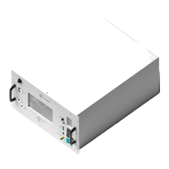
VE RS I ON D O CU MEN T TI TLE RELEAS E DAT E EL 4.0 – Owner’s Manual 2022-09-12 1.2 FRONT PANEL & BOTTOM EL4.0 AC air cooled front side EL4.0 DC liquid cooled front side EL4.0 air cooled bottom view The front panel includes most of the physical connections of the device. - Page 10 The device can be connected to the local network via Bluetooth and Wi-Fi, enabling real-time updates and monitoring for the operator via the Enapter App and cloud. A miniature antenna can be attached to this port to increase the amplification.
- Page 11 VE RS I ON D O CU MEN T TI TLE RELEAS E DAT E EL 4.0 – Owner’s Manual 2022-09-12 Air Inlets – please refer to the Routine Maintenance Keep the air inlets free from dust and dirt LEDs –...
-
Page 12: Back Panel
VE RS I ON D O CU MEN T TI TLE RELEAS E DAT E EL 4.0 – Owner’s Manual 2022-09-12 1.3 BACK PANEL EL4.0 air cooled back side EL4.0 liquid cooled back side The back panel of the device is used to blow out warm air. The stickers show the device specifications and serial number details. -
Page 13: Safety Instructions
VE RS I ON D O CU MEN T TI TLE RELEAS E DAT E EL 4.0 – Owner’s Manual 2022-09-12 2. SAFETY INSTRUCTIONS 2.1 WARNINGS AND HAZARDS The following terms and symbols are used in this manual to indicate important text passages which must be given particular attention: Warns of fatal/serious injuries or death Warns of injury... -
Page 14: General Safety
Caused by improper installation Regarding design and installation, the operator must follow Enapter’s installation rules, and ensure full compliance with all relevant local safety guidelines, rules, directives and regulations. The operator must check the device for hydrogen, water and KOH leakages regularly and ensure that all interfaces are connected correctly. - Page 15 VE RS I ON D O CU MEN T TI TLE RELEAS E DAT E EL 4.0 – Owner’s Manual 2022-09-12 Wear appropriate footwear when handling the device. Use lifting aids if available when lifting the device. Never lift the device alone. Know your local and site-specific health and safety rules and act accordingly.
-
Page 16: Additional Safety For The Electrolyser
VE RS I ON D O CU MEN T TI TLE RELEAS E DAT E EL 4.0 – Owner’s Manual 2022-09-12 2.3 ADDITIONAL SAFETY FOR THE ELECTROLYSER This device contains a SIL1 Safety Instrumented System (SIS) within, managing inner safety instrumented functions (SIF). -
Page 17: Hazards
VE RS I ON D O CU MEN T TI TLE RELEAS E DAT E EL 4.0 – Owner’s Manual 2022-09-12 3. HAZARDS The operator who operates, services, maintains, or installs this device must be aware of the potential dangers associated with its use and set up, the required materials, as well as the inputs and outputs, to implement sufficient countermeasures and processes to prevent accidents and act correctly in case of emergencies. -
Page 18: Electrical Hazards
VE RS I ON D O CU MEN T TI TLE RELEAS E DAT E EL 4.0 – Owner’s Manual 2022-09-12 A general training with regards to lifting heavy loads and general safety briefings are required to perform the tasks safely described in this manual. Operators must comply with the general safety principles during the handling phases. -
Page 19: Chemical Hazards
Always turn off the power supply when the device is being cleaned, maintained, or transported. Any servicing, other than cleaning and routine user maintenance, must be performed by trained, Enapter-endorsed technicians. 3.4 CHEMICAL HAZARDS Potassium Hydroxyde is used in the electrolyser as the main process liquid (electrolyte). The electrolyte usually comes pre-mixed with the electrolyser but it can also be purchased as a powder to be diluted in purified water. -
Page 20: Chemical Information
VE RS I ON D O CU MEN T TI TLE RELEAS E DAT E EL 4.0 – Owner’s Manual 2022-09-12 3.5 CHEMICAL INFORMATION Substance: Potassium Hydroxide CAS no.: 1310-58-3 EC no.: 215-181-3 Classification: C. R Phrases: R22, R36/38, R43, R42 S Phrases: S24-37, S39, S62 (see Safety Material Data Sheet included in the shipment) EL –... -
Page 21: Thermal Hazards
(80 dBA). However, a sudden vent (either caused by device shut down or unforeseen error) can be louder than 85 dB, depending on the vent line installation. Due to this, Enapter recommends wearing PPE (earplugs) while working around the device. -
Page 22: Installation Of The Electrolyser
Please do not dispose the original shipping materials. Enapter will not accept devices for repair or replacement if they are returned without the original shipping boxes or equivalents for a safe transport. - Page 23 VE RS I ON D O CU MEN T TI TLE RELEAS E DAT E EL 4.0 – Owner’s Manual 2022-09-12 4.2.2 MATERIAL It’s the operator’s responsibility to chose the correct material according to the individual setup and all relevant local safety guidelines, rules, directives and regulations. ...
-
Page 24: Implementing System Safety
ISO/TR 15916:2015: Basic considerations for the safety of hydrogen systems 2. Or follows the recommendations of Enapter for systems consisting of up to ten electrolysers and two dryers. The safety area is cylindrical and has a height of 10 meters and a radius of 5 meters. -
Page 25: Piping And Instrumentation Diagram (P&Id)
The following diagram shows internal components of the device as well as how it interacts with the Enapter Dryer and the Enapter Water Tank. It is also available here. Please note that the diagram is slightly simplified to be better understandable and to protect Enapter’s intellectual property. - Page 26 Out port, located at the bottom left of the front panel, to a hydrogen storage or the Enapter Dryer. It is recommended to fit a shut-off valve between the tank and the dryer to be able to isolate each component during maintenance.
- Page 27 Make sure to install a pressure relief device between the device’s H2 Out port and the H2 storage or other downstream equipment to protect the devices from overpressure. Enapter is not responsible for any damage caused by improperly installed equipment. Please be aware that when larger hydrogen systems are created by putting together several modules, the piping downstream may have to be sized accordingly.
- Page 28 VE RS I ON D O CU MEN T TI TLE RELEAS E DAT E EL 4.0 – Owner’s Manual 2022-09-12 4.5.2 HYDROGEN VENT CONNECTION GUIDE (H VENT) Connect the H vent port, located at the bottom left of the front panel, to your hydrogen vent outlet.
-
Page 29: Instructions For Connecting Plastic Tubes
Caution! Never mix the output of the H2 vent line with the output of the O2 vent line. The H2 vent line can be combined with the H2 purge line of the Enapter DR2.1, using the check valves downstream the electrolyser H2 vent ports. - Page 30 It is the operator’s responsibility to regularly check and maintain all pipes. Enapter is not responsible for any damage caused to the device from mismanaged piping arrangements. To connect the port labelled “O Vent”, use heat and KOH resistant pipes, sealings and connectors only.
- Page 31 VE RS I ON D O CU MEN T TI TLE RELEAS E DAT E EL 4.0 – Owner’s Manual 2022-09-12 and that it always runs declining. As water is condensing inside the vent lines, there must not be any horizontal or sagging sections.
- Page 32 Ensure water pressure on the input line never exceeds the maximum allowed pressure. This can cause irreparable damage to the device and create significant leakages. Enapter is not responsible for any damage or injury resulting from the misuse of the device.
- Page 33 VE RS I ON D O CU MEN T TI TLE RELEAS E DAT E EL 4.0 – Owner’s Manual 2022-09-12 EL4.0 all pipes connected EL4.0 all pipes connected After performing the first-time filling (filling the device with the supplied electrolyte solution), the device will consume water during operation, at a rate of around 0.42 l/h.
- Page 34 EL LC COOLING WATER IN and OUT For the cooling of the device, Enapter recommends setting up a closed, non-pressurised cooling loop using water or a water glycol mixture as cooling agent. At an external heat exchanger, the waste heat can either be transferred to another medium for further use or be dissipated to the ambient by a fan.
- Page 35 1.4301 stainless steel and LLDPE, free of particles and be usable at up to 60°C. Depending on the ambient temperature, a frost protection agent may need to be added. To further increase device reliability, install the filter supplied by Enapter on the cooling line inlet of the device. EL LC...
- Page 36 VE RS I ON D O CU MEN T TI TLE RELEAS E DAT E EL 4.0 – Owner’s Manual 2022-09-12 The external heat exchanger must be sized to be able to transfer up to 1000 W out of each electrolyser connected to the cooling loop.
- Page 37 Ensure that the cooling agent pressure on the input line never exceeds 7 barg. Make sure that the cooling agent is filtered and free of particles. This can cause irreparable damage to the device and create significant leakages. Enapter is not responsible for any damage or injury resulting from the misuse of Enapter products.
-
Page 38: Electrical Connection Guide (Power)
Do not exceed the specified voltage and amperage (see datasheet for more details). Enapter recommends installing a protective device against overload and short circuits for all device versions on the power supply line. It must be selected in relation to the devices maximum power consumption and in compliance with all local and national safety requirements. -
Page 39: Dry Contact Connection Guide (Optional) (Dry Con.)
VE RS I ON D O CU MEN T TI TLE RELEAS E DAT E EL 4.0 – Owner’s Manual 2022-09-12 In case the fuses blow, open the slots on the front panel to replace them. The fuses to be used are the following: Two fuses each with 250 V, 12.5 A (T), Ø5 x 20mm. - Page 40 The pins are, from top to bottom, S2, COM2, S1, COM1. This allows the device to not only receive a dry contact signal but also to pass it on to the next Enapter device. The operator can daisy chain as many Enapter devices as wanted to a common loop.
- Page 41 VE RS I ON D O CU MEN T TI TLE RELEAS E DAT E EL 4.0 – Owner’s Manual 2022-09-12 Dry Con daisy chain with two electrolysers and Emergency Switch EL – Owner’s Manual – Rev.00 – September 2022...
- Page 42 VE RS I ON D O CU MEN T TI TLE RELEAS E DAT E EL 4.0 – Owner’s Manual 2022-09-12 4.8.1 DRY CONTACT CONNECTION BYPASS To disable the dry con chain functionality, insert the dry con jumper with the red connection cable in the lower part of the socket labelled with “DRY CON”...
-
Page 43: Ethernet Port (Eth.)
ISO 22734 REQUIREMENTS The device is ISO 22734 ready. To reach the full conformity to ISO 22734 it is the operator’s responsibility to additionally fulfil the following requirements from ISO 22734 which cannot be covered by Enapter. ISO 22734 Title... - Page 44 It is time to power on the device for the first time. Switch the breaker at the top of the front panel in the upper position to switch the device on. Use the Enapter app to add the device to a site. For detailed information on this, please refer to the mobile application handbook.
- Page 45 The mode can be checked by looking at the status of LSL102D_in (Low electrolyte level) in the Cloud: it is “false“ (red) if the tank is empty. If not – please contact the Enapter customer support team. Do not leave the device powered on and unattended while in Maintenance mode.
- Page 46 VE RS I ON D O CU MEN T TI TLE RELEAS E DAT E EL 4.0 – Owner’s Manual 2022-09-12 You are done! The device is ready to be used and no other action is required. The electrolyser will automatically refill demineralised water via the H O In port whenever it needs it.
-
Page 47: Operation Of The Electrolyser
This helps to ensure the longevity of the device. 5.2 REMOTE START/STOP The device can be started/stopped remotely using the Enapter app or cloud as well as remotely via the Modbus interface. For more information on this, please refer to the online Enapter handbook. -
Page 48: Ramp Up
VE RS I ON D O CU MEN T TI TLE RELEAS E DAT E EL 4.0 – Owner’s Manual 2022-09-12 Enter a number between 60 and 100 to set the production rate to a desired percentage (60 % - 100 %). Then click on the button "Create Command". -
Page 49: Blowdown Routine
The device will automatically stop the operation in case of a fatal error. For further troubleshooting please visit handbook.enapter.com. In case of a water leakage please follow the instructions below to drain the water from the device. - Page 50 VE RS I ON D O CU MEN T TI TLE RELEAS E DAT E EL 4.0 – Owner’s Manual 2022-09-12 Drain Hole on the bottom of the device (view from the bottom) Leakage Drainer Tube Leakage Drainer Cap Leakage Drainer combined 1.
-
Page 51: Enapter Monitoring Tools
The device comes with a preinstalled UCM (Universal Communication Module), to monitor and manage the device. Various sensor data from the devices is stored in the Enapter Cloud in a time-series database and provides real-time or on-demand visualisation of collected data on customisable dashboards. To support the latest protocols and security fixes, the UCM can be updated over-the-air. -
Page 52: Maintenance Of The Electrolyser
In some cases, interfaces or compatibility with other devices might change due to an update. To make sure, that an update is not negatively affecting the overall setup, please read the release notes beforehand and inform the Enapter customer support team in case of doubts. -
Page 53: Cleaning
7.4 DISPOSAL Enapter is fully committed to recycling the devices and its components. Please return the device to Enapter at the end of life, where the device will be fully recycled. By ensuring this product is correctly recycled, you will help to further reduce your impact on the environment and aid us in making the world cleaner and greener. - Page 54 Attention! Enapter may not accept the device if returned without the original shipping boxes or equivalent for safe transport. If damage occurs during the return of a device under warranty, Enapter will not cover the costs of repair.
-
Page 55: Appendix
VE RS I ON D O CU MEN T TI TLE RELEAS E DAT E EL 4.0 – Owner’s Manual 2022-09-12 8. APPENDIX Appendix I. Hydrogen Leak Testing As part of a hydrogen device, it is of vital importance to check every connection made for leaks. For more information on this matter, please refer to the appendix of ASME B31.12. - Page 56 3. Thoroughly rinse the container with demineralised water, at a minimum three times. Before continuing to step 4, perform another visual check to see if any other debris may be visible. We recommend to contact Enapter to make sure that the purchased product is compatible (support@enapter.com)
-
Page 57: Appendix Iii. Draining The Electrolyte
The module must be drained for transport, installation and before the routine changing of the electrolyte in the device to prolong its lifetime. To do this the device must be first switched into Maintenance Mode, using Enapter mobile app or cloud. Follow the steps outlined on the app or use the instructions below. -
Page 58: Appendix Iv. Led States
1. Put on PPE. The minimum required equipment are safety goggles to protect from splashes and nitrile gloves. Ensure the working area is clean to avoid chemical contamination and potential exposure hazards. Enable maintenance mode using the Enapter App. 2. Attention: the device should be kept powered on, if possible. -
Page 59: Appendix V. Error Codes
VE RS I ON D O CU MEN T TI TLE RELEAS E DAT E EL 4.0 – Owner’s Manual 2022-09-12 Appendix V. Error Codes Here you can find a list of all the errors that can be triggered while using the electrolyser. The list covers all firmware versions.
Need help?
Do you have a question about the Electrolyser 4.0 and is the answer not in the manual?
Questions and answers